manuals.online logo
Brands
  1. Home
  2. •
  3. Brands
  4. •
  5. Optex
  6. •
  7. Security Sensor
  8. •
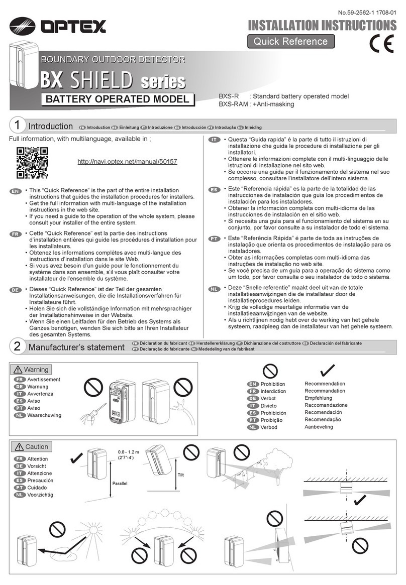
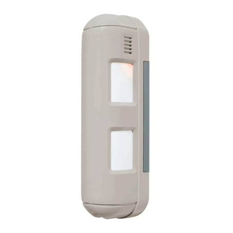
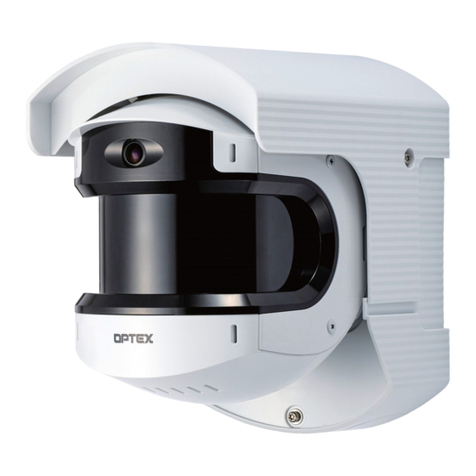
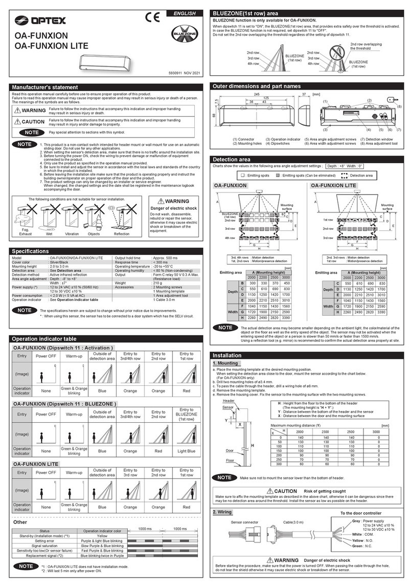
  9. Optex FASTUS CD22-15 Series User manual

Optex FASTUS CD22-15 Series User manual

■NPNtype
Instructionmanual
Precautionsforusinglaser
●RegulationsintheUSA
WhenexportinglaserdevicestotheUSA,theUSAlasercontrol,FDA
(FoodandDrugAdministration)isapplied.Thisproducthasbeenalready
reportedtoCDRH(CenterforDevicesandRadiologicalHealth).For
details,contactourcustomerservice.
Bundledgoodsinthebox
Pleaseconfirmfollowinggoodsbundledinthebox.
・CD22□-□□□□ ・Thisinstructionmanual
●Thelightsourceofthisproductappliesthevisiblelightsemiconductorlaser.Donot
allowthelaserbeamtoenteraneye,eitherdirectlyorreflectedfromreflectiveobject.If
thelaserbeamentersaneye,itmaycauseblindness.
●Thisproductisnotanexplosionproofconstruction.Donotusetheproductunderflam-
mable,explosivegasorliquidenvironment.
●Donotdisassembleormodifytheproductsinceitisnotdesignedtoautomaticallystop
thelaseremissionwhenopen.Disassemblingormodifyingatcustomer'senditmay
causepersonalinjury,fireorelectricshock.
●Useofcontrolsoradjustmentsorperformanceofproceduresotherthanthosespecified
hereinmayresultinhazardousradiationexposure.
●Itisdangeroustowireorattach/removetheconnectorwhilethepowerison.Makesure
toturnoffthepowerbeforeoperation.
●Installinginthefollowingplacesmayresultinmalfunction:
 1.Adustyorsteamyplace
 2.Aplacegeneratingcorrosivegas
 3.Aplacedirectlyreceivingscatteringwateroroil.
 4.Aplacesufferedfromheavyvibrationorimpact.
●Theproductisnotdesignedforoutdooruse.
●Donotusethesensorinatransientstateatpoweron(Approx.15min.Warmupperiod)
●Donotwirewiththehighvoltagecableorthepowerlines.Failuretodothiswillcause
malfunctionbyinductionordamage.
●Donotusetheproductinwater.
●Operatewithintheratedrange.
●Wipeoffdirtontheemitting/receivingpartstomaintaincorrectdetection.Also,avoid
directimpactontheproduct.
WarningMandatoryRequirements
WarningSafetyPrecautions
Indicatesapossiblehazardthatmayresultindeath,serious
injury,WARNINGSorseriouspropertydamageiftheproductis
usedwithoutobservingthestatedinstructions.
CD22Series
CD22-15□□ CD22M-15□□
CD22-35□□ CD22M-15□□
CD22-100□□ CD22M-100□□
-ThankyouforpurchasingCD22series.Wehopeyouaresatisfiedwithitsperformance.
-Pleasereadthismanualcarefullyandkeepitforfuturereference.
Displacementsensor
Dimensions
Connectiondiagram
■PNPtype
■Pinsconfiguration
(sensorside)
■M12type
■M8type
Display
M125pin
Connector
Display
M84pin
Connector
Emitteraxis Emitteraxis
:0V/AnalogGND
:Externalinput
MainCircuit
3.3V
Brown:+V
*:M8connectortype doesn't have
DC12~24V10%
MainCircuit
*:M8connectortypedoes n't hav e
DC12~24V10%Brown:+V
:0V/AnalogGND
::Externalinput
Specifications Setup
Functionsofcomponents
Part
number
Aluminumhousing CD22-15□□ CD22-35□□ CD22-100□□
SUShousing
CD22M-15□□ CD22M-35□□ CD22M-100□□
Centerofmeasurementrange 15mm 35mm 100mm
Measurementrange ±5mm ±15mm ±50mm
Lightsource RedlaserDiode(wavelength 655nm)
Max.output:390μW
Max.output:1mW
※3
Laser
class
IEC/JIS Suffixnul:CLASS1/2:CLASS2(Laser Notice No.50)
Spotsize
※1
500*700μm 450*800μm 600*700μm
Linearity 0.1%ofF.S. 0.1%ofF.S. 0.1%ofF.S.
Repeatability
※2
1μm 6μm 20μm
Samplingperiod 500μs/1000μs/2000μs/ 4000μs / AUTO
Temperaturedrift(typicalvalue)
±0.02%/℃ofF.S. ±0.02%/℃ofF.S.
±0.05%/℃ofF.S.
Indicator Laserindicator:Green/Zeroresetindicator:Red
Outputindicator:Orange/Mode indicator: Red
ExternalInput LaserOFF,Teaching,Sample & Hold, One shot, Zero reset
ControlOutput NPN/PNPmax.100mA/DC30V((Residualvoltage1.8 V max.)
Currentconsumption 70mA max. including Analog output current
Protectioncircuit Reverseconnectionprotection,Over current protection
Protectioncategory IP67 including connection part
OperatingTemp./Humid. -10~50℃/35~85%RHwithout freasing or condensation
StorageTemp./Humid. -20~60℃/ 35 ~85%/RH
Ambientilluminance Incandescentlamp:3,000lxmax.
Vibrationresistence 10~55Hz,Doubleamplitude1.5mm,X,Y,Zfor2 hours
Shockresistence 500mm/s
2
(approx. 50G) X,Y,Z3timeseach
Material
Case:Aluminum/SUS316L,Frontlens:PPSU,Display: PET
Weight AluminumcasewithM12connector: Approx. 60g including
300mmcablewithconnector
SUScasewithM12connector type :Approx. 90g including
300mmcablewithconnector
AluminumcasewithM8connector :Approx. 40g
SUScasewithM8connector :Approx. 70g
Thespecificationsarebasedontheconditionunlessotherwisedesignated:Ambienttemperature:23℃,Sup-
plyvoltage:24VDC,Samplingperiod:500µs,Averaging:64,Measuringdistance:Centeroftherange,Testing
object:Whiteceramic
※1Definedwithcenterstrength1/e
2
(13.5%)atthecenter.Theremaybeleaklightotherthanthespecified
spotsize.Thesensormaybeaffectedwhenthereisahighlyreflectiveobjectclosetothedetectionarea.
※2512averagingtime
※3forLaserClass2type(Model:CD22-100AM122,CD22-100VM122,CD22-100A2,CD22-100V2)
●Specificationspermeasurementrange
●Specificationsperoutput
Partnumber CD22□-□□V CD22□-□□A CD22□-□□-485
Type Voltageoutput Currentoutput RS-485type
Analogoutputrange 0 ~ 10V
※1
4~20mA ー
Maximumloadimpedance ー300Ω ー
Outputimpedance 100Ω ーー
Powersupply DC12-24V±10%
※1
 
※1 Pleasekeeppowersupplyvoltageover12.0VforVoltageoutputtype
 toget0-10Vanalogoutputcorrectly.
●Partnumberlegend
●Controlpanel
●Changingmode
Whileit's"Teachmode","Setupmode"or"Extensionmode",youcanchangethemode
to"Measurementmode"bypressing"ZERO/RUN"button.
Whileit's"Setupmode"or"Extensionmode",theLED"MANUAL"islit.
●Changingparameters
Youcanchooseandadjustthe parameters by pressing "+" and "-" buttons.
Themodewillbechangedto "Measurement mode" by pressing "ZERO/RUN" button .
NEnu
NodE
FGS2
nEAr
FAr
1Pt
FGS2
2Pt
tch
tch
tch
Teachmode
・Screws
M3×15…2
[mm]
・Laserlabel[reserve]
・M12type ・M8type
・LaserWARNINGlabel
・FDACertificationlabel
Laserdiode
Wavelength:655nm,Maxoutput:10mW,//9degreetype.
ExternalInput
Multiplefunctioncanbesetatexternalinput.Whenit'ssetas"Teaching"or"Zeroreset",Thefunction
variesbyinputperiodasfollows.
■Teaching
inputperiod(sec.) Whattoteach(Teachingcurrent position)
0to0.5sec. Donothing
0.5to1.5sec. Currentoutputtype:4mA/Voltageoutputtype:0V
1.5to2.5sec. Currentoutputtype:20mA/Voltageoutputtype10V
2.5to3.5sec. Nearsidethreshold
3.5to4.5sec. Farsidethreshold
over4.5sec. FGS2threshold
■Zeroreset
input(sampling) Function
0to1,999 Zeroreset
over2,000 ReleaseZeroreset
●Specificationsandequipmentaresubjecttochangewithout
anyobligationsonthepartofmanufacture.
●Formoreinformation,questionsandcommentsregarding
products,pleasecontactusbelow.
Attention:NottobeUsedforPersonnelProtection.
Neverusetheseproductsassensingdevicesforpersonnelprotection.Do-
ingsocouldleadtoseriousinjuryordeath.Thesesensorsdonotinclude
theself-checkingredundantcircuitrynecessarytoallowtheiruseinper-
sonnelsafetyapplications.Asensorfailureormalfunctioncancauseeither
anenergizedorde-energizedsensoroutputcondition.
PleaseconsultourdistributorsaboutsafetyproductswhichmeetOSHA,
ANSIandIECstandardsforpersonnelprotection.
91ChudojiAwata-choShimogyo-kuKyoto 600-8815 Japan
TEL:+81-(0)75-325-2920
FAX:+81-(0)75-325-2921
Website:http://www.optex-fa.com
Extensionmode
Extensionmodeischosenbypressing"+"and"-"buttonsatatimefor1second.
ParametersinExtensionmodemustbesetcorrectlyotherwiseitmightnotworkcorrectly.
Pleaseusewithdefaultsettingwhenchangingparametersisnotneeded.("*"meansdefaultsetting)
hYSt
NtoP
thrE
tout
inct
2Ero
SEnS
0.123
NAH
bASE
0.123
Pt5
Pt4
Pt3
Pt2
Pt1
P400
P200
P100
off
100N
SaNp
1
256
Auto
N__6
N__1
Measurementmode
CD22has3measurementmode.Themodeischosenby"Teachmode".
Outputcanbereversedbysetting"Outputpolarity
Acti
".
FollowingoutputshowsitsON/OFFstatusas"LightON
Lon
".
●1pointTeaching
Teachingisdoneataposition.Whenthemeasurementdistanceiscloserthanthatposition,theoutput
willbeON.
●2pointTeaching
Teachingisdoneat2positions.Whilethemeasurementdistanceisbetweenthosepositions,theout-
putwillbeON.
●FGS2
Teachingisdoneataposition.Whenthemeasurementdistanceiscloserthanthedistancesetby"Hys-
teresis
toL
"fromthepositionthatTeachingisdone,theoutputwillbeON.ItworksasFGSsensor.
Setupmode
Setupmodeischosenbypressing"SET"buttonfrom"Menu".(*meansdefaultvalue)
AUG
SANP
1
8
64
500
1000
2000
4000
Auto
NodE
1Pt
FGS2
2Pt
toL
0.123
10U
0U
20nA
4nA
0.123
0.123
0.123
0.123
FGS2
FAr
nEAr
0.123
0.123
0.123
n_P
Acti
inp
nPn
PnP
Lon
Don
oFF
LSr
tch
Sh
onE
2Ero
512
FAr
hYSt
nEAr
hYSt
FGS2
hYSt hYSt
toL
FAr
hYSt
AnalogOutput
AnalogCurrentorAnalogVoltagetypeoutputsAnalogoutputaccordingtothemeasurementdis-
tance.
ThedistancerangeforAnalogoutputissetinTeachingmodeorSetupmode.
10U0U
20nA4nA
approx.24mA
(approx.15V)
Current(Voltage) CD22□-15□□ CD22□-35□□ CD22□-100□□
4nA
(
0U
)-5.000 -15.000 -50.00
20nA
(
10U
) 5.000 15.000 50.00
ALrN
cLNP
hoLD
hdct
0000
hdct
rESt
YES
no
diSP
on
oFF
hoLD
Miscellaneousfunction
●DefaultvalueofeachAnalogoutput type
Loc
uLoc
Loc
0.000
䊻
http://www.optex-fa.com/rohs_cn/
●Thelightsourceofthisproductappliesthevisiblelightsemiconductorlaser.Donot
allowthelaserbeamtoenteraneye,eitherdirectlyorreflectedfromreflectiveobject.If
thelaserbeamentersaneye,itmaycauseblindness.
●Thisproductisnotanexplosionproofconstruction.Donotusetheproductunderflam-
mable,explosivegasorliquidenvironment.
●Donotdisassembleormodifytheproductsinceitisnotdesignedtoautomaticallystop
thelaseremissionwhenopen.Disassemblingormodifyingatcustomer'senditmay
causepersonalinjury,fireorelectricshock.
●Useofcontrolsoradjustmentsorperformanceofproceduresotherthanthosespecified
hereinmayresultinhazardousradiationexposure.
●Itisdangeroustowireorattach/removetheconnectorwhilethepowerison.Makesure
toturnoffthepowerbeforeoperation.
●Installinginthefollowingplacesmayresultinmalfunction:
1.Adustyorsteamyplace
2.Aplacegeneratingcorrosivegas
3.Aplacedirectlyreceivingscatteringwateroroil.
4.Aplacesufferedfromheavyvibrationorimpact.
●Theproductisnotdesignedforoutdooruse.
●Donotusethesensorinatransientstateatpoweron(Approx.15min.Warmupperiod)
●Donotwirewiththehighvoltagecableorthepowerlines.Failuretodothiswillcause
malfunctionbyinductionordamage.
●Donotusetheproductinwater.
●Operatewithintheratedrange.
●Wipe
●
Don'tbendthecablewhenthetemperatureofthecableoratmosphereisbelowfreezing.
offdirtontheemitting/receivingpartstomaintaincorrectdetection.Also,avoid
directimpactontheproduct.
WarningMandatoryRequirements
WarningSafetyPrecautions
Indicatesapossiblehazardthatmayresultindeath,serious
injury,WARNINGSorseriouspropertydamageiftheproductis
usedwithoutobservingthestatedinstructions.
CD22 Series
CD22-15□□ CD22M-15□□
CD22-35□□ CD22M-15□□
CD22-100□□ CD22M-100□□
-ThankyouforpurchasingCD22series.Wehopeyouaresatisfiedwithitsperformance.
-Pleasereadthismanualcarefullyandkeepitforfuturereference.
Displacement sensor
Dimensions
Connectiondiagram
■PNPtype
■Pinsconfiguration
(sensorside)
■M12type
■M8type
Display
M12 5pin
Connector
Display
M8 4pin
Connector
Emitter axis Emitter axis
: 0V / Analog GND
: Exter nal i nput
Main Circuit
3.3V
Brown : +V
* : M 8 connector type doesn' t have
DC 12~24V 10%
Main Circuit
* : M 8 connector type doesn' t have
DC 12~24V 10%Brown : +V
: 0V / Analog GND
: : Exter nal input
・Screws
M3 × 15…2
[mm]
・Laserlabel[reserve]
・M12type ・M8type
・LaserWARNINGlabel
・FDACertificationlabel
Laserdiode
Wavelength:655nm,Maxoutput:10mW,//9degreetype.
Ramco Innovations
(
800
)
280-6933 www.optex-ramco.com nsales
@
ramcoi.com
For technical and application support contact Ramco - today!
Setup
Part
number
Aluminum housing &'ƑƑ &'ƑƑ &'ƑƑ
SUS housing
&'0ƑƑ &'0ƑƑ &'0ƑƑ
Center of measurement range 15mm 35mm PP
Measurement range ±5mm ±15mm PP
Light source Red laser Diode (wave length 655nm)
0D[RXWSXW:
Max. output: 1mW ※3
Laser
class
IEC/JIS
Spot size ※1P P P
Linearity RIF.S. RIF. S. RIF. S.
Repeatability ※2P P P
Sampling period VVVV AUTO
Temperature drift (typical value)
℃of F.S. ℃of F.S.
℃of F.S.
Indicator Laser indicator: Green / Zero reset indicator: Red
Output indicator: Orange / Mode indicator: Red
Communication I/F 56+DOI'XSOH[0XOWLGURS,)LVQRWVXSSRUWHG
Power supply 9'&
Current consumption PA max.
Protection circuit Reverse connection protection, Over current protection
Protection category ,3LQFOXGLQJFRQQHFWLRQSDUW
Operating THPS+XPLG ~℃a5+ZLWKRXWIUHDVLQJRUFRQGHQVDWLRQ
Storage THPS+XPLG a℃/ 35 ~5+
Ambient illuminance ,QFDQGHVFHQWODPSO[PD[
9ibration resistance a+]'RXEOHDPSOLWXGHPP;Y,Z for 2 hours
Shock resistance PPV2DSSUR[*;Y,Z 3 times each
Material
Case: Aluminum/SUS316L, Front lens: PPSU, Display: PET
Weight Aluminum case with M12 connector : $SSUR[JLQFOXGLQJ
PPFDEOHZLWKFRQQHFWRU
SUS case with M12 connector type : $SSUR[JLQFOXGLQJ
PPFDEOHZLWKFRQQHFWRU
$OXPLQXPFDVHZLWK0FRQQHFWRU $SSUR[J
686FDVHZLWK0FRQQHFWRU $SSUR[J
℃, Sup
ply voltage: 9'& Sampling period: V Averaging: 64, Measuring distance: Center of the range, Testing
object: White ceramic
※2
※2 512 averaging time
※/DVHU&ODVVW\SH0RGHO&'0&'&
●
●Part number legend
㻯㻌㻰㻌㻞㻌㻞㻌
䠻㻙㻌䠻㻌䠻㻌䠻㻌䠻㻌䠻㻌䠻㻌䠻㻌䠻㻌䠻
Measurement center distance (mm)
Output
Laser Class
Connector ƔM12 : M12
ƔC : Mconnector
Ɣ9: 9oltage 9
ƔA : Current 4mA
Ɣ : RS5
ƔNul : Class 1
Ɣ2 : Class 2
&DVH ƔNul : Aluminum
ƔM : SUS316L
●Changingmode
Whileit's"Teachmode","Setupmode"or"Extensionmode",youcanchangethemode
to"Measurementmode"bypressing"ZERO/RUN"button.
Whileit's"Setupmode"or"Extensionmode",theLED"MANUAL"islit.
●Changing parameters
YRXFDQFKRRVHDQGDGMXVWWKHSDUDPHWHUVE\SUHVVLQJDQGEXWWRQV
The mode will be changed to "Measurement mode" by pressing "ZERO/RUN" button.
㻿㻱㼀
䠉䠇䠉 䠇
㻯㼔㼍㼚㼓㼕㼚㼓
㼜㼍㼞㼍㼙㼑㼠㼑㼞
㻭㼐㼖㼡㼟㼠㼕㼚㼓
㼜㼍㼞㼍㼙㼑㼠㼑㼞
㻹㼑㼍㼟㼡㼞㼑㼙㼑㼚㼠
㻌㻌㻌㻌㻌㻌㻌㻌㻌㻌㻌㻌㼙㼛㼐㼑
㼀㼑㼍㼏㼔㼕㼚㼓㻌㼙㼛㼐㼑
㻿㼑㼠㼡㼜㻌㼙㼛㼐㼑
㻱㼤㼠㼑㼚㼟㼕㼛㼚㻌㼙㼛㼐㼑
㻼㼞㼑㼟㼟㻌㼍㼠㻌㼍㻌㼠㼕㼙㼑
㼒㼛㼞㻌㻞㻌㼟㼑㼏㼛㼚㼐
Teach mode
mEnu
modE
FG52
nEAr
FAr
1pt
fG52
2pt
㻿㻱㼀
㻿㻱㼀
1 point Teaching
FGS2
2 point Teaching
tch
㻿㻱㼀
tch
㻿㻱㼀
tch
7HDFKLQJFXUUHQWSRVLWLRQ
㻿㻱㼀
To Setup mode
ٹ
Setup mode
ٹ
Teaching mode
ٹ
FGS2 threshold
CALn
㻿㻱㼀
tch
7HDFKLQJFXUUHQWSRVLWLRQ
ٹ
Calibration(Near end of range)
calf
㻿㻱㼀
tch
7HDFKLQJFXUUHQWSRVLWLRQ
ٹ
Calibration(Far end of the range)
ٹ
1HDUVLGHWKUHVKROG
ٹ
SRLQW7HDFKLQJ)DUVLGHWKUHVKROG
䠇
䞊
䠇
䞊
䠇
䞊
䠇
䞊
䠇
䞊
䠇
䞊
䠇
䞊
䠇䞊
VZLWFKLQJ
Measurement mode
CD22 has 3 measurement mode. The mode is chosen by "Teach mode".
Output can be reversed by setting "Output polarity Acti
Following output shows its ON/OFF status as "Light ON

L on
●1 point Teaching
Teaching is done at a position. When the measurement distance is closer than that position, the output
●2 point Teaching
●Calibration (Far end of the range/ Near end of range)
Teaching is done at 2 positions. While the measurement distance is between those positions, the output
The sensor can be calibrated by “Calibration” mode at both far and near end of the measurement range.
This feature is very useful especially when you can’t mount the sensor head parallel to the object surface.
●FGS2
Teaching is done at a position. When the measurement distance is closer than the distance set by +\V
toL
teresis
FAr
hYSt
㻻㻺
㻻㻲㻲
nEAr
hYSt
FGS2
hYSt
㻹㼑㼍㼟㼡㼞㼑㼙㼑㼚㼠㻌㼞㼍㼚㼓㼑
㻻㻺
㻻㻲㻲
hYSt
toL
FAr
hYSt
㻹㼑㼍㼟㼡㼞㼑㼙㼑㼚㼠㻌㼞㼍㼚㼓㼑
㻻㻺
㻻㻲㻲
Position of the target
PP䠄Near end of the range䠅
PP䠄Far end of 㼠㼔㼑㻌㼞㼍㼚㼓㼑䠅
PP䠄Reference distance䠅
㼙㼑㼍㼟㼡㼞㼑㼙㼑㼚㼠㻌㼞㼑㼟㼡㼘㼠䠖
㻙㻡㻜㻚㻜㻜
㼙㼑㼍㼟㼡㼞㼑㼙㼑㼚㼠㻌㼞㼑㼟㼡㼘㼠䠖
㻡㻜㻚㻜㻜
㼙㼑㼍㼟㼡㼞㼑㼙㼑㼚㼠㻌㼞㼑㼟㼡㼘㼠䠖
㻙㻠㻥㻚㻤㻝
㼙㼑㼍㼟㼡㼞㼑㼙㼑㼚㼠㻌㼞㼑㼟㼡㼘㼠䠖
㻡㻜㻚㻝㻥
cALn
㻿㻱㼀
㻙㻡㻜㻚㻜㻜
cALF
㻿㻱㼀
㻡㻜㻚㻜㻜
([DPSOHRI&DOLEUDWLRQRI&'
●
Just calibrate the sensor by “Calibration” mode at far end and near end of the measurement range.
Then, you will get calibrated result if the sensor head is tilted.
A䠅Calibration condition at the factory B䠅When the sensor is mounted tilted
".
".
will be ON.
will be ON.
"from the position that Teaching is done, the output will be ON. It works as FGS sensor.
Ramco Innovations
(
800
)
280-6933 www.optex-ramco.com nsales
@
ramcoi.com
ExternalInput
Multiplefunctioncanbesetatexternalinput.Whenit'ssetas"Teaching"or"Zeroreset",Thefunction
variesbyinputperiodasfollows.
■ Teaching
input period (sec.) What to teach (Teaching current position)
0 to 0.5 sec. Donothing
0.5 to 1.5 sec. Currentoutputtype:4mA/ Voltage output type:0V
1.5 to 2.5 sec. Currentoutputtype:20mA/ Voltage output type 10V
2.5 to 3.5 sec. Near side threshold
3.5 to 4.5 sec. Far side threshold
over 4.5 sec. FGS2 threshold
■ Zero reset
input ( sampling ) Function
0 to 1,999 Zero reset
over 2,000 Release Zero reset
Measurementmode
CD22has3measurementmode.Themodeischosenby"Teachmode".
Outputcanbereversedbysetting"Outputpolarity Acti ".
FollowingoutputshowsitsON/OFFstatusas"LightON L on ".
●1pointTeaching
Teachingisdoneataposition.Whenthemeasurementdistanceiscloserthanthatposition,theoutput
willbeON.
●2pointTeaching
Teachingisdoneat2positions.Whilethemeasurementdistanceisbetweenthosepositions,theout-
putwillbeON.
●FGS2
Teachingisdoneataposition.Whenthemeasurementdistanceiscloserthanthedistancesetby"Hys-
teresis toL "fromthepositionthatTeachingisdone,theoutputwillbeON.ItworksasFGSsensor.
Setupmode
Setupmodeischosenbypressing"SET"buttonfrom"Menu".(*meansdefaultvalue)
AUG
SANP
1
8
64
500
1000
2000
4000
Auto
NodE
1Pt
FGS2
2Pt
toL
0.123
10U
0U
20nA
4nA
0.123
0.123
0.123
0.123
FGS2
FAr
nEAr
0.123
0.123
0.123
n_P
Acti
inp
nPn
PnP
L on
D on
oFF
LSr
tch
S h
onE
2Ero
512
FAr
hYSt
nEAr
hYSt
FGS2
hYSt hYSt
toL
FAr
hYSt
AnalogOutput
AnalogCurrentorAnalogVoltagetypeoutputsAnalogoutputaccordingtothemeasurementdis-
tance.
ThedistancerangeforAnalogoutputissetinTeachingmodeorSetupmode.
10U0U
20nA4nA
approx. 24mA
(approx. 15V)
Current ( Voltage) CD22□-15□□ CD22□-35□□ CD22□-100□□
4nA (0U )- 5.000 - 15.000 - 50.00
20nA ( 10U ) 5.000 15.000 50.00
●Default value of each Analog output type
Ramco Innovations (800) 280-6933 www.optex-ramco.com [email protected]
● Specificationsandequipmentaresubjecttochangewithout
anyobligationsonthepartofmanufacture.
● Formoreinformation,questionsandcommentsregarding
products,pleasecontactusbelow.
Attention:NottobeUsedforPersonnelProtection.
Neverusetheseproductsassensingdevicesforpersonnelprotection.Do-
ingsocouldleadtoseriousinjuryordeath.Thesesensorsdonotinclude
theself-checkingredundantcircuitrynecessarytoallowtheiruseinper-
sonnelsafetyapplications.Asensorfailureormalfunctioncancauseeither
anenergizedorde-energizedsensoroutputcondition.
PleaseconsultourdistributorsaboutsafetyproductswhichmeetOSHA,
ANSIandIECstandardsforpersonnelprotection.
91 Chudoji Awata-cho Shimogyo-ku Kyoto 600-8815 Japan
TEL: +81-(0)75-325-1314
FAX: +81-(0)75-325-2936
Extensionmode
Extensionmodeischosenbypressing"+"and"-"buttonsatatimefor1second.
ParametersinExtensionmodemustbesetcorrectlyotherwiseitmightnotworkcorrectly.
Pleaseusewithdefaultsettingwhenchangingparametersisnotneeded.("*"meansdefaultsetting)
hYSt
NtoP
thrE
tout
inct
2Ero
SEnS
0.123
NAH
bASE
0.123
Pt5
Pt4
Pt3
Pt2
Pt1
P400
P200
P100
off
100N
SaNp
1
256
Auto
N__6
N__1
ALrN
cLNP
hoLD
hdct
0000
hdct
rESt
YES
no
diSP
on
oFF
hoLD
Miscellaneousfunction
Loc
uLoc
Loc
0.000
䊻http://www.optex-fa.com/rohs_cn/
Website : http://www.optex-fa.com
Ramco Innovations
(
800
)
280-6933 www.optex-ramco.com nsales
@
ramcoi.com

This manual suits for next models

5

Other Optex Security Sensor manuals

Optex RLS-50100V User manual

Optex

Optex RLS-50100V User manual

Optex AX-330PLUS User manual

Optex

Optex AX-330PLUS User manual

Optex WX Shield Series User manual

Optex

Optex WX Shield Series User manual

Optex BX SHIELD Series User manual

Optex

Optex BX SHIELD Series User manual

Optex AP-360B User manual

Optex

Optex AP-360B User manual

Optex RXC-DT-X5 User manual

Optex

Optex RXC-DT-X5 User manual

Optex OVS-01CC User manual

Optex

Optex OVS-01CC User manual

Optex Fiber SenSys Laser Defender LD308SH Installation and operating instructions

Optex

Optex Fiber SenSys Laser Defender LD308SH Installation and operating instructions

Optex ELITE T User manual

Optex

Optex ELITE T User manual

Optex HX-40RAM User manual

Optex

Optex HX-40RAM User manual

Optex Redwall LRP 180QH Assembly instructions

Optex

Optex Redwall LRP 180QH Assembly instructions

Optex OA-AXIS I User manual

Optex

Optex OA-AXIS I User manual

Optex AP-360BR User manual

Optex

Optex AP-360BR User manual

Optex VX-402R User manual

Optex

Optex VX-402R User manual

Optex HX-40 User manual

Optex

Optex HX-40 User manual

Optex CX-502 User manual

Optex

Optex CX-502 User manual

Optex VX SHIELD Series User manual

Optex

Optex VX SHIELD Series User manual

Optex FlipX Series User manual

Optex

Optex FlipX Series User manual

Optex HX-80N User manual

Optex

Optex HX-80N User manual

Optex inSight INS-HX-80N User manual

Optex

Optex inSight INS-HX-80N User manual

Optex BX SHIELD User manual

Optex

Optex BX SHIELD User manual

Optex AX-100TFR Series User manual

Optex

Optex AX-100TFR Series User manual

Optex SX-360Z User manual

Optex

Optex SX-360Z User manual

Optex WFX-360HW User manual

Optex

Optex WFX-360HW User manual

Popular Security Sensor manuals by other brands

SDC MD-31D installation instructions

SDC

SDC MD-31D installation instructions

Aritech VE1120 Series Installation sheet

Aritech

Aritech VE1120 Series Installation sheet

C-LOGIC 610-MD instruction manual

C-LOGIC

C-LOGIC 610-MD instruction manual

Sminn COMPATTA CONTROL Assembly instructions

Sminn

Sminn COMPATTA CONTROL Assembly instructions

Greenlee 2010 instruction manual

Greenlee

Greenlee 2010 instruction manual

Honeywell Eclipse Installing

Honeywell

Honeywell Eclipse Installing

Taco LeakBreaker LBW Series instruction sheet

Taco

Taco LeakBreaker LBW Series instruction sheet

ADEMCO ASC25 Series installation instructions

ADEMCO

ADEMCO ASC25 Series installation instructions

DBI SALA SAFLOCK 2100103 Specific instructions

DBI SALA

DBI SALA SAFLOCK 2100103 Specific instructions

Siemens SITRANS F FUH1010 Series operating instructions

Siemens

Siemens SITRANS F FUH1010 Series operating instructions

Atim Cloud Wireless LoRaWAN ACW/LW8-THX user guide

Atim Cloud Wireless

Atim Cloud Wireless LoRaWAN ACW/LW8-THX user guide

STEINEL IR 180 Information

STEINEL

STEINEL IR 180 Information

Neilsen CT2129 instruction manual

Neilsen

Neilsen CT2129 instruction manual

Elkron IR200 quick start guide

Elkron

Elkron IR200 quick start guide

Honeywell LightSpot LS1000R Installation and operating instructions

Honeywell

Honeywell LightSpot LS1000R Installation and operating instructions

Scott Safety MultiFlame FV-40 Series user guide

Scott Safety

Scott Safety MultiFlame FV-40 Series user guide

Maximum OUT LOOK quick reference

Maximum

Maximum OUT LOOK quick reference

ST X-NUCLEO-IKS02A1 user manual

ST

ST X-NUCLEO-IKS02A1 user manual

manuals.online logo
manuals.online logoBrands
  • About & Mission
  • Contact us
  • Privacy Policy
  • Terms and Conditions

Copyright 2025 Manuals.Online. All Rights Reserved.