Page 10
4.4 Always keep the iris diaphragm completely open when working with uorescence light.
4.5 Brightelduse:Lampsettings
The microscope is tted with a 3.5W X-LED3 illuminator. Insert the plug of the cable into the power
socket and turn on the switch on the back of the main body. Turn the brightness adjustment knob to a
brightness suitable for observation.
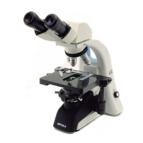
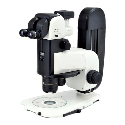
4.6 Adjust interpupillary distance
Hold the right and left parts of the observation head by both hands and adjust the interpupillary
distance by turning the two parts until one circle of light can be seen. After nishing the interpupillary
adjustment, turn the dioptric adjustment ring on the left eye tube to the “0” position at the graduation
line on the eyetube.
4.7 Focus and diopter adjustment
Loosen the focus-stop knob, rotate the coarse focusing knob to bring the slide into focus with an
objective with a low magnication, and then lock the focus-stop knob. Adjust the ne focusing knob to
get the image sharp and clear while observing with your right eye, then turn the left dioptric adjustment
ring to a sharp and clear image also with the other eye. Turn the tension-adjust-knob to get a suitable
tension for the focus system. When the image is in focus, turn the nosepiece to choose the objective
you need.
4.8 Brightelduse:Condenseradjustment
Turn the condenser adjustment knob to move the condenser up or down for a clear and uniform
sample illumination. The two condenser-centring screws can be used to centre the condenser.
4.9 Brightelduse:Setthenumericalaperture
Adjust the aperture of the iris diaphragm located under the condenser, to set the numerical aperture
of the illuminator, thus controlling image contrast and resolution.
4.10 Brightelduse:Fielddiaphragm
Adjust the eld diaphragm to align the system and to control stray light.
4.11 Brightelduse:Additionallters
The chromatic correction lter (blue) and the monochromator lter (green) can be inserted into the
lter holder for denition of specimen parts. The use of the green lter is recommended for phase
contrast observations.
4.12 Brightelduse:Usingthepolarizer(optional)
The polarizing set consists of two lters; the analyser and the polarizer. The analyser is placed in the
analyser holder (you have to remove the orange protection lter in order to access the holder) and
the polarizer on top of the illuminator.
4.13 Videocapturing(optional)
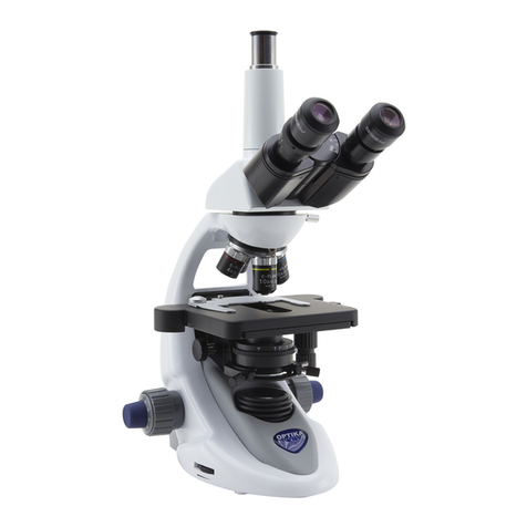
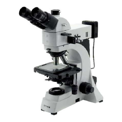
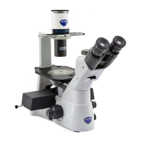
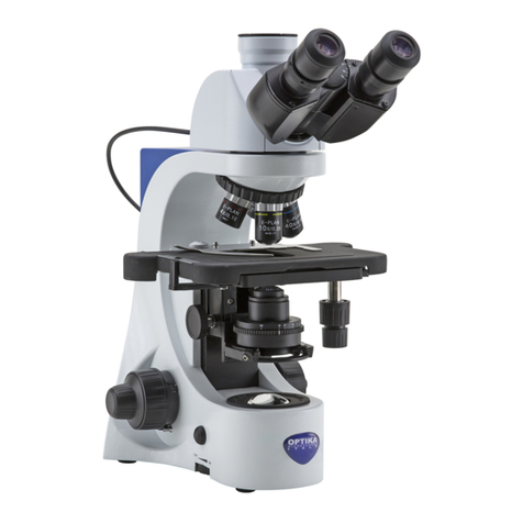
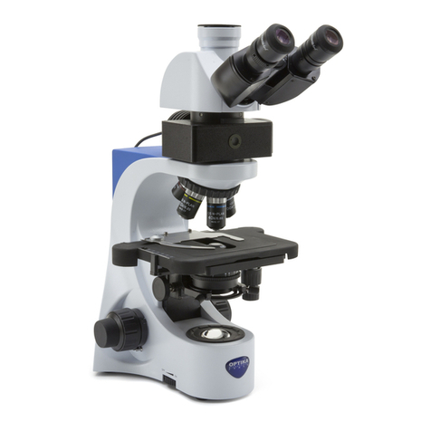
B-500TiFL is provided with trinocular observation head. It can be connected to cameras via a photo/
video adaptor, for photo and video capturing. Before taking a picture or lming video, if necessary,
obscure with a dark cloth both the camera viewnder and the eyepieces and pull out the light path
selector lever. Please refer to the adaptor and camera manuals for further details.
4.0 USING THE MICROSCOPE
