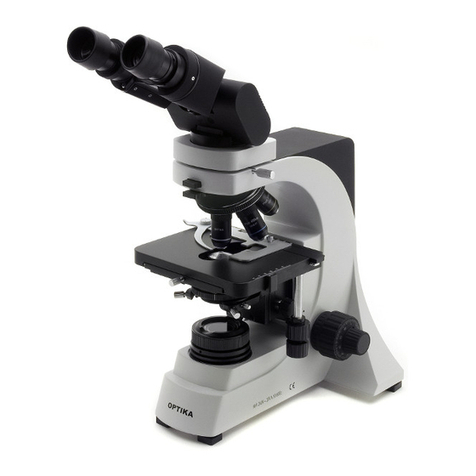
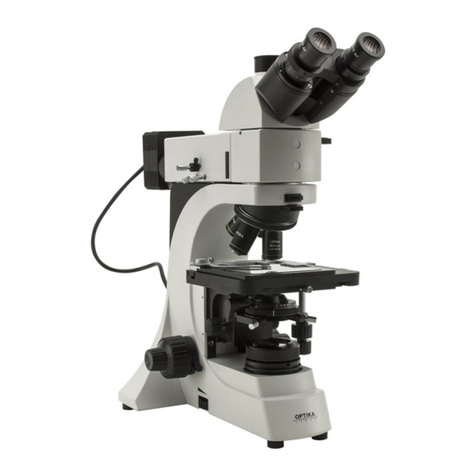
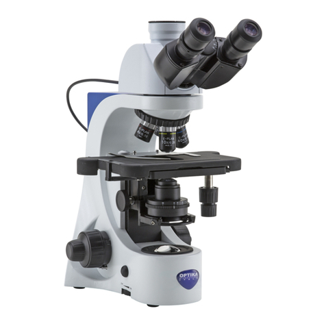
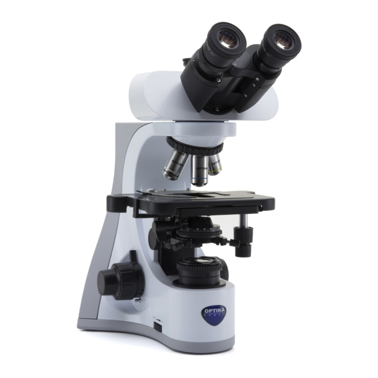
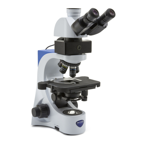
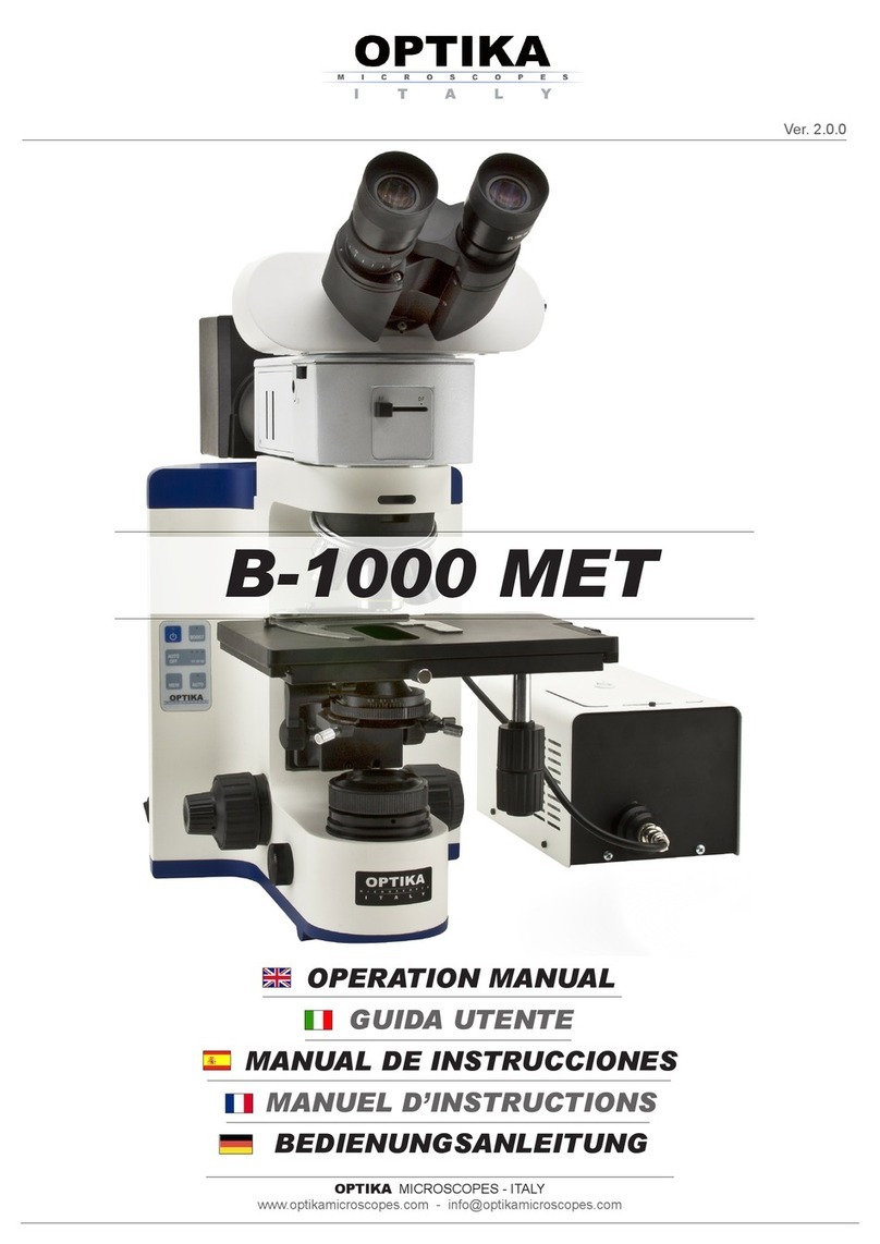
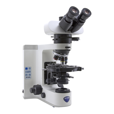
Optika B-500POL User manual

B-500POL
OPERATION MANUAL

Page 2
INDEX
1.0 DESCRIPTION page 4
2.0 INTRODUCTION page 6
3.0 UNPACKING AND ASSEMBLY page 6
4.0 USING THE MICROSCOPE page 8
5.0 MAINTENANCE page 12
6.0 TECHNICAL SPECIFICATIONS page 13
7.0 RECOVERY AND RECYCLING page 14

Page 3
This microscope is a scientic precision instrument designed to last for many years with a minimum of main-
tenance. It is built to high optical and mechanical standards and to withstand daily use.
Optika reminds you that this manual contains important information on safety and maintenance, and that it
must therefore be made accessible to the instrument users.
Optika declines any responsibility deriving from instrument uses that do not comply with this ma-nual.
Safety guidelines
This manual contains important information and warnings regarding safety about installation, use and
maintenance of the microscope. Please read this manual carefully before using the equipment. To
ensure safe use, the user must read and follow all instructions in this manual. OPTIKA products are
designed for safe use in normal operating conditions. The equipment and accessories described in
the manual are manufactured and tested according to industry standards for safety instrumentation
laboratory. Misuse can cause personal injury or damage to the instrument. Keep this manual at hand
close to the instrument, for an easy consultation.
Electrical safety
Before connecting the power cord to wall outlet, ensure that your mains voltage for your region corre-
sponds to the voltage supply of the instrument, and that the illuminator’s switch is in position OFF. The
user must observe the safety regulations in force in his region. The instrument is equipped with CE sa-
fety marking, in any case the user has full responsibility concerning the safe use of that instrument.
Warning/Caution symbols used in this manual
The user should be aware of safety aspects when using the instrument. Warning or hazard symbols
are shown below. These symbols are used in this manual.
The instructions on this symbol to avoid possible severe personal injuries.
Warning of use; the incorrect operation on the instrument can cause damages
to the person or instrument.
Possibility of electric shock.
Attention: high temperature surfaces. Avoid direct contact.
Technical notes or usage tips.
SAFETY GUIDELINES
Page 4
1.0 DESCRIPTION
PHOTO PORT
LEVER
EYEPIECE
FILTER
PLATE HOLDER
FIELD DIAPHRAGM
STAGE LOCK
KNOB
FILTERS
OBSERVATION
HEAD
NOSEPIECE
STAGE
APERTURE DIAPHRAGM
OBJECTIVE
TENSION
ADJUSTMENT
KNOB
COARSE FOCUSING
KNOB
FINE FOCUSING KNOB
POLARIZER

Page 5
1.0 DESCRIPTION
ANALYZER
INSERTION LEVER
DIOPTRIC ADJUSTMENT RING
BERTRAND LENS
DISC
CONDENSER
CENTERING
KNOBS
BRIGHTNESS ADJUSTMENT
KNOB
CONDENSER ADJUSTMENT
KNOB
FOCUS-STOP KNOB

Page 6
This microscope is a scientic precision instrument designed to last for many years with a minimum of main-
tenance. It is built to high optical and mechanical standards and to withstand daily laboratory use.
Optika reminds you that this manual contains important information on safety and maintenance, and that it
must therefore be made accessible to the instrument users.
Optika declines any responsibility deriving from instrument use that does not comply with this manual.
3.0 UNPACKING AND ASSEMBLY
2.0 INTRODUCTION
3.1 The microscope is housed in a moulded Styrofoam container. Remove the tape from the edge of the
container and lift the top half of the container. Take some care to avoid that the optical items (objecti-
ves and eyepieces) fall out and get damaged. Using both hands (one around the arm and one around
the base), lift the microscope from the container and put it on a stable desk.
3.2 The objectives are located in individual protective vials. Remove the objectives from the vials and
insert them into the microscope nosepiece in the order from the lowest magnication to the highest, in
a clockwise direction from the rear.
3.3 Insert the analyzer/bertrand lens block onto the top of the microscope stand and lock its screw:

Page 7
3.4 Insert the observation head onto the top of the analyzer/bertrand lens block and lock its screw. If you
have a trinocular microscope and want to use the photo port, insert your adaptor in the hole on the
top of the observation head and xate it with the screw on the side:
3.5 Insert the eyepieces into the eye tubes.
3.6 Insert the condenser into its holder and lock its screw:
3.0 UNPACKING AND ASSEMBLY

Page 8
4.1 Adjust the observation head
Loosen the lock-screw, turn the observation head to a comfortable position for observation, and then
lock the lock-screw.
4.2 Place the specimen on the stage
Fix the specimen slide on the mechanical stage using the slide-clamp. Ensure that the specimen is
centred over the stage opening.
4.3 Lamp settings
In order to activate the transmitted light illuminator, insert the plug of the mains cable into the mains
socket and turn on the switch on the back of the main body. Turn the brightness adjustment knob to
a brightness suitable for observation.
4.4 Preliminary settings
Before trying to focus the sample, ensure that:
The eld diaphragm is fully open.
The aperture diaphragm is fully open.
No lter is inserted under the observation head.
The analyzer lter is in OUT position (lever fully pulled out).
Photo port closed (lever fully in).
Bertrand lens in OUT position (you read “0” on the Bertrand lens disc under the observation
head). Swing out lens of the condeser in OUT position (you have always to do this when observing
through 4X and 10X objective).
3.0 UNPACKING AND ASSEMBLY
4.0 USING THE MICROSCOPE
Connect the mains plug into the socket at the base
Make sure, before you turn the illumination on, that the voltage selector is set to the mains voltage for
your region.
The power cord should be used only on network sockets equipped with adequate grounding.
Contact a technician to check the state of your electrical system. If there is no need to install additional
accessories, the instrument is now ready for use. Once positioned and installed with the necessary
components, the microscope is ready to be used. Your microscope is a laboratory instrument desi-
gned to last. Handle it always carefully and avoid abrupt vibrations or shocks. Always disconnect the
power cable from the microscope when not in use for long time, while you clean it or when you perform
any maintenance.
AVOID DISASSEMBLING THE INSTRUMENT
Do not disassemble the instrument. This entails the cancellation of the warranty and may cause
malfunction.

Page 9
4.5 Adjust interpupillary distance
Hold the right and left parts of the observation head using both hands and adjust the interpupillary
distance by turning the two parts until one circle of light can be seen.
4.6 Focus and diopter adjustment
Loosen the focus-stop knob, rotate the coarse focusing knob to bring the slide into focus with a 4X
or 10X objective, then lock the focus-stop knob. Adjust the ne focusing knob to get the image sharp
and clear while observing with your right eye, then turn the left diopter ring to a sharp and clear
image also with the other eye. Turn the tension-adjust-knob to get a suitable tension for the focus
system.
4.7 Align the system
Insert the swing out lens of the condenser and fully close the eld diaphragm. Rotate the condenser
adjustment knob until you see a sharp image of the closed eld diaphragm (a bright spot of light).
Act on the condenser centering screws until you move the bright spot in the center of the image
eld. Then re-open the eld diaphragm.
4.8 Center the stage
With the Bertrand lens out, focus on your slide. Center the optical axis of the objective you are using
with the rotation axis of the stage using the two centring screws above each objective.
A fairly easy method of centring is the following: look at your sample while continuously rotating the
stage clockwise and then counter-clockwise by a little angle (e.g. 30° or 45°). During these oscilla-
tions you should spot a point on the sample that doesn’t rotate on a circumference but only revol-
ving about itself. With the two objective’s centering screws, bring this point in the center of the eld
of view. In this way the mechanical center of rotation of the stage coincides with the system’s optical
axis. The stage can be locked in its position using the stage lock knob.
4.0 USING THE MICROSCOPE
INSERT HERE
THE PROVIDED
SCREWDRIVERS TO
CENTER THE OBJECTIVE

Page 10
4.9 Set the numerical aperture
Adjust the aperture of the iris diaphragm under the condenser to set the numerical aperture of the
illuminator, thus controlling image contrast and resolution.
4.10 Bertrand lens
In order to have a conoscopic view of your sample, you can insert a Bertrand lens in the optical path
by rotating the disc under the observation head.
The Bertrand lens can be ne aligned along Z axis by rotating this disc:
The lens can also be centered in X-Y axis by means of two screws located at the back of the lens:
4.0 USING THE MICROSCOPE
“B”: BERTRAND LENS IN
“0”: BERTRAND LENS OUT
BERTRAND LENS Z- AXIS
CENTERING DISC

Page 11
4.11 Polarizerandanalyzerlters
Insert or remove the lower polarizer as required. It can also be rotated at any angle:
The analyzer lter can be inserted by means of its lever under the observation head. By holding this lever, it
can laso be rotated at any angle:
4.0 USING THE MICROSCOPE

Page 12
4.12 Retardationlterplates
The microscope is provided with these retardation plates: l, l/4 and quartz wedge. You can insert
them in the optical path, sliding the plate holder in the slot under the observation head:
5.1 Always think about
- The following environment is required: Indoor temperature: 0-40°C, Maximum relative humidity: 85
% (non condensing)
- Keep the microscope away from dust and shocks while in use.
- Turn off the light immediately after use.
- Use a soft lens tissue to clean the optics after use.
- Only if needed, use a cloth moistened with water and a mild detergent, rinsing with water and drying
immediately with a lint-free cloth.
- After use, cover the microscope with the included dust-cover, and keep it in a dry and clean place.
5.2 Do not!
- Wipe the surface of any optical items with your hands. Fingerprints can damage the optics.
- Use solvents, neither on the microscope, nor on the optics.
- Disassemble objective or eyepieces to attempt to clean them.
- Mishandle or impose unnecessary force on the microscope.
- Clean the unit with volatile solvents or abrasive cleaners.
- Attempt to service the microscope yourself.
4.0 USING THE MICROSCOPE
5.0 MAINTENANCE

Page 13
6.0 TECHNICAL SPECIFICATIONS
ILLUMINATION Light source type X-LED with white LED; light intensity control using a knob on left side of
the frame.
LED power 3.6W, comparable to an halogen bulb 35W.
Color temperature: 6300K
LED average lifetime approx.: 50.000h.
The light exit can be used as a lter holder for additional lters (blue, yellow, frosted).
Voltage: 110/230Vac, 50/60Hz, 0.4/0.8A; Fuse: T3.15A 250V
Max power required: 7W
OBSERVATION
MODES
Brighteld, Polarized transmitted light
FOCUSING Coaxial coarse and ne focusing mechanism (graduated, 0.002mm) with upper stop, to
prevent the contact between objective and specimen. Adjustable tension of coarse focusing
knob.
STAGE Rotatable stage with locking system and Vernier scale with accuracy 0,1 mm.
Diameter 160 mm. Specimen clamps.
NOSEPIECE Quadruple revolving nosepiece, rotation on ball bearings.
Centering system on each objective.
HEAD Trinocular observation head, inclined 30° and rotatable 360°.
Diopter adjustment on left eyepiece sleeve. Interpupillary adjustment 55-75 mm.
EYEPIECES Wide eld eyepieces WF10X/22 with eld number 22.
One eyepiece has a built-in crosshair reticle for the centering of the optical path.
OBJECTIVES Innity corrected optical system IOS (Innity Optical System).
Plan-achromatic “strain-free” objectives innity corrected, made by following objectives:
-) PLAN IOS POL 4X , A.N. 0.10, W.D. 4,7 mm
-) PLAN IOS POL 10X, A.N. 0.25, W.D. 4,1 mm
-) PLAN IOS POL 40X, A.N. 0.65, W.D. 0,5 mm
-) PLAN IOS POL 60X, A.N. 0.85, W.D. 0,1 mm
All objectives are treated with an anti-fungus treatment.
CONDENSER Abbe condenser, N.A. 0,9 with centering system.
Rotatable polarizer with graduated scale (it can be excluded from optical path through rota-
tion).
BERTRAND LENS Swing-out type with centering and focusing mechanism for observation in conoscopy/or-
thoscopy.
Rotatable analyzer from 0° to 90° with graduated scale.
Tint plates included:
-) 1° order red (1 lambda) -) ¼ lamdba -) Quartz wedge
DIMENSIONS HEIGHT: 480 mm WIDHT: 245 mm
DEPTH: 380 mm WEIGHT: 9 kg
ACCESSORIES Instruction manual and dust cover included.

Page 14
Art.13 Dlsg 25 july 2005 N°151. “According to directives 2002/95/EC, 2002/96/EC and 2003/108/EC relating
to the reduction in the use of hazardous substances in electrical and electronic equipment and waste dispo-
sal.”
The basket symbol on equipment or on its box indicates that the product at the end of its useful life should be
collected separately from other waste.
The separate collection of this equipment at the end of its lifetime is organized and managed by
the producer. The user will have to contact the manufacturer and follow the rules that he adop-
ted for end-of-life equipment collection. The collection of the equipment for recycling, treatment
and environmentally compatible disposal, helps to prevent possible adverse effects on the environ-
ment and health and promotes reuse and/or recycling of materials of the equipment. Improper dispo-
sal of the product involves the application of administrative penalties as provided by the laws in force.
7.0 RECOVERY AND RECYCLING


www.optikamicroscopes.com
info@optikamicroscopes.com
OPTIKA
S.R.L.
Via Rigla 30, Ponteranica (BG) -
ITALY
Tel.: ++39 035 571392 (6 linee) Telefax: ++ 39 035
571435
MAD Iberica Aparatos
Cientificos
c/. Puig i Pidemunt, nº 28 1º 2ª - (Pol. Ind. Plà d’en Boet) 08302 MATARO
(Barcelona) España Tel: +34 937.586.245 +34 937.414.529
New York Microscope Company Inc
100 Lauman Lane, Suite A, Hicksville, New York 11801, USA
Tel.: 877.877.7274 - Fax: 516.801.2046
www.microscopeinternational.com -
info@nyscopes.com
OPTIKA MICROSCOPES -
ITALY
www.optikamicroscopes.com -
info@optikamicroscopes.com
Table of contents
Other Optika Microscope manuals

Optika
Optika IM-3MET User manual

Optika
Optika DM-5UP User manual

Optika
Optika STEREO Instruction Manual

Optika
Optika B-350 User manual

Optika
Optika B-180 User manual

Optika
Optika XZ-2 User manual

Optika
Optika B-190 User manual

Optika
Optika SZM-LED1 User manual

Optika
Optika B-500TiFL User manual

Optika
Optika B-190 User manual

Optika
Optika B-600 Installation manual

Optika
Optika B-1000 Series User manual

Optika
Optika B-150 ALC Series User manual

Optika
Optika B-500DK User manual

Optika
Optika XC-100L User manual

Optika
Optika LAB-1 User manual

Optika
Optika B-810 Series User manual

Optika
Optika B-150POL-M User manual

Optika
Optika B-383LD1 User manual

Optika
Optika IM Series User manual