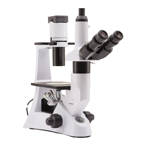
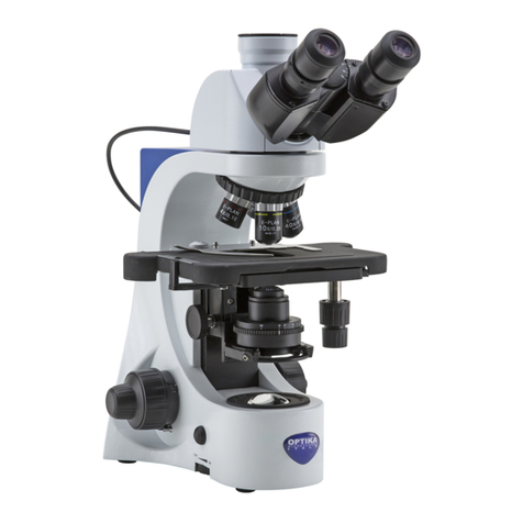
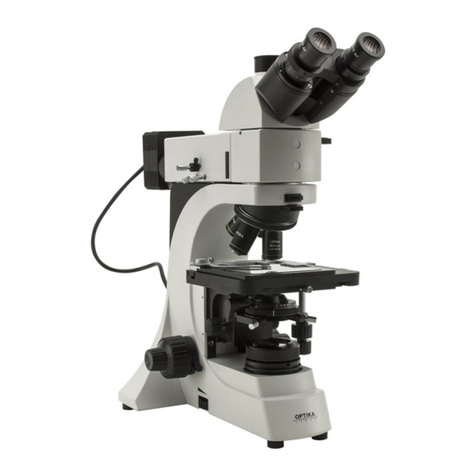
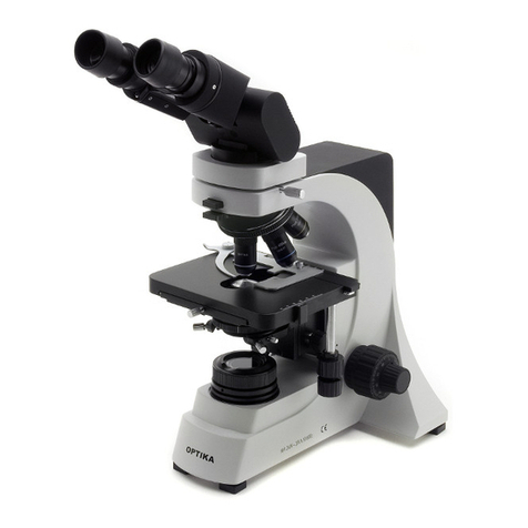
Optika B-800 User manual

B-800
OPERATION MANUAL
GUIDA UTENTE
MANUAL DE INSTRUCCIONES
MANUEL D’INSTRUCTIONS
BEDIENUNGSANLEITUNG


Page 3
INDEX
1.0 SAFETY GUIDELINES page 4
2.0 DESCRIPTION page 5
3.0 UNPACKING AND ASSEMBLY page 7
4.0 USING THE MICROSCOPE page 8
5.0 MAINTENANCE page 10
6.0 ELECTRICAL SPECIFICATION page 11
7.0 RECOVERY AND RECYCLING page 11

Page 4
This microscope is a scientic precision instrument designed to last for many years with a minimum of main-
tenance. It is built to high optical and mechanical standards and to withstand daily use.
Optika reminds you that this manual contains important information on safety and maintenance, and that it
must therefore be made accessible to the instrument users.
Optika declines any responsibility deriving from instrument uses that do not comply with this manual.
Safety guidelines
This manual contains important information and warnings regarding safety about installation, use and
maintenance of the microscope. Please read this manual carefully before using the equipment. To
ensure safe use, the user must read and follow all instructions in this manual. OPTIKA products are
designed for safe use in normal operating conditions. The equipment and accessories described in
the manual are manufactured and tested according to industry standards for safety instrumentation
laboratory. Misuse can cause personal injury or damage to the instrument. Keep this manual at hand
close to the instrument, for an easy consultation.
Electrical safety
Before connecting the power cord to wall outlet, ensure that your mains voltage for your region corre-
sponds to the voltage supply of the instrument, and that the illuminator’s switch is in position OFF. The
user must observe the safety regulations in force in his region. The instrument is equipped with CE
safety marking, in any case the user has full responsibility concerning the safe use of that instrument.
Warning/Caution symbols used in this manual
The user should be aware of safety aspects when using the instrument. Warning or hazard symbols
are shown below. These symbols are used in this manual.
Follow the instructions on this symbol to avoid possible severe personal injuries.
Warning of use; the incorrect operation on the instrument can cause damages
to the person or instrument.
Possibility of electric shock.
Attention: high temperature surfaces. Avoid direct contact.
Technical notes or usage tips.
1.0 SAFETY GUIDELINES

Page 5
2.0 DESCRIPTION
OBJECTIVE
SLIDE CLAMP
COARSE FOCUSING
KNOB
FINE FOCUSING
KNOB
IRIS DIAPHRAGM
STAGE
NOSEPIECE
EYEPIECES
LIGHT PATH
SELECTOR LEVER
TENSION
ADJUSTMENT
KNOB
DIOPTRIC ADJUSTEMENT
RING
FOCUS STOP KNOB

Page 6
2.0 DESCRIPTION
FILTER SLOT
PHOTO/VIDEO
OUTPUT
PHASE RING CENTRING
SCREWS
PHASE CONTRAST
CONDENSER
(B-800PH MODEL)
CONDENSER-CENTRING
SCREWS
X-Y TRANSLATION
KNOBS
ON/OFF SWITCH
CONDENSER
ADJUSTMENT
KNOB
BRIGHTNESS
ADJUSTMENT
FIELD DIAPHRAGM

Page 7
FILTER SLOT
3.0 UNPACKING AND ASSEMBLY
3.1 The microscope is housed in a moulded Styrofoam container. Remove the tape from the edge of the
container and lift the top half of the container. Take some care to avoid that the optical items (objecti-
ves and eyepieces) fall out and get damaged. Using both hands (one around the arm and one around
the base), lift the microscope from the container and put it on a stable desk.
3.2 The objectives are already mounted on the nosepiece or located in individual protective vials (depen-
ding on the model). Remove the objectives from the vials and insert them into the microscope nose-
piece in the order from the lowest magnication to the highest.
3.3 Place the observation head onto the top of the arm and tighten the lock-screw with the provided
wrench. Insert the eyepieces into the eye tubes.
Connect the cable from the provided external power supply into the socket on the back of the base.
The power supply should be used only on network sockets equipped with adequate grounding.
Once positioned and installed with the necessary components, the microscope is ready to be used.
Your microscope is a laboratory instrument designed to last. Handle it always carefully and avoid
abrupt vibrations or shocks. Always disconnect the power supply from the wall socket when not in use
for long time, while you clean it or when you perform any maintenance.
AVOID DISASSEMBLING THE INSTRUMENT
Do not disassemble the instrument. This entails the cancellation of the warranty and may cause mal-
function.

Page 8
4.1 Adjust the observation head
Loosen the lock-screw, turn the observation head to a comfortable position for observation, and then
lock the lock-screw.
4.2 Place the specimen on the stage
Lock the specimen slide on the mechanical stage using the slide clamp. Ensure that the specimen is
centred over the stage opening by adjusting the X-Y translation knobs of the stage.
4.3 Lamp settings
The microscope is tted with a 3,5W high-efciency white led source. Insert the plug of the power
supply into the power socket and turn on the ON/OFF switch on the side of the main body. Turn the
brightness adjustment knob to a brightness suitable for observation.
4.4 Adjust interpupillary distance
Hold the right and left parts of the observation head with both hands and adjust the interpupillary
distance by turning the two parts until one circle of light can be seen. After nishing the interpupillary
adjustment, turn the dioptric adjustment ring on the left eyetube to the “0” position on the graduated
line.
4.5 Focus and diopter adjustment
Loosen the focus-stop knob, rotate the coarse focusing knob to bring the slide into focus with an
objective with a low magnication. Adjust the ne focusing knob to get the image sharp and clear whi-
le observing with your right eye, then turn the left dioptric adjustment ring to a sharp and clear image
also with the other eye.
Turn the tension-adjust-knob to get a suitable tension for the focus system. When the image is in fo-
cus, turn the nosepiece to choose the objective you need.
4.6 Condenser adjustment
Turn the condenser adjustment knob to move the condenser up or down for a clear and uniform sam-
ple illumination. The two condenser centring screws can be used to centre the condenser.
4.7 Set the numerical aperture
Adjust the aperture of the iris diaphragm to set the numerical aperture of the illuminator, thus control-
ling image contrast and resolution.
4.8 Field diaphragm
Adjust the eld diaphragm to align the system and to control stray light.
4.9 Additional lters
The colored lter (green) can be inserted directly above the eld diaphragm. The use of the green lter
is recommended for phase contrast observations.
4.10 Using the polarizer (optional)
The polarizing set consists of two lters: the analyzer and the polarizer. The analyzer is placed in the
lter slot under the head, while the polarizer directly above the eld diaphragm.
4.0 USING THE MICROSCOPE
Page 9
4.0 USING THE MICROSCOPE
4.11 Photo and Video capturing
B-800 has a dedicated trinocular head that allows to capture images via a photo/video adaptor, spe-
cic for each model of camera. Before taking a picture or lming video, pull out the light path selec-
tor lever (on the right of the optical head).
Please refer to the adaptor and camera manuals for further details.
4.12 Using the phase contrast set
Phase contrast is provided as standard in B-800PH model, while it’s optional for B-800BF model.
The phase contrast set has 4 objectives for phase contrast and one condenser with the dedicated
rings of phase. To use the phase contrast, remove the brighteld condenser from the microscope
and replace it with the phase contrast condenser.
In order to obtain a correct phase contrast view, the phase contrast rings must be
aligned using the alignment screws placed on both sides of the condenser.
Follow these steps:
Select an objective by rotating the nosepiece (it’s suggested to start with the 10X
objective), and focus on a slide under brighteld illumination (“BF” or “0” position on
the condenser wheel).
Insert the phase ring to be realigned (by rotating the wheel on the condenser until
you read the corresponding number, e.g. “10”).
Remove an eyepiece, and replace it with the centring telescope.
Focus the centring telescope, without touching the microscope focus, in order to
focus the phase rings (one bright ring and one darker ring, as picture A).
Turning the two phase ring centring screws, move the bright ring, so that it is com-
pletely contained in the dark ring. (see picture B.)
Remove the telescope, and replace the eyepiece.
4.13 Darkeld condenser (optional)
For darkeld observation, the Abbe condenser in standard equipment must be replaced
with a special condenser for darkeld, as showed in the picture.

Page 10
5.1 Always think about
- The following environment is required:
Indoor temperature: 0-40°C; Maximum relative humidity: 85 % (non condensing).
- Keep the microscope away from dust and shocks while in use.
- Turn off the light immediately after use.
- Use a soft lens tissue to clean the optics after use.
- Only if needed, use a cloth moistened with water and a mild detergent, rinsing with water and drying
immediately with a lint-free cloth.
- After use, cover the microscope with the included dust-cover, and keep it in a dry and clean place.
5.2 Do not!
- Wipe the surface of any optical items with your hands. Fingerprints can damage the optics.
- Use solvents, neither on the microscope, nor on the optics.
- Disassemble objective or eyepieces to attempt to clean them.
- Mishandle or impose unnecessary force on the microscope.
- Clean the unit with volatile solvents or abrasive cleaners.
- Attempt to service the microscope yourself.
B-800: the high-efciency white LED source in B-800 is designed to last many years without any per-
formance decrease. Never try to replace it with another kind of LED source. In case of malfunctioning
contact OPTIKA service.
5.3 If you need to send the microscope to Optika for maintenance, please use the original packaging.
5.0 MAINTENANCE
Page 11
6.0 ELECTRICAL SPECIFICATION
Power supply: External power supply
- Input: 90-240Vac, 50/60 Hz
- Output: 6Vdc, 2,5A
Light source: 3,5W high-efciency X-LED
7.0 RECOVERY AND RECYCLING
Art.13 Dlsg 25 july 2005 N°151. “According to directives 2002/95/EC, 2002/96/EC and 2003/108/EC relating
to the reduction in the use of hazardous substances in electrical and electronic equipment and waste dispo-
sal.”
The basket symbol on equipment or on its box indicates that the product at the end of its useful life should be
collected separately from other waste.
The separate collection of this equipment at the end of its lifetime is organized and managed by
the producer. The user will have to contact the manufacturer and follow the rules that he adop-
ted for end-of-life equipment collection. The collection of the equipment for recycling, treatment
and environmentally compatible disposal, helps to prevent possible adverse effects on the environ-
ment and health and promotes reuse and/or recycling of materials of the equipment. Improper dispo-
sal of the product involves the application of administrative penalties as provided by the laws in force.


Pagina 13
INDICE
1.0 INDICAZIONI PER LA SICUREZZA pag. 14
2.0 DESCRIZIONE pag. 15
3.0 DISIMBALLAGGIO E INSTALLAZIONE DEL MICROSCOPIO pag. 17
4.0 UTILIZZO DEL MICROSCOPIO pag. 19
5.0 MANUTENZIONE DEL MICROSCOPIO pag. 20
6.0 CARATTERISTICHE ELETTRICHE pag. 21
7.0 MISURE ECOLOGICHE pag. 21

Pagina 14
Il presente microscopio è uno strumento scientico di precisione studiato per durare molti anni con una manu-
tenzione minima, essendo costruito secondo i migliori standard ottici e meccanici e progettato per un utilizzo
quotidiano.
Optika ricorda che il presente manuale contiene informazioni importanti per un uso sicuro e una corretta ma-
nutenzione dello strumento. Esso deve quindi essere accessibile a chiunque lo utilizzi.
Optika declina ogni responsabilità derivante da un uso improprio dei suoi strumenti non indicato dalla pre-
sente guida.
Avvertenze di sicurezza
Questo manuale contiene importanti informazioni e avvertenze riguardanti la sicurezza riguardo l’in-
stallazione, l’utilizzo e la manutenzione del microscopio. Si raccomanda di leggere attentamente il
manuale prima di qualsiasi utilizzo dello strumento. Per assicurare un utilizzo sicuro l’utente deve
leggere e seguire tutte le istruzioni poste nel presente manuale.
I prodotti OPTIKA sono studiati per un utilizzo sicuro in condizioni operative normali. Lo strumento e
gli accessori descritti nel manuale sono realizzati e testati secondo standard industriali di sicurezza
per strumentazione da laboratorio.
L’utilizzo non corretto può causare lesioni alla persona o danni allo strumento.
Mantenere questo manuale a portata di mano vicino allo strumento, per una facile consultazione.
Precauzioni di sicurezza elettrica
Prima di collegare il cavo di alimentazione alla presa di rete, assicurarsi che la tensione di rete della
vostra regione corrisponda alla tensione di alimentazione dello strumento, e che l’interruttore dell’illu-
minatore sia in posizione spenta.
L’utente deve osservare la regolamentazione riguardante la sicurezza in vigore nel proprio Stato. Lo
strumento è dotato di marcatura di sicurezza CE, in ogni caso l’utente ha piena responsabilità riguar-
do all’utilizzo sicuro dello strumento stesso.
Simboli di avvertenza/pericolo usati nel manuale
L’utente deve essere a conoscenza degli aspetti legati alla sicurezza nel momento in cui utilizza lo
strumento. I simboli di avvertenza o pericolo sono indicati sotto. Tali simboli sono utilizzati in questo
manuale di istruzioni.
Seguire le istruzioni contrassegnate da questo simbolo per evitare possibili gra-
vi danni alle persone.
Avvertimento di utilizzo; la non corretta operazione sullo strumento può causare
danni alla persona o allo strumento.
Possibilità di shock elettrico.
Attenzione: superci ad elevata temperatura. Evitare il contatto diretto.
Note tecniche o consigli di utilizzo.
1.0 INDICAZIONI PER LA SICUREZZA

Pagina 15
2.0 DESCRIZIONE
OBETTIVI
PINZETTA
FOCUS
MACROMETRICO
FOCUS
MICROMETRICO
DIAFRAMMA DI
APERTURA
TAVOLINO
REVOLVER
OCULARI
LEVETTA PER
SELEZIONE PERCORSO
OTTICO
REGOLAZIONE
TENSIONE
FOCUS
COMPENSAZIONE
DIOTTRICA
BLOCCO FOCUS

Pagina 16
2.0 DESCRIZIONE
SLOT FILTRO
USCITA FOTO/VIDEO
VITI DI CENTRAGGIO
ANELLI DI FASE
CONDENSATORE
DI FASE
(MODELLO B-800PH)
VITI DI CENTRAGGIO
CONDENSATORE
MANOPOLA
TRASLAZIONE X-Y
ON/OFF SWITCH REGOLAZIONE
ALTEZZA
CONDENSATORE REGOLAZIONE
INTENSITA’
DIAFRAMMA
DI CAMPO

Pagina 17
3.0 DISIMBALLAGGIO E INSTALLAZIONE DEL MICROSCOPIO
3.1 Il microscopio si trova in un imballo in polistirolo espanso stampato. Dopo aver aperto la scatola, sol-
levare la parte superiore dell’imballo. Fare attenzione a non far cadere e danneggiare le componenti
ottiche (obiettivi e oculari). Estrarre il microscopio dal suo imballo con entrambe le mani (una sosterrà
il braccio e l’altra la base) e appoggiarlo su un piano stabile.
3.2 Gli obiettivi sono già montati sul revolver oppure confezionati singolarmente in custodie di protezione
(a seconda del modello). Togliere gli obiettivi dalle loro custodie e inserirli nel revolver portaobiettivi
dall’obiettivo con il minore potere di ingrandimento a quello con il maggiore.
3.3 Posizionare la testata di osservazione sul braccio dello stativo e stringere la vite di ssaggio con la
chiave in dotazione. Inserire gli oculari negli appositi tubi della testa.
Connettere il cavo dall’alimentatore esterno in dotazione nella presa posta sul retro dello stativo.
L’alimentatore esterno deve essere utilizzato solo su prese di rete dotate di adeguata messa a terra.
Una volta posizionato e installato con i necessari componenti, il microscopio è pronto per l’utilizzo.
Il vostro microscopio è uno strumento da laboratorio progettato per durare a lungo. Maneggiatelo
sempre con cura ed abitate brusche vibrazioni o colpi. Scollegare sempre l’alimentatore esterno dalla
presa di rete quando non viene utilizzato per lunghi tempi, mentre si pulisce lo strumento o quando
si esegue una qualsiasi manutenzione.
EVITARE DI SMONTARE LO STRUMENTO
Non disassemblare lo strumento. Questo comporta l’annullamento della garanzia e potrebbe causare
malfunzionamenti.
SLOT FILTRO

Pagina 18
4.1 Regolazione della testata di osservazione
Allentare la vite di serraggio, ruotare la testata no a trovare una posizione comoda per l’osservazione
e quindi avvitarla nuovamente.
4.2 Posizionamento del vetrino sul tavolo portapreparati
Fissare il vetrino con preparato al piano meccanico mediante l’apposita pinzetta per sostegno cam-
pioni. Regolando le manopole coassiali del piano portaoggetti, assicurarsi che il vetrino si trovi al
centro del campo di osservazione.
4.3 Impostazione della luce
Il microscopio è dotato di un illuminatore LED da 3,5W ad alta efcenza. Inserire lo spinotto dell’a-
limentatore nella presa di alimentazione e premere il pulsante di accensione posto sul anco dello
stativo. Con la manopola di regolazione della luminosità si metta a punto la luminosità migliore per
l’osservazione.
4.4 Regolazione della distanza interpupillare
Regolare la distanza interpupillare dei portaoculari sulla testata no ad ottenere la visione di un unico
campo luminoso circolare tenendo ferme le parti destra e sinistra della testata di osservazione. Termi-
nata la regolazione, ruotare l’anello di compensazione diottrica sull’oculare sinistro no a raggiungere
lo “0” (zero) sulla scala graduata.
4.5 Regolazione della messa a fuoco e regolazione diottrica
Allentare il blocco della messa a fuoco, ruotare la manopola di messa a fuoco macrometrica per fo-
calizzare il vetrino con un obiettivo a basso potere di ingrandimento. Regolare la manopola di messa
a fuoco micrometrica no ad ottenere un’immagine chiara e denita osservando con l’occhio destro,
quindi ruotare l’anello di compensazione diottrica no ad ottenere un’immagine denita anche con
l’occhio sinistro. Con la manopola di regolazione della tensione impostare la tensione migliore per la
messa a fuoco. Quando l’immagine è a fuoco, scegliere l’obiettivo desiderato sul revolver portaobiet-
tivi.
4.6 Regolazione del condensatore
Alzare o abbassare il condensatore mediante l’apposita manopola per ottenere un’illuminazione chia-
ra e uniforme dell’oggetto. Per centrare il condensatore servirsi delle due viti di centraggio.
4.7 Impostazione dell’apertura numerica
Regolare l’apertura del diaframma a iride per impostare l’apertura numerica dell’illuminatore, control-
lando così contrasto e risoluzione dell’immagine.
4.8 Diaframma di campo
Regolare il diaframma di campo per allineare il sistema e controllare la luce diffusa.
4.9 Filtri aggiuntivi
Il ltro monocromatico verde può essere inserito direttamente sopra il diaframma di campo. Si consi-
glia l’uso del ltro verde per osservazioni a contrasto di fase.
4.0 UTILIZZO DEL MICROSCOPIO

Pagina 19
4.0 UTILIZZO DEL MICROSCOPIO
4.10 Utilizzo del polarizzatore (opzionale)
Il kit polarizzante è composto da due ltri: l’analizzatore e il polarizzatore. L’analizzatore si posiziona
nello slot sotto la testata, mentre il polarizzatore direttamente sopra il diaframma di campo.
4.11 Acquisizione di video/foto (opzionale)
La serie B-800 è dotata di testata di osservazione trinoculare, che consente di acquisire immagini
tramite un adattatore specico per ogni modello di videocamera. Prima di procedere all’acquisizione
di immagini video/foto, estrarre la levetta di selezione del percorso ottico (sulla destra della testata).
Per ulteriori dettagli si rimanda ai manuali delle videocamere.
4.12 Utilizzo del kit per contrasto di fase
Il contrasto di fase è fornito come standard nel modello B-800PH, mentre è opzionale per la versione
B-800BF. Questo kit contiene 4 obiettivi per il contrasto di fase e un condensatore con gli appositi
anelli di fase. Per utilizzare il kit, togliere il condensatore di Abbe presente sul microscopio e sostitu-
irlo con l’apposito condensatore.
Per ottenere una corretta visione in contrasto di fase, gli anelli di fase devo-
no essere allineati usando le viti di centraggio poste ai lati del condensatore.
Seguire questi passi:
Scegliere un obiettivo ruotando il revolver (si suggerisce di iniziare con l’o-
biettivo 10x), e mettere a fuoco un vetrino con illuminazione in campo chiaro
(posizione “BF” o “0” della ghiera del condensatore).
Inserire l’anello di fase da allineare (ruotando la ghiera del condensatore
no a leggere il numero corrispondente all’obiettivo (ad es. “10”)).
Rimuovere un oculare, e inserire il telescopio di centratura. Mettere a
fuoco il telescopio, senza variare la messa a fuoco del microscopio, no ad
ottenere una visione chiara degli anelli di fase (uno più chiaro ed uno più
scuro, si veda immagine A).
Premendo e ruotando le due viti di centratura degli anelli di fase, muovere l’anello più chiaro in modo
che sia completamente contenuto nell’anello più scuro (come da immagine B).
Togliere il telescopio e rimettere l’oculare.
4.13 Condensatore campo oscuro (opzionale)
Per l’osservazione del campo oscuro, sostituire il condensatore di Abbe (dotazione standard) con il
condensatore speciale per campo oscuro.

Pagina 20
5.1 Da ricordare:
- Ambiente di lavoro con temperatura interna: 0-40°C.
- Umidità relativa massima: 85% (in assenza di condensa).
- Durante l’uso proteggere il microscopio da polvere e urti.
- Spegnere la luce immediatamente dopo l’uso.
- Dopo l’uso pulire le ottiche con un apposito panno morbido.
- Solo se necessario, servirsi di un panno inumidito con acqua e un detersivo neutro, risciacquando
accuratamente con acqua e asciugando immediatamente con un panno non slacciato.
- Dopo l’uso coprire il microscopio con la custodia antipolvere in dotazione e tenere in un luogo asciutto
e pulito.
5.2 Da evitare:
- Non stronare la supercie di nessun componente ottico con le mani perché le impronte digitali pos-
sono danneggiare le ottiche.
- Non utilizzare solventi né sul microscopio né sulle ottiche.
- Non smontare gli obiettivi o gli oculari per cercare di pulirli.
- Maneggiare con cura e non adoperare inutile forza sul microscopio.
- Non pulire lo strumento con solventi volatili o agenti pulenti abrasivi.
- Non cercare di provvedere da soli alla manutenzione.
B-800: la sorgente LED bianca ad alta efcenza nel microscopio B-800 è studiata per non subire nes-
suna perdità in qualità e in prestazioni per diversi anni.
In caso di malfunzionamento contattare il servizio tecnico OPTIKA.
5.3 Si prega di utilizzare l’imballaggio originale nel caso in cui fosse necessario rispedire il microscopio a
Optika per la manutenzione.
5.0 MANUTENZIONE DEL MICROSCOPIO
Table of contents
Languages:
Other Optika Microscope manuals

Optika
Optika B-500DK User manual

Optika
Optika B-600 MET User manual

Optika
Optika B-150POL-M User manual

Optika
Optika SZN Series User manual

Optika
Optika B-500TiFL User manual

Optika
Optika ST-50Led User manual

Optika
Optika B-1000 POL User manual

Optika
Optika B-500POL User manual

Optika
Optika XZ-2 User manual

Optika
Optika B-290 User manual

Optika
Optika SZM User manual

Optika
Optika B-510 Series User manual

Optika
Optika B-510 Series User manual

Optika
Optika B-810 Series User manual

Optika
Optika XDS-3 User manual

Optika
Optika B-150POL User manual

Optika
Optika B-180 User manual

Optika
Optika B-150D-MRPL Mounting instructions

Optika
Optika B-1000 Series User manual

Optika
Optika B-190 User manual