manuals.online logo
Brands
  1. Home
  2. •
  3. Brands
  4. •
  5. ORiNG
  6. •
  7. Network Router
  8. •
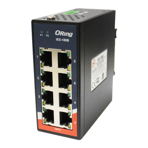
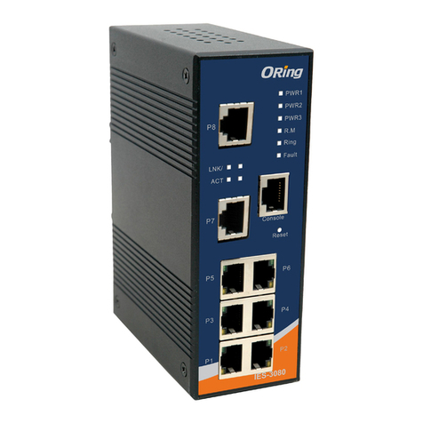
  9. ORiNG IES-1080A User manual

ORiNG IES-1080A User manual

1
2
3
4
5
6
7
8
P1 P2 Fau lt
IES-1080A
PWR- 1PWR- 2
V2+ V2 - V1+ V1 -
G
1A@2 4V DC 12-4 8V
Quick Installation Guide
Version 2.1
Quick Installation Guide
Introduction
PRINTED ON RECYCLED PAPER
Preparation
Before you begin installing the switch, make sure you have all of the package
contents available and a PC with Microsoft Internet Explorer 6.0 or later, for
using web-based system management tools.
Elevated Operating Ambient: If installed in a closed or multi-unit rack
assembly, the operating ambient temperature of the rack environment may be
greater than room ambient. Therefore, consideration should be given to
installing the equipment in an environment compatible with the maximum
ambient temperature (Tma) specified by the manufacturer.
Reduced Air Flow: Installation of the equipment in a rack should be such
that the amount of air flow required for safe operation of the equipment is
not compromised.
Safety & Warnings
Dimension
Panel Layouts
1. PWR indicators
2. Faulty relay indicator
3. LAN port link/act indicator
4. LAN port duplex indicator
5. LAN ports
Package Contents
Front View
The device is shipped with the following items. If any of these items is
missing or damaged, please contact your customer service representative for
assistance.
Installation
Step 1: Slant the switch and screw the Din-rail kit onto the back of the switch, right in
the middle of the back panel.
Step 2: Slide the switch onto a DIN-rail from the Din-rail kit and make sure the switch
clicks into the rail firmly.
DIN-rail Installation
Step 1: Screw the wall-mount kit onto the rear panel of the switch. A total of six
screws are required, as shown below.
Step 2: Use the switch, with wall mount plates attached, as a guide to mark the
correct locations of the four screws.
Step 3: Insert a screw head through the large parts of the keyhole-shaped apertures,
and then slide the switch downwards. Tighten the screws for added stability.
Wall-mounting
Q I G 1907-200-E1080AXXX2-FX011
Mechanical Loading: Mounting of the equipment in the rack should be such that a
hazardous condition is not achieved due to uneven mechanical loading.
Circuit Overloading: Consideration should be given to the connection of the equipment to
the supply circuit and the effect that overloading of the circuits might have on overcurrent
protection and supply wiring. Appropriate consideration of equipment nameplate ratings
should be used when addressing this concern.
Network Connection
The switch provides standard Ethernet ports. According to the link type, the switch uses
CAT 3,4,5,5e UTP cables to connect to any other network devices (PCs, servers,
switches, routers, or hubs). Please refer to the following table for cable
specifications.
Cable Types and Specifications:
Cable
Type
Max. Length
Connector
10BASE-T Cat. 3, 4, 5 100-ohm UTP 100 m (328 ft) RJ-45
100BASE-TX Cat. 5 100-ohm UTP UTP 100 m (328 ft) RJ-45
Unit =mm (Tolerance ±0.5mm)
Features
Contents
Wall-mount Kit
DIN-rail Kit
IES-1080A
Pictures Number
X 2
X 1
QIG X 1
X 1
6-pin terminal block X 1
3
5
4
Rear View
1
1. Din-rail screw holes
Top Panel
1. Wall-mount screw holes
2. Terminal blocks: PWR1, PWR2
, Relay
3. DIP Switch
4. Ground wire.
2 3
4
1
1
is unmanaged Ethernet Switch with 8x10/100Base-T(X) ports and extendedIES-1080A
operating temperature range from -40 C to 75 C for the harsh environments. The
o o
enclosure designed with compact size and a robust housing; it can help you to easily
installed.
Support 8 ports 10/100Base-T(X)
Support auto-negotiation and auto-MDI/MDI-X
Support store and forward transmission
Support flow control
Provide Relay output
Compact size for easily installation
Rigid IP-30 housing design
DIN-Rail and wall mounting enable
94.9
68.15
8.0
14.0 6.05
25.0
50.0
25.5
8.5
25.6
24.3
Ø5.9
Ø3.0
26.1
144.3
12.3
13.1
24.3
Ø4.0
12
Industrial Unmanaged Switch
S W I T C H
I N D U S T R I A L
1
2
3
4
5
6
7
8
P1 P2 Faul t
IES-1080A
1
2
3
4
5
6
7
8
P1 P2 Faul t
IES-1080A
IES-1080A
IES-1080A
Q I G Quick Installation Guide
PRINTED ON RECYCLED PAPER
Quick Installation Guide
Q I G
DIP Switch Setting
Wiring
The switch supports dual redundant power supplies, Power Supply1
(PWR1) and Power Supply 2 (PWR2). The connections for PWR1,
PWR2 and the RELAY are located on the terminal block.
STEP 1: Insert the negative/positive wires into the V-/V+ terminals,
respectively.
STEP 2: To keep the DC wires from pulling loose, use a small flat-
blade screwdriver to tighten the wire-clamp screws on the front of the
terminal block connector.
PWR-1PWR-2 1A@24V
V2- V2+ V1- V1+
Power inputs
The two sets of relay contacts of the 6-pin terminal block connector are used to detect user-
configured events. The two wires attached to the fault contacts form an close circuit when a
user-configured event is triggered. If a user-configured event does not occur, the fault
circuit remains opened.
Relay contact
Grounding and wire routing help limit the effects of noise due to electromagnetic
interference (EMI). Run the ground connection from the ground screws to the grounding
surface prior to connecting devices.
Grounding
Configurations
After installing the switch, the green power LED should turn on. Please refer
to the following tablet for LED indication.
Specifications
LED
Color
Status
Description
P1 Green On DC power 1 activated
P2 Green On DC power 2 activated
Fault Amber On Power failure
10/100Base-T(X) Ethernet ports
LNK/ACT Green On Port is linked
Duplex Amber
On Port link up for full duplex
Off Port link up for half duplex
For pin assignments for different types of cables, please refer to the following
tables.
ORing Industrial Networking Corp.
Copyright© 2010 ORing
All rights reserved.
TEL: +886-2-2218-1066
FAX: +886-2-2218-1014
Website: www.oringnet.com
E-mail: support@oringnet.com
Version 2.1
DIP-2
OFF
OFF
ON
DIP-1
Power failure relay alarm disabled
PWR-1 failure, relay alarm enabled
PWR-2 failure, relay alarm enabled
OFF
ON
OFF
Description
ON PWR-1 or PWR-2 failure,
relay alarm enabled
ON
10/100Base-T(X) RJ-45
Pin Number Assignment
1 TD+
2 TD-
3 RD+
4 Not used
5 Not used
6 RD-
7 Not used
8 Not used
Note: “+” and “-” signs represent the polarity of the wires
that make up each wire pair.
ORing Switch Model
Physical Ports
Technology
Ethernet Standards
LED Indicators
Green: Power LED x2Powe r i ndicato r
10/100Base-T(X) Port in RJ45
Auto MDI/MDI X
IEEE 802.3 for 10Base-T,
IEEE 802.3u for 100Base-TX
IEEE 802.3x for Flow cont rol
Processing Store-and-Forward
Environmental
-40 to 85 C (-4 0 t o 185 F)
o o
Storage Temperature
Operating Temperature
5% to 95% Non-condensingOperating Humidity
Regulatory approvals
CE EMC (EN 55024, EN 55032), FC C Part 15 BEMC
EN 55024 (IEC/EN 61000-4- 2 (ESD: Con tact 4KV, Air 8K V ), IEC/E N 6 1000-4 - 3 (RS: 3V)
IEC/EN 61000-4-4 (EF T Power 0.5KV, Signal 0. 5 KV),
IEC/EN 61000-4-5 (Surge : Power 0.5KV, Signal 1KV) , I EC/EN 61 0 00-4-6 ( C S: 3V),
IEC/EN 61000-4-8(PFM F ), IEC/E N 61000-4 - 11 (DIP))
EMS
IEC60068-2-27Shock
IEC60068-2-32
IEC60068-2-6Vibration
Free Fall
MTBF
2,439,118hrs
-40 to 75 C (-4 0 t o 167 F)
o o
Amber: Indicate PWR1 or PWR 2 f ailure
Fault indicator
Fault contact
Relay Relay output to carr y c apacity of 1A a t 2 4 VDC
Power
Redu n dant Inp u t power
Powe r c onsump t ion(Typ.) <3.7Watts, 0.23 A-0.07A
Overload current protectio n
Reverse p o larity pro t ection
Present
Present
Physical Characteristic
Enclosure IP-30 Metal
Dimension (W x D x H)
Weight (g) 391 g
Dual 12~48VDC on 6-pin termi n al block
26.1(W)x94.9(D)x144 .3(H) mm (1 . 03x3.74 x5.68in c h.)
10/100Base-T(X) RJ45 Port
Indicator
Upper LED for Link/Act indic ator: Gre en for Link / Act
Lower LED for duplex indicat or, Amber for fu l l duplex, o ff for half du p lex
EN60950-1(LVD)Safety
IES-1080A
8
MAC Table 1K
Packet buf fer 448 Bits
Warranty
5 years
Switch Properties
Switching latency: 7 us
Switching bandwidth: 1.6Gb ps
Throughput (packet per secon d ): 1.19M p ps@64B y tes packet
Hardware Version V2.0
EN 55032, CISPR32, EN 61000- 3-2, EN 610 00-3-3, F C C Part 15 B class AEMI
Industrial Unmanaged Switch
S W I T C H
I N D U S T R I A L
IES-1080A
IES-1080A
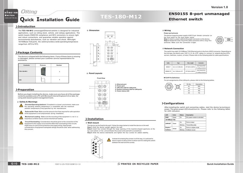
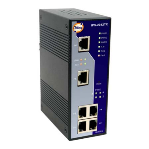
Other manuals for IES-1080A
1

Other ORiNG Network Router manuals

ORiNG RGPS-9084GP-P User manual

ORiNG

ORiNG RGPS-9084GP-P User manual

ORiNG IGS-9122GPM User manual

ORiNG

ORiNG IGS-9122GPM User manual

ORiNG IR-710 User manual

ORiNG

ORiNG IR-710 User manual

ORiNG IES-3080 Series User manual

ORiNG

ORiNG IES-3080 Series User manual

ORiNG TGS-9200-M12-BP2 User manual

ORiNG

ORiNG TGS-9200-M12-BP2 User manual

ORiNG TES-3082GT-M12-BP1 User manual

ORiNG

ORiNG TES-3082GT-M12-BP1 User manual

ORiNG TGAR-1062-M12-3G User manual

ORiNG

ORiNG TGAR-1062-M12-3G User manual

ORiNG IES-2042PA User manual

ORiNG

ORiNG IES-2042PA User manual

ORiNG CPGS-9080-C User manual

ORiNG

ORiNG CPGS-9080-C User manual

ORiNG IES-3062GT User manual

ORiNG

ORiNG IES-3062GT User manual

ORiNG IES-3162GC Series User manual

ORiNG

ORiNG IES-3162GC Series User manual

ORiNG IES-2050A User manual

ORiNG

ORiNG IES-2050A User manual
ORiNG RGPS-92222GCP-NP-LP User manual

ORiNG

ORiNG RGPS-92222GCP-NP-LP User manual

ORiNG RGS-R9004GP+ME-HV User manual

ORiNG

ORiNG RGS-R9004GP+ME-HV User manual

ORiNG RGS-PR9000 User manual

ORiNG

ORiNG RGS-PR9000 User manual

ORiNG IES-180B User manual

ORiNG

ORiNG IES-180B User manual

ORiNG IR-710 User manual

ORiNG

ORiNG IR-710 User manual

ORiNG IAR-630-C User manual

ORiNG

ORiNG IAR-630-C User manual

ORiNG TGRST120-M12X-BP2-WV User manual

ORiNG

ORiNG TGRST120-M12X-BP2-WV User manual

ORiNG IAR-630-D User manual

ORiNG

ORiNG IAR-630-D User manual

ORiNG RES-3242GC User manual

ORiNG

ORiNG RES-3242GC User manual

ORiNG IGS-3032GC User manual

ORiNG

ORiNG IGS-3032GC User manual

ORiNG TGPS-1080-M12-BP2-24V User manual

ORiNG

ORiNG TGPS-1080-M12-BP2-24V User manual

ORiNG IES-2042 Series User manual

ORiNG

ORiNG IES-2042 Series User manual

Popular Network Router manuals by other brands

Enterasys SecureStack A2 A2H124-24P Hardware installation guide

Enterasys

Enterasys SecureStack A2 A2H124-24P Hardware installation guide

Aztech DSL7002GRV(S) installation guide

Aztech

Aztech DSL7002GRV(S) installation guide

Lancom OAP-321-3G Brochure & specs

Lancom

Lancom OAP-321-3G Brochure & specs

D-Link DIR-850L Quick installation guide

D-Link

D-Link DIR-850L Quick installation guide

Cosmote Speedport Plus 2 instruction manual

Cosmote

Cosmote Speedport Plus 2 instruction manual

NetComm NB4 Specifications

NetComm

NetComm NB4 Specifications

D-Link DIR-855L user manual

D-Link

D-Link DIR-855L user manual

EnGenius ECB9500 datasheet

EnGenius

EnGenius ECB9500 datasheet

Linksys WRT320N - Wireless-N Gigabit Router Wireless user guide

Linksys

Linksys WRT320N - Wireless-N Gigabit Router Wireless user guide

WaveRider NCL1170 user guide

WaveRider

WaveRider NCL1170 user guide

Huawei NE40E-M2 Series Hardware description

Huawei

Huawei NE40E-M2 Series Hardware description

Draytek Vigor2110 Series user guide

Draytek

Draytek Vigor2110 Series user guide

HeroSpeed RT811 series Quick operation guide

HeroSpeed

HeroSpeed RT811 series Quick operation guide

Tenda W3002R user guide

Tenda

Tenda W3002R user guide

Huawei Quidway S6500 Series Command manual

Huawei

Huawei Quidway S6500 Series Command manual

Cisco MWR 1900 Hardware installation guide

Cisco

Cisco MWR 1900 Hardware installation guide

Amphenol RES-SCE-AC-4US user manual

Amphenol

Amphenol RES-SCE-AC-4US user manual

Robustel GoRugged R3000 Lite user guide

Robustel

Robustel GoRugged R3000 Lite user guide

manuals.online logo
manuals.online logoBrands
  • About & Mission
  • Contact us
  • Privacy Policy
  • Terms and Conditions

Copyright 2025 Manuals.Online. All Rights Reserved.