manuals.online logo
Brands
  1. Home
  2. •
  3. Brands
  4. •
  5. ORiNG
  6. •
  7. Switch
  8. •
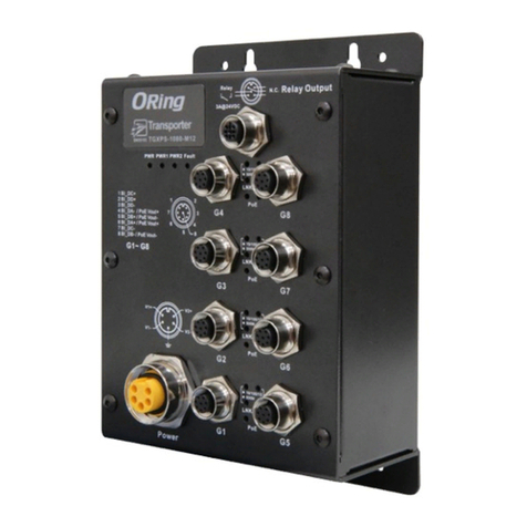
  9. ORiNG TES-250-M12 User manual

ORiNG TES-250-M12 User manual

TES -25 0-M 12
Ring
12- 48 VDC
V-
V+
Tx+ R x+
Tx-Rx-
N.C .
N.C .
N.C .
P1 P 2
P3 P 4
P5 P WR
Ring
Ring
R.M
Quick Installation Guide
Version 1.4
Quick Installation Guide
Introduction
PRINTED ON RECYCLED PAPER
Q I G
ORing's Transporter series Ethernet switches are designed for industrial
TM
applications, such as rolling stock, vehicle, and railway applications. TES-
25 0 -M 1 2 is a l i te - ma n ag e d re d un d an t r in g E th e rn e t sw i tc h w it h
5x10/100Base-T(X) ports which is compliant with EN50155 request. With
completely support of Ethernet redundancy protocol, O-Ring (recovery time <
10ms over 250 units of connection), O-Chain and STP/RSTP (IEEE802.1w/D)
can protect your mission-critical applications from network interruptions or
temporary malfunctions with its fast recovery technologies. It is specifically
designed for the toughest industrial environments. EN50155TES-250-M12
Ethernet switch use M12 connectors to ensure tight, robust connections, and
guarantee reliable operation against environmental disturbances, such as
vibration and shock. can be managed centralized by a powerfulTES-250-M12
windows utility — Open-Vision. In addition, the wide operating temperature
range from -40 C to 70 C can satisfy most of operating environment. The
o o
TES-250-M12 can be easily adopted in almost all kinds of applications and
provides the most rugged solutions for managing your network. Therefore,
the switch is one of the most reliable choices for rolling stock and highly-
managed Ethernet application.
Package Contents
Installation
Wall-mount
The device can be fixed to the wall. Follow the steps below to install the device on the wall.
Step 1: Hold the evice upright against the walld
Step 2: Insert four screws through the large opening of the keyhole-shaped apertures at the
top and bottom of the unit and fasten the screw to the wall with a screwdriver.
Step 3: Slide the evice downwards and tighten the four screws for added stability.d
The device is shipped with the following items. If any of these items is missing
or damaged, please contact your customer service representative for
assistance.
Preparation
Before you begin installing the device, make sure you have all of the package
contents available and a PC with Microsoft Internet Explorer 6.0 or later, for
using web-based system management tools.
Elevated Operating Ambient: If installed in a closed environment, make sure
the operating ambient temperature is compatible with the maximum
ambient temperature (Tma) specified by the manufacturer.
Reduced Air Flow: Make sure the amount of air flow required for safe operation
of the equipment is not compromised during installation.
Mechanical Loading: Make sure the mounting of the equipment is not in a
hazardous condition due to uneven mechanical loading.
Circuit Overloading: Consideration should be given to the connection of the
equipment to the supply circuit and the effect that overloading of the circuits
might have on overcurrent protection and supply wiring. Appropriate
consideration of equipment nameplate ratings should be used when addressing
this concern.
Safety & Warnings
For pin assignments of power, console and relay output ports, please refer to the following tables.
Contents
TES-250-M12
Pictures Number
1
QIG 1
Panel Layouts
Front View
1. Fast Ethernet port
2. LNK/ACT LED for Ethernet ports
3. Ring status LED
4. Power status LED
5. R.M. status LED
6. Power port
Wiring
Grounding
Grounding and wire routing help limit the effects of noise due to electromagnetic interference
(EMI). Run the ground connection from the grounding pin on the power connector to the grounding
surface prior to connecting devices.
Power port pinouts
The switch provides one set of power supply on a M12 5-pin female A-
coding connector. Insert the power cable to the power connector
on the device and rotate the outer ring of the cable connector
until a snug fit is achieved. Make sure the connection is tight.
Network Connection
The switch has five 10/100Base-T(X) Ethernet ports in the form of M12 connector. Depending
on the link type, the switch uses CAT 3, 4, 5,5e UTP cables to connect to network devices (PCs,
servers, switches, routers, or hubs). Please refer to the following table for cable specifications.
1907-200-S250M12XX1-FX014
S w i tc h
E N 5 0 1 5 5
I N D U S T R I A L
1
3
6
5
Instead of screwing the screws in all the way, it is advised to
leave a space of about 2mm to allow room for sliding the switch
between the wall and the screws.
Pin Definition
#1 #2
#3
#4
Configurations
After installing the switch and connecting cables, start the evice by turning ond
power. The green power LED should turn on. Please refer to the following tablet
for LED indication.
V-
V+
N.C.
N.C.
N.C.
10/100Base-T(X) D-coding M12 port
Pin No. Description
#1 TX+
#2 RX+
#3 TX-
#4 RX-
2
4
Cable
Type
Max. Length
Connector
10BASE-T
Cat. 3, 4, 5 100-ohm
UTP 100 m (328 ft)
M12 D-coding connector
100BASE-TX
Cat. 5 100-ohm UTP
UTP 100 m (328 ft)
M12 D-coding connector
LED
Color
Status
Description
Power
Green
On
Power is on
R.M
Green
On
Device operating in Ring Master mode
Ring
Green
On
O-Ring enabled
Blinking
O-Ring structure is broken
10/100Base-T(X) M12 ports
LNK/ACT
Green
On
Port is linked
Off
Port is linked-down
Blinking
Transmitting data
7.50
150.6
44.4
73.9
TES- 250 -M12
Ring
12-4 8 VDC
V-
V+
Tx+ Rx +
Tx-Rx-
N.C.
N.C.
N.C.
P1 P2
P3 P4
P5 PW R
Ring
Ring
R.M
178.2
40.0
142.2
88.9
Ø5.0
Ø8.0
Ø4.0
Dimension Unit =mm (Tolerance ±0.5mm)
TES-250-M12 EN50155 5-port lite-managed
Ethernet switch
TES-250-M12
1
1. Reset button
TES-250-M12
Q I G Quick Installation Guide
PRINTED ON RECYCLED PAPER
Quick Installation Guide
Q I G
S w i tc h
E N 5 0 1 5 5
I N D U S T R I A L
Specifications
ORing Industrial Networking Corp.
Copyright© 2021 ORing
All rights reserved.
TEL: +886-2-2218-1066
FAX: +886-2-2218-1014
Website: www.oringnet.com
E-mail: support@oringnet.com
Version 1.4
EN50155 5-port lite-managed
Ethernet switch
TES-250-M12
Power
Inp ut Power
Power Consumpt ion(Typ.)
12-48VD C on 5-p in fem ale A-codi ng M12 c onnector
3Watts@12 VDC/ 0.25A, 48VD C/0. 062A
Phys ical Characteristic
Enc losur e IP-30
Dim ensio n (W x D x H) 88.9(W) x 40(D ) x 178.2(H) mm ( 3.5 x 1. 57 x 7.0 2 inch. )
Weigh t (g) 454 g
Envi ronmental
-40 to 85 C (-40 to 18 5 F)
o o
Sto rage Tempe ratu re
5% to 95% Non -con densing
Ope rati ng Humi dity
Regu latory Appro vals
CE EMC (EN 55 024, E N 55022), FCC Part 1 5 B, EN 50 155( EN 50121-1, E N 5012 1-3-2)
EMC
EN 55024 (I EC/E N 61000-4-2 ( ESD: C ontac t 4KV) ,
IEC/EN 61 000- 4-3 (RS 80MHz t o 1GHz : 3V/m 1kHz 80% A M),
IEC/EN 61 000- 4-4 (EF T Power 0.5K V, Signa l 0.5K V),
IEC/EN 61 000- 4-5 (Su rge: Powe r 0.5KV, RJ45 1KV ),
IEC/EN 61 000- 4-6 (CS 150K-80 MHz: 3 Vrms 1 kHz 80% A M), IE C/EN 6 1000- 4-8( PFMF),
IEC/EN 61 000- 4-11 (DIP))
EN 50121- 3-2 (I EC/EN 6 1000 -4-2 ( ESD: Co ntac t 6KV) ,
IEC/EN 61 000- 4-3 (RS 80MHz t o 1G/2 .1G/2 .5GH z: 20V /10V/ 5V/m 1 kHz 80 % AM),
IEC/EN 61 000- 4-4 (EF T Power 2KV, Si gnal 2 KV), I EC/EN 6 1000 -4-5 (Surge : Pow er 1KV ),
IEC/EN 61 000- 4-6 (CS 150K-80 MHz: 1 0Vrm s 1kHz 80 % AM), I EC/E N 61000 -4-8 (PFMF),
IEC/EN 61 000- 4-11 (DIP))
EMS
IEC6006 8-2- 27
Sho ck
IEC6006 8-2- 31
IEC6006 8-2- 6
Vib rati on
Fre e Fa ll
Warr anty
5 ye ars
LED In dicators
Power Ind icato r (PWR)
Rin g Maste r Indic ator (R.M.)
Green: Power L ED x 1
Green: In dica te system ope rat ed in O-R ing Ma ster m ode
EN 60950- 1 comp liant
Saf ety
10/ 100Ba se-T(X ) M12 Po rt
Ind icato r
Top Gree n LED fo r Link/ Act in dica tor: Gr een fo r link-u p, Off f or lin k- down, Blink ing fo r Act.
Bottom Gr een LE D for O-Ring fu ncti on indicato r: Gre en for O-Ring e nabl ed, Off for O-R ing di sabled,
Blinkin g for Ri ng is br oken
Overload Curren t Prote ction
Revers e Pola rity Pr otect ion
Present
Present
-40 to 70 C (-40 to 15 8 F)
o o
Ope rati ng Tem pera ture
ORi ng Switch Mo del
10/ 100 Bas e-T(X) Ports i n
M12 Aut o MDI/M DIX 5 x M12 c onnecto r (4-pin M1 2 female D- coding)
Phys ical Ports
Tech nology
Eth ernet S tanda rds
IEE E 802.3 f or 10Ba se-T
IEE E 802.3 u for 100 Base-T X
IEE E 802.3 x for Flo w control
IEE E 802.1 D for STP ( Spanning Tre e Proto col)
IEE E 802.1 w for RST P (Rap id Spann ing Tree Prot ocol)
IEE E 802.1 AB for LL DP (Lin k Layer Discovery Pr otoco l)
TES -250-M1 2
2K
MAC Tabl e
1Mb its
Sto re-a nd-Forwar d
Pro cessi ng
Sw itchi ng laten cy: <7 µs
Sw itchi ng bandw idth: 1 Gbps
Thr oughp ut (pac ket per s econd ): 744Kpps@64 Bytes p acket
VLA N: port-bas ed
Sw itch Pr operti es
Ena ble/D isabl e ports
VLA N to segr egate a nd secu re netwo rk tra ffic
SNM P v3 encr ypted a uthenticati on and ac cess se curity
Sec urity Feat ures
STP /RSTP ( IEEE 80 2.1D/w )
Redundant Ring ( O-Rin g) with recove ry time l ess tha n 10ms over 250 units
Port configuration , statu s, statistics , monit oring , securi ty
Sof twar e Feat ures
O-R ing
O-C hain
Fast re cove ry
STP
RST P
Net work Redund ancy
Packet B uffer S ize
Rese t Function
Reset Button < 5 sec: Sys tem re boot, > 5 s ec: Fact ory de fault
EN 55032, C ISPR 32, EN 61000- 3-2, E N 61000-3-3 , FCC Part 15 B c lass A
EMI
EN 50155 (I EC 613 73)
Oth er
MTBF
1,437,9 90 hrs .
TES-250-M12
Other ORiNG Switch manuals

ORiNG RES-3242GC User manual

ORiNG

ORiNG RES-3242GC User manual

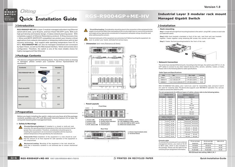
ORiNG RGS-R9004GP+ME-HV User manual

ORiNG

ORiNG RGS-R9004GP+ME-HV User manual

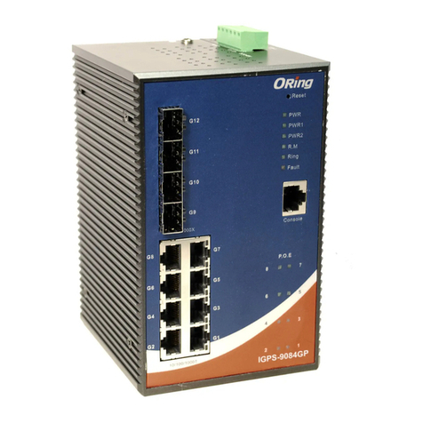
ORiNG IGPS-9084GP-LA User manual

ORiNG

ORiNG IGPS-9084GP-LA User manual

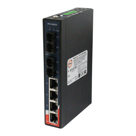
ORiNG IPS-1042FA-MM-SC User manual

ORiNG

ORiNG IPS-1042FA-MM-SC User manual

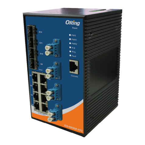
ORiNG IGS-9084GP-FB2 User manual

ORiNG

ORiNG IGS-9084GP-FB2 User manual

ORiNG TGPS-9168GT-M12 User manual

ORiNG

ORiNG TGPS-9168GT-M12 User manual

ORiNG IES-2060 Series User manual

ORiNG

ORiNG IES-2060 Series User manual

ORiNG IES-180-L User manual

ORiNG

ORiNG IES-180-L User manual

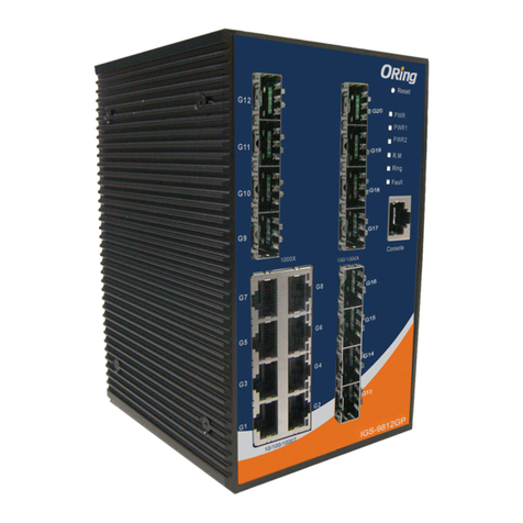
ORiNG IGS-9812GP User manual

ORiNG

ORiNG IGS-9812GP User manual

ORiNG TGPS-9084GT-M12 User manual

ORiNG

ORiNG TGPS-9084GT-M12 User manual

ORiNG IBS-102FX Series User manual

ORiNG

ORiNG IBS-102FX Series User manual

ORiNG IES-3162GC Series User manual

ORiNG

ORiNG IES-3162GC Series User manual

ORiNG TRGPS-9084TG-M12X-BP2-MV User manual

ORiNG

ORiNG TRGPS-9084TG-M12X-BP2-MV User manual

ORiNG IGPS-1082GP Series User manual

ORiNG

ORiNG IGPS-1082GP Series User manual

ORiNG IGS-9084GP-FB2-SS User manual

ORiNG

ORiNG IGS-9084GP-FB2-SS User manual

ORiNG TGPS-9164GT-M12X-BP2-24V User manual

ORiNG

ORiNG TGPS-9164GT-M12X-BP2-24V User manual

ORiNG IES-3160 User manual

ORiNG

ORiNG IES-3160 User manual

ORiNG TPS-141TX-M12 Series User manual

ORiNG

ORiNG TPS-141TX-M12 Series User manual

ORiNG IGS-1042GPA User manual

ORiNG

ORiNG IGS-1042GPA User manual

ORiNG RGS-R9004GP+ME-HV User manual

ORiNG

ORiNG RGS-R9004GP+ME-HV User manual

ORiNG IGS-P9164 Series User manual

ORiNG

ORiNG IGS-P9164 Series User manual

ORiNG IGPS-9080-24V User manual

ORiNG

ORiNG IGPS-9080-24V User manual

ORiNG IGS-9168GP series User manual

ORiNG

ORiNG IGS-9168GP series User manual

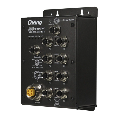
ORiNG TES-3080-M12 Series User manual
ORiNG

ORiNG TES-3080-M12 Series User manual

Popular Switch manuals by other brands

Logik L4THUB10 quick start guide

Logik

Logik L4THUB10 quick start guide

MikroTik CRS328-4C-20S-4S+RM quick start guide

MikroTik

MikroTik CRS328-4C-20S-4S+RM quick start guide

Quartz Q16 System manual

Quartz

Quartz Q16 System manual

Enterasys RoamAbout RBT-8200 installation guide

Enterasys

Enterasys RoamAbout RBT-8200 installation guide

Eaton EATS16N Installation and user manual

Eaton

Eaton EATS16N Installation and user manual

Avaya VSP 4000 4450GTX-HT-PWR+ Quick install guide

Avaya

Avaya VSP 4000 4450GTX-HT-PWR+ Quick install guide

Belkin F1DN104M user manual

Belkin

Belkin F1DN104M user manual

JDS Uniphase SB Series user manual

JDS Uniphase

JDS Uniphase SB Series user manual

Fender GTX-7 owner's manual

Fender

Fender GTX-7 owner's manual

AVCOMM 620GX4 instruction manual

AVCOMM

AVCOMM 620GX4 instruction manual

FS IES3100-8T4F-P quick start guide

FS

FS IES3100-8T4F-P quick start guide

ROSSMA IIOT-AMS Operation manual

ROSSMA

ROSSMA IIOT-AMS Operation manual

Intellinet 561099 user manual

Intellinet

Intellinet 561099 user manual

D-Link DXS-3600-16S manual

D-Link

D-Link DXS-3600-16S manual

Linksys LGS108P Frequently asked questions

Linksys

Linksys LGS108P Frequently asked questions

Compex MicroHub TP1006C Quick install guide

Compex

Compex MicroHub TP1006C Quick install guide

Moxa Technologies EDS-405A Hardware installation guide

Moxa Technologies

Moxa Technologies EDS-405A Hardware installation guide

Mellanox Technologies MSX6512-4R Hardware installation guide

Mellanox Technologies

Mellanox Technologies MSX6512-4R Hardware installation guide

manuals.online logo
manuals.online logoBrands
  • About & Mission
  • Contact us
  • Privacy Policy
  • Terms and Conditions

Copyright 2025 Manuals.Online. All Rights Reserved.