manuals.online logo
Brands
  1. Home
  2. •
  3. Brands
  4. •
  5. ORiNG
  6. •
  7. Switch
  8. •
  9. ORiNG TGPS-9168GT-M12 User manual

ORiNG TGPS-9168GT-M12 User manual

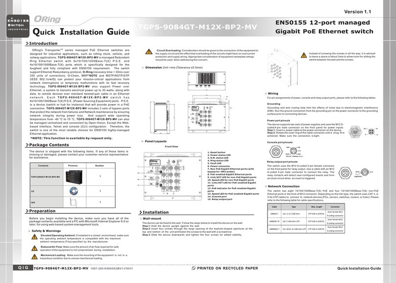
Quick Installation Guide
Version 1.0
Quick Installation Guide
Introduction
PRINTED ON RECYCLED PAPER
Q I G
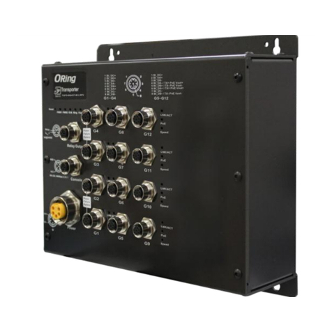
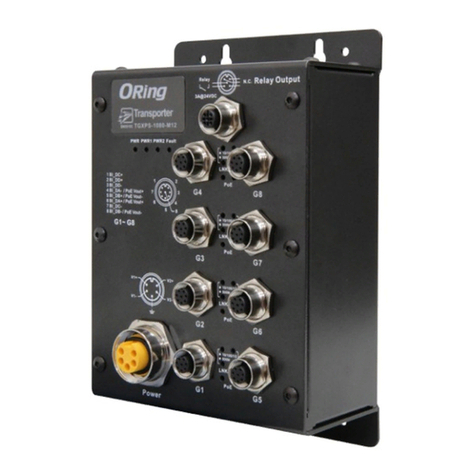
The is a managed Redundant Ring Ethernet switch withTGPS-9168GT-M12
16x10/100/1000Base-T(X) P.S.E. ports and 8x10/100/1000Base-T(X) ports.
The switch supports various Ethernet redundancy protocols such as O-Ring
(recovery time < 30ms over 250 units of connection), O-Chain and MSTP
(RSTP/STP compatible) to protect your mission-critical applications from
network interruptions or temporary malfunctions. With EN50155 compliance
and M12 connectors, the device is a perfect choice for the toughest industrial
environments as the features can ensure tight, robust connections, and
guarantee reliable operation against environmental disturbances, such as
vibration and shock. The device also supports Power-over-Ethernet which
enables electrical power (up to 15.4 watts) to be transmitted along with data
over standard twisted-pair Ethernet cables. Supporting wide operating
temperature from -40 to 75 degrees, the device can be managed centrally via
Op e n- Vis i on , t he We b- b as e d in ter fa c e, Tel n et a n d co nso le ( C LI )
configuration.
Package Contents
Installation
Wall-mount
The device can be fixed to the wall. Follow the step s bel ow to i nst all t he de vic e on th e wal l.
Step 1: Hold the evice upright against the walld
Step 2: Insert four screws through the large openin g of th e key hol e-s hap ed ap ert ure s at th e
top and bottom of the unit and fasten the screws to the wall with a screwdrive r.
Step 3: Slide the evice downwards and tighten the four screws for added s tab ili ty.d
The device is shipped with the following items. If any of these items is
missing or damaged, please contact your customer service representative
for assistance.
Preparation
Before you begin installing the device, make sure you have all of the package
contents available and a PC with Microsoft Internet Explorer 6.0 or later, for
using web-based system management tools.
Elevated Operating Ambient: If in sta lle d in a cl osed environment, make sure
the operating ambient temperature is compatib le wi th th e max imu m
ambient temperature (Tma) specified by the manufacturer.
Reduced Air F low : Make s ure t he am oun t of ai r flo w req uired for safe operation
of the equipment is not compromised during install ati on.
Mechanical Loading: Make sure the mounting of the equipment is not in a
hazardous condition due to uneven mecha nic al lo adi ng.
Circuit Overloading: Consideration should b e giv en to t he co nne cti on of t he
equipment to the supply circuit and the effect that overloading of the circuits
might have on overcurrent protection and sup ply w iri ng. Ap pro pri ate
consideration of equipment nameplat e rat ing s sho uld b e use d wh en ad dre ssi ng
this concern.
Safety & Warnings
For pin assignments of power, console and re lay o utp ut po rts , ple ase r efe r to th e fol low ing t abl es.
Cont ents
TGPS -9 168GT-M1 2
Pict ures Numbe r
1
CD 1
Dimension
Panel Layouts
Front Vie w
1. R ese t but ton
2. P owe r LED
3. R .M. s tat us LE D
4. R ing s tat us LE D
5. F aul t LED
6. C ons ole p ort
7. R ela y out put p ort
8. P owe r con nec tor
9. G iga bit E the rne t por ts
10 . PoE -en abl ed Gi gab it Et her net p ort s
11 . Lin k/A CT LE D for G iga bit p ort s
12 . Spe ed LE D for G iga bit p ort s
13 . Lin k/A CT LE D for P oE- ena ble d Gig abi t
Et her net p ort s
14 . Spe ed LE D for P oE- ena ble d Gig abi t
Et her net p ort s
15 . PoE L ED
Wiring
Grounding
Grounding and wire routing help limi t the e ffects of noise due to electromagnetic interference
(EMI). Run the ground connection from the grou ndi ng pi n on th e pow er co nne cto r to th e gro unding
surface prior to connecting devices.
Power port pinouts
The device supports two sets of power supplies a nd us es th e M23 5 -pi n
female connector on the front panel for dual power in put s.
Step 1: Insert a power cable to the power connector on the de vic e.
Step 2: Rotate the outer ring of the cable connector un til a snu g fit i s
achieved. Make sure the connection is tight.
V1+
V1-
V2+
V2-
Relay output port pinouts
Rel ay N .C.
3A@ 24 VDC
Network Connection
The device provides Ethernet ports in M12 connector type. A cco rding to the link type, the switch
uses CAT e UTP cables to connect to any other network de vic es PCs servers swi tch es3, 4, 5,5 ( , , ,
routers or hubs Please refer to the following table f or ca ble s pec ifi cat ion s., ).
TGPS-9168GT-M12
TGPS-9168GT-M12 1907-2-29-TGPS9168GTM12-1.0
S w i tc h
E N 5 0 1 5 5
I N D U S T R I A L
6
Instead of screwing the screws in all the way, it is advised to
leave a space of about 2mm to allow room for s lid ing t he
switch between the wall and the screws.
Cable
Type
Max. Length
Connector
10BASE-T Cat. 3, 4, 5 100-ohm UTP 100 m (328 ft) M12 A-coding connector
100BASE-TX Cat. 5 100-ohm UTP UTP 100 m (328 ft) M12 A-coding connector
1000BASE-T Cat. 5/Cat. 5e 100-ohm UTP UTP 100 m (328 ft) M12 A-coding conne ctor
For pin assignments of the Ethernet ports, please r efe r to th e fol low ing t abl es.
QIG 1
15
714
12
13
4
5
6
7
8
21
3
4 51 2 3
The switch uses the M12 A-coded 5-pin female c onn ect or
on the front panel for relay output. Use a cable wit h an M1 2
A-coded 5-pin male connector to connect the re lay. The
relay contacts will detect user-confi gur ed ev ent s and f orm
an close circuit when an event is triggered.
Console port pinouts
RS- 232, 96 00bps , 8, N, 1
EN50155 24-port managed
Gigabit PoE Ethernet switch
8 9 10
11
RSV D
RXD
GND
TXD
N.C .
The switch has one RS-232 (M12 5pin) consol e por t,
located on the front panel. Use a M12-to-DB9
console cable to connect the console port to your
PC's COM port.
3A@24VDC
Relay N.C.
Relay Ou tput
Consol e
RSVD
RXD
RS-232, 11520 0bps, 8 , N, 1
GND
TXD
N.C.
Power G1
LNK/ACT
Speed
G2
LNK/ACT
Speed
G3
LNK/ACT
Speed
G4
LNK/ACT
Speed
LNK/ACT
Speed
LNK/ACT
Speed
LNK/ACT
Speed
LNK/ACT
Speed
G5
G6
G7
G8
V1+
V1-
V2+
V2-
PoE
PoE
PoE
PoE
4
5
6
7
8
21
1BI_D C+
2BI_D D+
3BI_D D-
4BI_D A-
5BI_D B+
6BI_D A+
7BI_D C-
8BI_D B-
3
G1~G8
LNK/ACT
Speed
LNK/ACT
Speed
LNK/ACT
Speed
LNK/ACT
Speed
PoE
PoE
PoE
PoE
FaultRingR.M.PWR2PWR1
Reset
G9
G10
G11
G12
G13
G14
G15
G16
G17
G18
G19
G20
G21
G22
G23
G24
1BI_D C+
2BI_D D+
3BI_D D-
4BI_D A- / PoE Vou t+
5BI_D B+ / PoE Vou t-
6BI_D A+ / PoE Vou t+
7BI_D C-
8BI_D B- / PoE Vou t-
G9~G24
TGPS-91 68GT-M12
3A@24VDC
Relay N.C.
Relay O utput
Conso le
RSVD
RXD
RS-232, 115 200bp s, 8, N, 1
GND
TXD
N.C.
Power G 1
LNK/ACT
Speed
G2
LNK/ACT
Speed
G3
LNK/ACT
Speed
G4
LNK/ACT
Speed
LNK/ACT
Speed
LNK/ACT
Speed
LNK/ACT
Speed
LNK/ACT
Speed
G5
G6
G7
G8
V1+
V1-
V2+
V2-
PoE
PoE
PoE
PoE
4
5
6
7
8
21
1BI_ DC+
2BI_ DD+
3BI_ DD-
4BI_ DA-
5BI_ DB+
6BI_ DA+
7BI_ DC-
8BI_ DB-
3
G1~G8
LNK/ACT
Speed
LNK/ACT
Speed
LNK/ACT
Speed
LNK/ACT
Speed
PoE
PoE
PoE
PoE
FaultRingR.M.PWR2PWR1
Reset
G9
G10
G11
G12
G13
G14
G15
G16
G17
G18
G19
G20
G21
G22
G23
G24
1BI_ DC+
2BI_ DD+
3BI_ DD-
4BI_ DA- / P oE Vout+
5BI_ DB+ / PoE Vo ut-
6BI_ DA+ / PoE Vo ut+
7BI_ DC-
8BI_ DB- / PoE Vo ut-
G9~G2 4
TGPS-9168GT-M12
8-Pin Gigabit Non-PoE Port
Definition
PIN Definition
1 BI_DC+
2 BI_DD+
3 BI_DD-
4 BI_DA-
5 BI_DB+
6 BI_DA+
7 BI_DC-
8 BI_DB-
8-Pin Gigabit PoE Port
Definition
PIN Definition
1 BI_DC+
2 BI_DD+
3 BI_DD-
4 BI_DA- with PoE Vout+
5 BI_DB+ with PoE Vout-
6 BI_DA+ with PoE Vout+
7 BI_DC-
8 BI_DB- with PoE Vout-
Q I G Quick Installation Guide
PRINTED ON RECYCLED PAPER
Quick Installation Guide
Version 1.0
Q I G
Specifications
S w i tc h
E N 5 0 1 5 5
I N D U S T R I A L
1. Launch the Internet Explorer and type in IP address of the device. The default static
IP address is 192.168.10.1
Follow the steps below to log in and access the system:
2. Log in with default user name and password ( bot h are ).admin
3. After logging in, you should see the follow ing s cre en. F or mo re in for mat ion o n
configurations, please refer to the user man ual . For i nfo rma tio n on op era tin g the d evi ce
using ORing’s Ope n-Vision management utility, plea se go t o ORi ng we bsi te.
Resetting
To restore the device configurations back to the factory defaults, press the button for aReset
few seconds. Once the power indicator starts to flash, release t he bu tto n. Th e dev ice w ill t hen
reboot and return to factory defaults.
Configurations
Po we r
Redu nd an t In pu t Po we r Du al D C in pu ts . 48 VD C on 5 -p in M 23 c on ne ct or
21 Wa tt s (p ow er c on su mp ti on o f P.S E. is n ot i nc lu de d).
Ph ys ica l Ch ara ct er ist ic
En cl os ur e IP -3 0
Di me ns io n (W x D x H ) 320( W) x 9 1. 3( D) x 228 (H ) mm ( 12 .6 x 3.5 9 x 8. 98 i nc h. )
Wei gh t (g ) 3 11 3 g
En vi ron me nta l
-4 0 to 8 5 C ( -4 0 to 1 85 F)
o o
St or ag e Temp erat ure
5% t o 95 % No n- co nd en si ng
Op er at in g Hu mi di ty
Re gu lat or y App ro va ls
FC C Par t 15 , CI SP R (EN55022) class A, EN50155 (EN501 21 -3 -2 , EN 55 01 1, E N5 01 21 -4 )
EM I
EN 61 00 0- 4- 2 (E SD ), E N6 10 00 -4 -3 ( RS ), E N6 10 00 -4 -4 ( EF T) , EN 61 00 0- 4- 5 (S ur ge ),
EN 61 00 0- 4- 6 (C S) , EN 61 00 0- 4- 8, E N6 10 00 -4 -1 1
EM S
IE C6 00 68 -2 -2 7
Sh oc k
IE C6 00 68 -2 -3 2
IE C6 00 68 -2 -6
Vi br at io n
Fr ee Fa ll
Wa rr ant y
5 ye ar s
EN 60 95 0- 1
Sa fe ty
Fa ul t Con ta ct
Relay Rel ay o ut pu t to c ar ry c ap ac it y of 3 A at 2 4V DC o n M1 2 co nn ec to r (5 -p in M 12 A -c od in g)
Ov er lo ad C ur re nt P rotec ti on
Revers e Pol arity Pro te ct io n
Pr es en t
Pr es en t
-4 0 to 7 5 C ( -4 0 to 1 67 F)
o o
Op er at in g Tempe rature
OR in g Sw itc h Mo de l
10 /1 00 /1 00 0 Ba se-T(X ) wi th
P.S. E. Po rts i n M1 2 Au to
MD I/ MD IX
16 x M 12 c on nec to r (8 p in A -co di ng )
Ph ys ica l Po rts
Te ch nol og y
Et he rn et S ta nd ard s
IE EE 8 02 .3 f or 1 0B ase-T
IE EE 8 02 .3 u fo r 10 0Base -TX
IE EE 8 02 .3 ab f or 1 000Ba se -T
IE EE 8 02 .3 x fo r Fl ow cont ro l
IE EE 8 02 .3 ad f or L ACP (Li nk A gg re ga ti on C on tro l Pr ot oc ol )
IE EE 8 02 .1 p fo r CO S (Cl as s of S er vi ce )
IE EE 8 02 .1 Q fo r VL AN Tagg in g
IE EE 8 02 .1 d fo r ST P (Span ni ng Tree P ro to co l)
IE EE 8 02 .1 w fo r RS TP (Ra pi d Spa nn in g Tree Pr ot oc ol )
IE EE 8 02 .1 s fo r MS TP (M ul ti pl e Sp an ni ng Tr ee P ro to co l)
IE EE 8 02 .1 x fo r Au th ent ic at io n
IE EE 8 02 .1 AB f or L LDP (Li nk L ay er D is co ve ry P ro to co l)
IE EE 8 02 .3 af P oE s pe ci fi catio n
8K
MA C Tabl e
8
Pr io ri ty Q ue ue s
10 /1 00 /1 00 0B ase-T( X) p or ts
in M 12 A ut o MD I/ MD IX 8 x M1 2 co nn ect or ( 8- pi n A-c od in g)
St or e- an d- Fo rw ar d
Pr oc es si ng
Sw it ch P ro pe rt ie s
Sw it ch in g la te nc y: 7 us
Sw it ch in g ba nd wi dth: 48 G bp s
Ma x. N um be r of A va il ab le V LA Ns : 40 95
IG MP m ul ti ca st g rou ps : 12 8 fo r ea ch V LA N
Port ra te limi ti ng : Us er D ef in e
Se cu ri ty F ea tu re s
De vi ce B in di ng s ecuri ty f ea tu re
En ab le /d is ab le po rt s, M AC b as ed p or t se cu rity
Port b as ed n et wo rk a cc es s contr ol ( 80 2. 1x )
VL AN ( 80 2. 1Q ) to s egreg at e an d se cu re n et wo rk tra ffic
Radi us c en tr al iz ed p as sw or d ma nag em en t
SN MP v 1/ v2 c/ v3 e ncr yp te d au th en ti ca ti on an d ac ce ss s ec ur it y
Ht tp s / SS H en ha nc e ne tw ork s ec ur it y
So ft wa re F ea tu re s
ST P/ RS TP /M ST P (IE EE 8 02 .1 D/ w/ s)
Redu nd an t Ri ng ( O- Ri ng ) with re co ve ry t im e le ss t ha n 10 ms o ve r 25 0u nit s
Su pp or t TT DP P ro to co l (Trai n Topo lo gy Disc over y Pr ot oc ol ) to m ap t he I P addre ss a ut om at ic al ly
TOS/ Di ff se rv s up po rt ed
Qu al it y of S er vi ce ( 802 .1 p) f or r ea l- ti me t ra ff ic
VL AN ( 80 2. 1Q ) wi th VLAN t ag gi ng a nd G VR P su pp ort ed
IG MP S no op in g
IP -b as ed b an dw idt h ma na ge me nt
Ap pl ic at io n- bas ed Q oS m an ag em en t
DO S/ DD OS a ut o pr eventio n
Port c on fi gu ra ti on , st at us , st ati st ic s, m on it or in g, secu ri ty
DH CP S er ve r / Cl ie nt s up por t
SN TP, NT P fo r sy nc hr on izi ng o f cl oc ks o ve r ne tw or k
SM TP C li en t
Mo db us T CP
Ne tw or k Re du nd an cy
O- Ri ng
O- Ch ai n
MR P( *N ot e)
MS TP ( RS TP /S TP c omp at ib le )
PoE Ou tp ut Pow er
TG PS -9 16 8G T- M1 2
Up t o 9. 6K B yt es
Ju mb o fr am e
RS -2 32 S er ia l Co nsole Po rt RS -2 32 i n M1 2 (5 -p in M 12 A- co ding) connector wit h co ns ol e ca bl e. 115 20 0b ps , 8, N , 1
Powe r Co ns um pt io n( Typ .)
24 0 Wat ts
After installing the and connecting cables, he green power LEDswitch t
should turn on. Please refer to the following tablet for LED indication.
EN 5 50 22 , EN 5 50 24 (C E EM C) ,E N 50 12 1- 4, EN 6 09 45 , FC C, E N 50 12 1- 3- 2( EN 50 15 5) , EN 6 10 00 -6 -2 ,
EN 6 10 00 -6 -4 ,I EC 6 10 00 -3 -2 , IE C 61 00 0- 3- 3
EM C
IE C 60 57 1, I EC 6 22 36 -3 -2
Rail way
*N ot e: Th is fu nc tio n is a vai lab le b y req ue st on ly
TGPS-9168GT-M12
TGPS-9168GT-M12
EN50155 24-port managed
Gigabit PoE Ethernet switch
LED
Color
Status
Description
PWR1 Green On DC power module 1 activated
PWR2 Green On DC power module 2 activated
R.M Green On Device operating in Ring Master mode
Ring Green
On Ring enabled
Blinking Ring structure is broken
Fault Amber On Errors occur (i.e. power failure or port malfunctioning)
10/100/1000Base-T(X) P.S.E Ethernet ports
LNK/ACT Green On Port is linked
Blinking Transmitting data
PoE Green On Power supplied over Ethernet
Speed
Green On Port is running at 1000Mbps
Amber On Port is running at 100Mbps
Green/Amber Off Port is running at 10Mbps
10/100/1000Base-T(X) Ethernet ports
LNK/ACT Green On Port is linked
Blinking Transmitting data
Speed
Green On Port is running at 1000Mbps
Amber On Port is running at 100Mbps
Green/Amber Off Port is running at 10Mbps
ORi ng Indust rial Netw o rking Cor p.
Copyrig ht© 2017 O Ring
All right s reserved .
TEL: +886 -2- 2218-106 6
FAX: +886- 2-2 218-1014
Website: www. oringnet .com
E-mail: s upp ort@orin gnet.com

Other ORiNG Switch manuals

ORiNG IPS-1042FX-24V Series User manual

ORiNG

ORiNG IPS-1042FX-24V Series User manual

ORiNG TES-250-M12 User manual

ORiNG

ORiNG TES-250-M12 User manual

ORiNG IGS-1050A User manual

ORiNG

ORiNG IGS-1050A User manual

ORiNG TGPS-9168GT-M12-BP2-24V User manual

ORiNG

ORiNG TGPS-9168GT-M12-BP2-24V User manual

ORiNG IGS-1042GPA User manual

ORiNG

ORiNG IGS-1042GPA User manual

ORiNG IGS-3044GC User manual

ORiNG

ORiNG IGS-3044GC User manual

ORiNG TGPS-9164GT-M12X-BP2-24V User manual

ORiNG

ORiNG TGPS-9164GT-M12X-BP2-24V User manual

ORiNG TPS-3882GT-M12-BP1 User manual

ORiNG

ORiNG TPS-3882GT-M12-BP1 User manual

ORiNG IES-2050-M12 User manual

ORiNG

ORiNG IES-2050-M12 User manual

ORiNG IGS-9084GP-FB2-SS User manual

ORiNG

ORiNG IGS-9084GP-FB2-SS User manual

ORiNG IDS-342GT User manual

ORiNG

ORiNG IDS-342GT User manual

ORiNG IGPS-1411GTPA User manual

ORiNG

ORiNG IGPS-1411GTPA User manual

ORiNG IGPS-9084GP-LA User manual

ORiNG

ORiNG IGPS-9084GP-LA User manual

ORiNG IES-3240 User manual

ORiNG

ORiNG IES-3240 User manual

ORiNG TGPS-9080-M12A-MV User manual

ORiNG

ORiNG TGPS-9080-M12A-MV User manual

ORiNG RGPS-R9244GP+-P Series User manual

ORiNG

ORiNG RGPS-R9244GP+-P Series User manual

ORiNG IPS-1080-24V User manual

ORiNG

ORiNG IPS-1080-24V User manual

ORiNG GS-9164GF Series User manual

ORiNG

ORiNG GS-9164GF Series User manual

ORiNG TES-3080-M12 Series User manual

ORiNG

ORiNG TES-3080-M12 Series User manual

ORiNG DGS-9168GP-SS-AIO_S User manual

ORiNG

ORiNG DGS-9168GP-SS-AIO_S User manual

ORiNG IES-1050A User manual

ORiNG

ORiNG IES-1050A User manual

ORiNG IGS-1082GP User manual

ORiNG

ORiNG IGS-1082GP User manual

ORiNG IGS-9084GP User manual

ORiNG

ORiNG IGS-9084GP User manual

ORiNG IGS-9848GPF User manual

ORiNG

ORiNG IGS-9848GPF User manual

Popular Switch manuals by other brands

HP ProCurve 2610 Series Read me first

HP

HP ProCurve 2610 Series Read me first

CALEFFI 626 Series manual

CALEFFI

CALEFFI 626 Series manual

PDL POWERGUARD 956 SHORT INSTALLATION OPERATING INSTRUCTIONS

PDL

PDL POWERGUARD 956 SHORT INSTALLATION OPERATING INSTRUCTIONS

Sitecom CN-5001 user manual

Sitecom

Sitecom CN-5001 user manual

PCB Piezotronics IMI SENSORS 691B44 Series Installation and operating manual

PCB Piezotronics

PCB Piezotronics IMI SENSORS 691B44 Series Installation and operating manual

4O3A Antenna Genius quick start guide

4O3A

4O3A Antenna Genius quick start guide

LEGRAND LIMOGES Cedex 87045 quick start guide

LEGRAND

LEGRAND LIMOGES Cedex 87045 quick start guide

ZyXEL Communications XGS-4526 user guide

ZyXEL Communications

ZyXEL Communications XGS-4526 user guide

Niveo Professional NGSME16T2H-AV user manual

Niveo Professional

Niveo Professional NGSME16T2H-AV user manual

Philips hue user manual

Philips

Philips hue user manual

ADDER AdderView Pro 8 DVI user guide

ADDER

ADDER AdderView Pro 8 DVI user guide

Larson Electronics EPS-PB10-MS-AT-V4 manual

Larson Electronics

Larson Electronics EPS-PB10-MS-AT-V4 manual

Ruijie RG-S6150-X Series Hardware  installation and reference guide

Ruijie

Ruijie RG-S6150-X Series Hardware installation and reference guide

GTV AE-WDBP1-10 manual

GTV

GTV AE-WDBP1-10 manual

Pickering 40-202 user manual

Pickering

Pickering 40-202 user manual

HP ProCurve 3500-48 Product End-of-Life Disassembly Instructions

HP

HP ProCurve 3500-48 Product End-of-Life Disassembly Instructions

SUCO 0340 Series operating instructions

SUCO

SUCO 0340 Series operating instructions

Lucent Technologies OptiStar EdgeSwitch User's operation guide
Lucent Technologies

Lucent Technologies OptiStar EdgeSwitch User's operation guide
manuals.online logo
manuals.online logoBrands
  • About & Mission
  • Contact us
  • Privacy Policy
  • Terms and Conditions

Copyright 2025 Manuals.Online. All Rights Reserved.