manuals.online logo
Brands
  1. Home
  2. •
  3. Brands
  4. •
  5. ORiNG
  6. •
  7. Switch
  8. •
  9. ORiNG IPS-3082GC-24V User manual

ORiNG IPS-3082GC-24V User manual

G2
P1
P3
P5
P1
P3
P2
P4
P6
P8P7
G1
G1 LIN K / ACTG2
PWR
PWR 1
PWR 2
IPS-3082GC
7
5 6
8
P.O.E .
3
1 2
4
Quick Installation Guide
Introduction
PRINTED ON RECYCLED PAPER
is managed redundant ring Ethernet switch with 8x10/100Base-T(X)IPS-3082GC-24V
ports with 15.4Watts PoE (P.S.E.) function and 2xGigabit combo ports. With completely
support of Ethernet redundancy protocol, O-Ring (recovery time < 10/30ms over 250
units of connection), O-Chain, MRP and MSTP/RSTP/STP (IEEE 802.1s/w/D)*NOTE
can protect your mission-critical applications from network interruptions or temporary
malfunctions with its fast recovery technology. Another O-Chain is the revolutionary
network redundancy technology that provides the add-on network redundancy topology
for any backbone network, O-Chain allows multiple redundant network rings of different
redundancy protocols to join and function together as a larger and more robust
compound network topology. O-Chain providing ease-of-use while maximizing fault-
recovery swiftness, flexibility, compatibility, and cost-effectiveness in one set of network
redundancy topology. also supports Power over Ethernet, a systemIPS-3082GC-24V
to transmit electrical power, along with data, to remote devices over standard twisted-
pair cable in an Ethernet network. Each switch had 8X10/100Base-IPS-3082GC-24V
T(X) 15.4Watts P.S.E. (Power Sourcing Equipment) ports. P.S.E. is a device (switch or
hub for instance) that will provide power in a PoE setup. supportsIPS-3082GC-24V
DDM (Digital Diagnostic Monitoring) function, which can monitor instantly the status of
electronic voltage, current and temperature. All function of can beIPS-3082GC-24V
managed centralized by a powerful windows utility — Open-Vision. In addition, the wide
operating temperature range from -40 to 70 C can satisfy most of operating
o
environment. Therefore, these switches are one of the most reliable choice for highly-
managed and Fiber Ethernet application with PoE function.
Preparation
Before you begin installing the switch, make sure you have all of the package
contents available and a PC with Microsoft Internet Explorer 6.0 or later, for
using web-based system management tools.
Elevated Operating Ambient: If installed in a closed or multi-unit rack
assembly, the operating ambient temperature of the rack environment may be
greater than room ambient. Therefore, consideration should be given to
installing the equipment in an environment compatible with the maximum
ambient temperature (Tma) specified by the manufacturer.
Safety & Warnings
Dimension
Panel Layouts
1. Power LED
2. PWR1 LED
3. PWR2 LED
4. R.M. status LED
5. Ring status LED
6. Faulty relay indicator
7. Console port
8. Link/Act LED for Gigabit port
9. 100Mbps indicator for Gigabit port
10. Combo ports
11. Link/Act LED for SFP ports
12. Link/Act LED for Ethernet port
13. Duplex/Collision indicator
14. LAN ports
15. Reset button
16. PoE LED for LAN port
Package Contents
The device is shipped with the following items. If any of these items is
missing or damaged, please contact your customer service representative for
assistance.
7
1
2
3
4
5
6
1. Terminal blocks: PWR1,
PWR2 (24 36V DC), Relay-
2. Ground wire.
Installation
Step 1: Slant the switch and screw the Din-rail kit onto the back of the switch, right in
the middle of the back panel.
Step 2: Slide the switch onto a DIN-rail from the Din-rail kit and make sure the switch
clicks into the rail firmly.
DIN-rail Installation
Step 1: Screw the two pieces of wall-mount kits onto both ends of the rear panel of the
switch. A total of six screws are required, as shown below.
Step 2: Use the switch, with wall mount plates attached, as a guide to mark the
correct locations of the four screws.
Step 3: Insert a screw head through the large parts of the keyhole-shaped apertures,
and then slide the switch downwards. Tighten the screws for added stability.
Wall-mounting
Q I G IPS-3082GC-24V 1907-200-P3082GC242-FX011
Reduced Air Flow: Installation of the equipment in a rack should be such that the
amount of air flow required for safe operation of the equipment is not
compromised.
Mechanical Loading: Mounting of the equipment in the rack should be such that
a hazardous condition is not achieved due to uneven mechanical loading.
Circuit Overloading: Consideration should be given to the connection of the equipment
to the supply circuit and the effect that overloading of the circuits might have on
overcurrent protection and supply wiring. Appropriate consideration of equipment
nameplate ratings should be used when addressing this concern.
Network Connection
The switch provides standard Ethernet ports. According to the link type, the switch uses
CAT 3,4,5,5e UTP cables to connect to any other network devices (PCs, servers,
switches, routers, or hubs). Please refer to the following table for cable
specifications.
Cable Types and Specifications:
Cable Type Max. Length Connector
10BASE-T Cat. 3, 4, 5 100-ohm UTP 100 m (328 ft) RJ-45
100BASE-TX Cat. 5 100-ohm UTP UTP 100 m (328 ft) RJ-45
1000BASE-T Cat. 5 / Cat. 5e 100-ohm UTP UTP 100 m (328 ft) RJ-45
14
12
13
IPS-3082GC-24V
Version 2.1
Unit =mm (Tolerance ±0.5mm)
*NOTE : This function is available by request only.
15
The product is open type, intended to be installed in and industrial control panel or an enclosure.
!
Warnin g [ AVERTISSEMENT]
Take into consideration the following guidelines before wiring the device
[Tenez compte des directrices suivantes avant de câbler l’appareil.]
1. Terminal block is mating with Plug and suitable for 12-24AWG.
Torque value 4.5 lb-in.
[Le bornier est compat ible avec les connecteurs et convient pour 12-24AWG.
Valeur de couple 4,5 lb-in.]
2. The temperature rating of the input connection cable should higher than 105° C
[La température de service nominale du câble d’entrée doit être supérieure à 105 °C]
3. Use Copper Conductors O nly.
[Utilisez uniquemen t des conducteurs en cuivre.]
* Indoor use and pollut ion degree II, it must be wiped with a dry cloth for clean up the
device and label.
* Utilisation en int érieur et degré de pollution II, il faut l'essuyer avec un chiffon sec
pour nettoyer l'appareil et son étiquette.
* Do not block air ventilation holes.
* Ne bouchez pas les ori fices de ventilation.
* If the equipment is used in a manner not specified by the manufacturer, the
protection provided by the equipment may be impaired.”
* Si l’appareil es t utilise d’une maniere non specifiee par le fabricant, la protection
qu’il apporte peut se voir diminuee.”
* Shall be mounted in the Industrial Control Panel and ambient temperature is not
exce ed 75 degree C
* doit être monté dans le panneau de commande industriel et la température ambiante
ne doit pas dépasser 75 degrés C
Contents
DIN-rail Kit
CD
IPS-3082GC-24V
Pictures Number
X 1
X 1
X 1
QIG
Console Cable
X 2
X 1
X 1
Wall-mount Kit
66.0
50.0
26.0
43.043.0 43.0
116. 0
40.0
18.0
107.5
153.6
74.3
8.0
80.5
G2
P1
P3
P5
P1
P3
P2
P4
P6
P8P7
G1
G1 LINK / A CTG2
PWR
PWR1
PWR2
Front View Rear View
1. Din-rail screw holes
2. Wall-mount screw holes
1
2
2
Bottom View
1
2
8
10
9
11
PWR -1PWR -2
1A@ 24V
DC1 2-4 8V
V2- V 2+ V1- V 1+
Fau lt
Industrial PoE Managed Ethernet
Switch
Industrial PoE Managed Ethernet
Switch
S W I T C H
I N D U S T R I A L
P o E
IPS-3082GC
7
5 6
8
P.O.E.
3
1 2
4
16
G2
P1
P3
P5
P1
P3
P2
P4
P6
P8P7
G1
G1 LINK / A CTG2
PWR
PWR1
PWR2
IPS-3082GC
7
5 6
8
P.O.E.
3
1 2
4
Q I G Quick Installation Guide
PRINTED ON RECYCLED PAPER
Version 2.1
Quick Installation Guide
Resetting
To reboot the switch, press the button less than 5 seconds.Reset
To restore the switch configurations back to the factory defaults, press the button more than 5Reset
seconds.
Specifications
Configurations
After installing the switch, the green power LED should turn on. Please refer to
the following tablet for LED indication.
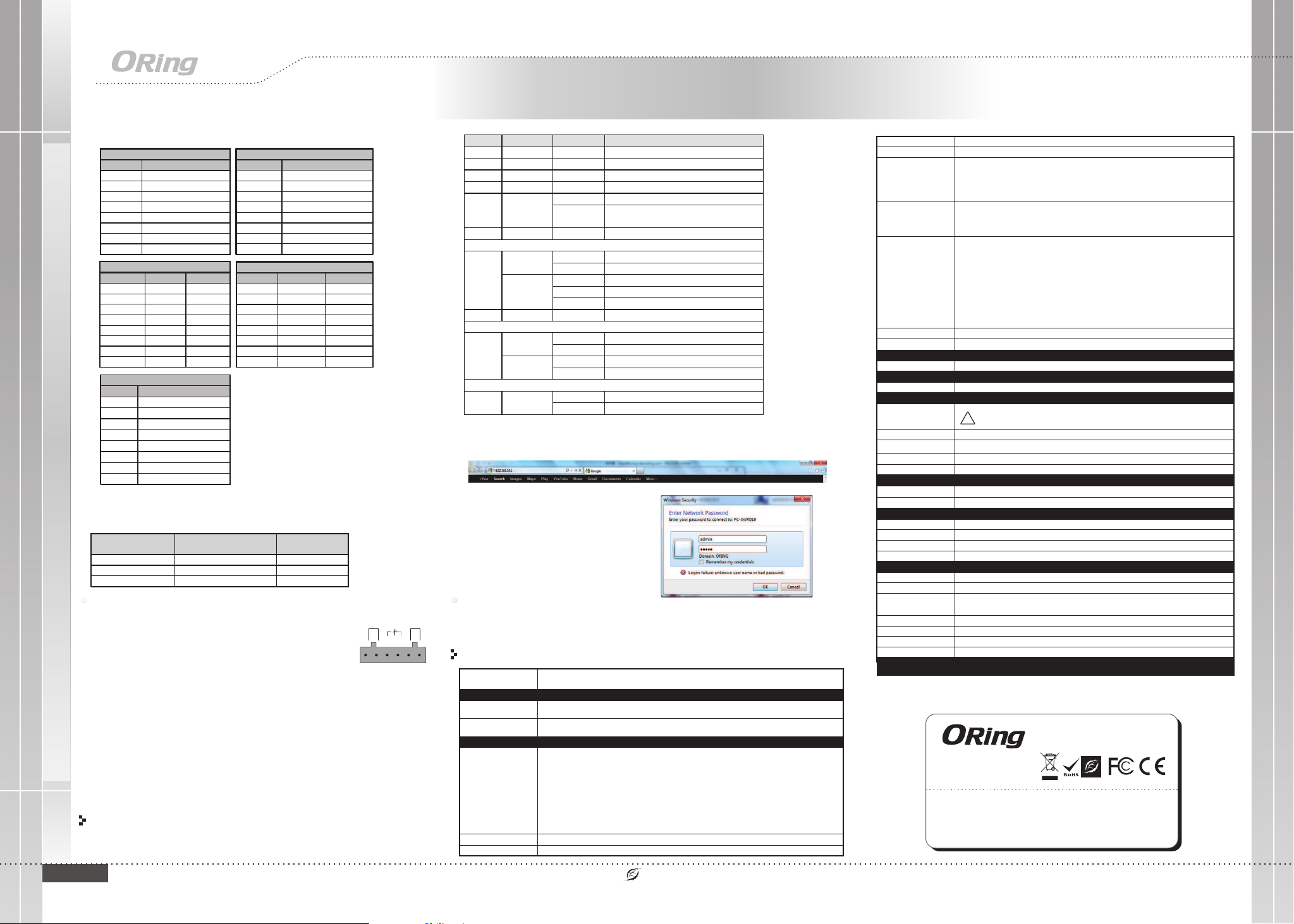
1. Launch the Internet Explorer and type in IP address of the switch. The default static IP address is
192.168.10.1
2. Log in with default user name and password
(both are ). After logging in, you shouldadmin
see the following screen. For more information
on configurations, please refer to the user
manual. For information on operating the switch
using ORing’s Open-Vision management utility,
please go to ORing website.
Follow the steps to set up the switch:
LED
Color
Status
Description
PWR Green On DC power on
PWR1 Green On DC power module 1 activated
PWR2 Green On DC power module 2 activated
R.M Green On Ring Master
Ring Green
On Ring enabled
Blinking
Ring structure is broken (i.e. part of the ring is
disconnected)
Fault Amber On Faulty relay (power failure or port disconnected)
10/100Base-T(X) Poe Ethernet ports
LNK/ACT &
Duplex
Green
On Port link up
Blinking Data transmitted
Amber
On Full-duplex mode
Blinking Half-duplex and collision occurred
Off Half-duplex mode
PoE Green On Power supplied over Ethernet
10/100/1000Base-T(X) Ethernet ports (Combo port)
LNK/ACT
with speed
Green
On Port link up
Blinking Data transmitted
Amber
On Port link at 100Mbps
Off Port link at 10/1000Mbps
SFP (Combo port)
LNK/ACT Green
On Port link up
Blinking Data transmitted
For pin assignments for different types of cables, please refer to the following tables.
10/100 Base-T(X) MDI/MDI-X
Pin Number MDI port MDI-X port
1 TD+(transmit) RD+(receive)
2 TD-(transmit) RD-(receive)
3 RD+(receive) TD+(transmit)
4 Not used Not used
5 Not used Not used
6 RD-(receive) TD-(transmit)
7 Not used Not used
8 Not used Not used
Note: “+” and “-” signs represent the
polarity of the wires that make up
each wire pair.
To connect the console port to an external management device, you need an RJ-45 to
DB-9 cable, which is also supplied in the package. Below is the console port pin
assignment information.
Console Port Pin Definition
PC (male) pin assignment RS-232 with DB9 (female) pin
assignment (RJ45-DB9 cable) RJ45 pin assignment
PIN#2 RxD PIN#2 RxD PIN#2 RxD
PIN#3 TxD PIN#3 TxD PIN#3 TxD
PIN#5 GND PIN#5 GND PIN#5 GND
Wiring
The switch supports dual redundant power supplies, Power Supply1
(PWR1) and Power Supply 2 (PWR2). The connections for PWR1,
PWR2 and the RELAY are located on the terminal block.
STEP 1: Insert the negative/positive wires into the V-/V+ terminals,
respectively.
STEP 2: To keep the DC wires from pulling loose, use a small flat-
blade screwdriver to tighten the wire-clamp screws on the front of the
terminal block connector.
PWR-1PWR-2
1A@24 V
V2- V2+ V1- V1+
Fault
Power inputs
The two sets of relay contacts of the 6-pin terminal block connector are used to detect user-
configured events. The two wires attached to the fault contacts form an open circuit when a
user-configured when an event is triggered. If a user-configured event does not occur, the
fault circuit remains closed.
Relay contact
1000Base-T MDI/MDI-X
Pin Number MDI port MDI-X port
1 BI_DA+ BI_DB+
2 BI_DA- BI_DB-
3 BI_DB+ BI_DA+
4 BI_DC+ BI_DD+
5 BI_DC- BI_DD-
6 BI_DB- BI_DA-
7 BI_DD+ BI_DC+
8 BI_DD- BI_DC-
1000Base-T RJ-45 Port
Pin Number Assignment
1 BI_DA+
2 BI_DA-
3 BI_DB+
4 BI_DC+
5 BI_DC-
6 BI_DB-
7 BI_DD+
8 BI_DD-
10/100 Base-T(X) RJ-45 Port
Pin Number Assignments
1 TD+
2 TD-
3 RD+
4 Not used
5 Not used
6 RD-
7 Not used
8 Not used
Grounding and wire routing help limit the effects of noise due to electromagnetic
interference (EMI). Run the ground connection from the ground screws to the grounding
surface prior to connecting devices.
Grounding
OR i ng Swit ch Model
Ph y sical P orts
Te c hnolo gy
Et hern et Sta ndar ds
10 /100 B ase-T (X) Ports in RJ4 5
Au to MDI /MDI X
RS -232 S eria l Cons ole Port
Gi gabit c ombo Port in R J-45
an d SFP
Sw itch Properti es
Se curi ty Fe atures
En able /dis able p orts , MAC based p ort se curi ty
Port ba sed ne twor k acce ss control (802 .1x)
VL AN (80 2.1Q ) to seg rega te and secu re net work t raf fic
Su ppor ts Q-i n-Q VL AN for p erforma nce & se curi ty to ex pand t he VLAN spa ce
Radiu s cent ral ized p assw ord ma nagement
SN MP V1/ V2c/ V3 enc rypt ed authen tica tion a nd acc ess se curi ty
So ftwa re Featu res
ST P/RS TP/M STP (I EEE 80 2.1D /w/s )
Redun dant R ing (O -Rin g) wit h recover y time less than 10 /30m s ove r 250 un its
Fast E ther net po rts su pports le ss 10 mi llis econ ds rec ove ry tim e.NO TE 1.
. Gi gabi t Ethe rnet p orts s upports less 30 m illi seco nds re covery ti me.NO TE 2
TOS/D iffs erv su ppor ted
Qu alit y of Ser vice (802 .1p) f or rea l-ti me traffi c
VL AN (80 2.1Q ) with V LAN ta gging and G VRP su ppor ted
IG MP Sno opin g for mu ltic ast filte ring
Port co nfig ura tion , stat us, st atis tics, mon itor ing, s ecur ity
SN TP for s ynch roni zing o f clocks ov er net work
Su ppor t PTP Cl ient ( Prec ision Tim e Prot ocol ) cloc k sync hron izat ion
DH CP Ser ver / Clien t supp ort
Port Trunk su ppor t
MV R (Mul tica st VLA N Reg istrati on) su pport
Mo dbus TCP
Ne twor k Red unda ncy O- Ring , O-Ch ain, M RP , MS TP/R STP/ STP*N OTE
RS -232 i n RJ45 c onne ctor w ith conso le cab le. 96 00bp s, 8, N, 1
IP S -3082 GC-24V
8
2
IE EE 802 .3 for 1 0Bas e-T
IE EE 802 .3u fo r 100B ase-TX and 1 00Ba se-F X
IE EE 802 .3z fo r 1000 Base -X
IE EE 802 .3ab f or 100 0Bas e-T
IE EE 802 .3x fo r Flow c ontr ol
IE EE 802 .3ad f or LAC P (Lin k Aggrega tion C ontr ol Pro toco l)
IE EE 802 .1D fo r STP (S pann ing Tree Pr otoc ol)
IE EE 802 .1p fo r COS (C lass o f Service )
IE EE 802 .1Q fo r VLAN Tagg ing
IE EE 802 .1w fo r RSTP ( Rap id Spa nnin g Tre e Prot ocol )
IE EE 802 .1s fo r MSTP ( Mult iple Span ning Tree Pr otoc ol)
IE EE 802 .1x fo r Authenticat ion
IE EE 802 .1AB f or LLD P (Link Lay er Discov ery Pr otoc ol)
IE EE 802 .3af PoE sp ecif ication ( up to 15 .4 Watts p er por t for P.S.E.)
Sw itch ing laten cy: <7 u s
Sw itch ing bandw idth : 7.2G bps
Th roug hput ( packet pe r seco nd): 4 .166 Mpps @64B ytes p acket
Ma x. Num ber of Ava ilab le VLANs: 4096
VL AN ID Range : VID 1 to 4 095
IG MP mul tica st gro ups: 1 024
Port rate li miti ng: Us er Def ine
MA C Tab le 8K
Pr oces sing S tore -an d-Forwa rd
Packet buffer 1Mbit s
En v ironm ental
-4 0 to 85 C (-40 to 185 F )
o o
St ora ge Tem peratur e
Op era ting Temperat ure
5% t o 95% No n-co nden singOp era ting H umid ity
Reg ulato ry appro vals
EN 5 5032 , CISP R32, E N 6100 0-3-2, EN 6 1000 -3-3 , FCC Part 15 B c lass AEM I
EN 5 5024 ( IEC/ EN 610 00-4 -2 (ES D: Contac t 4KV, Air 8 KV), I EC/E N 6100 0-4- 3 (RS: 3 V),
IE C/EN 6 1000 -4-4 ( EFT Power 1 KV, Sign al 0.5 KV), I EC/E N 61000-4-5 (Su rge: Powe r 2KV, RJ4 5 1KV) ,
IE C/EN 6 1000 -4-6 ( CS: 3V ), IEC /EN 61000 -4-8 (PFM F), IE C/EN 6 1000 -4-1 1 (DIP ))
EM S
IE C600 68-2 -27Sh ock
IE C600 68-2 -31
IE C600 68-2 -6Vi bra tion
EN 6 0950 -1, UL 6 0950 -1, IE C 60950-1
Sa fety
Fr ee Fall
MT B F
37 5,56 4 hrs
-4 0 to 70 C (-40 to 167 F )
o o
Fau lt cont act
Relay Relay out put to c arry c apac ity of 1A at 24 V DC
Po wer
Redun dant I nput p ower
Power c onsu mpti on(Typ. ) <1 2Watts , 24VD C/0. 5A, 36VDC /0.3 3A (po wer co nsum ptio n of P.S. E. is no t incl uded )
Ov erlo ad curren t prot ecti on
Rever se polari ty pro tect ion
Pr esen t
No t Pres ente d
Ph y sical C haract eristi c
Di mens ion (W x D x H )
Weig ht (g) 12 60 g
Du al DC in puts , 24~3 6VDC on 6-pin ter mina l bloc k
* UL 6 1010 -1 or 61 010- 2-201 power sup ply on ly.Su ppli ed by SE LV or dou ble in sula tion s ourc e eva luat ed by
* Fourn i par la s ourc e SELV l' alim enta tion U L 61010-1 orou d oubl e isol atio n éva luée u niqueme nt par
61 010- 2-20 1.
74 .3 (W) x 1 07.5 ( D) x 153 .6 (H)mm (2 .93 x 4. 23 x 6.0 5 inch .)
Pr iori ty Que ues 4
Re s et Func tion
Reset B utto n < 5 se c: Sy stem r eboo t, > 5 sec : Fa ctor y default
CE E MC (EN 5 5024 , EN 550 32), F CC Part 15 BEM C
Wa r ranty
*NOTE : This function is available by request only
!
Up t o 2000 mOp era ting A ltti tude
ORing Industrial Networking Corp.
Copyright© 2012 ORing
All rights reserved.
TEL: +886-2-2218-1066
FAX: +886-2-2218-1014
Address 3F No 542 2 Zhongzheng Rd Xindian Dist New: ., . - , ., .,
Taipei City 23148 Taiwan,
Website: www.oringnet.com
E-mail: support@oringnet.com
Contact for maintenance and repair service:
5 ye ars
10/100Base-T(X) P.S.E. RJ-45 port
Pin No.
Description
#1
TD+ with PoE Power Input +
#2
TD- with PoE Power Input +
#3
RD+ with PoE Power Input -
#4
N.C.
#5
N.C.
#6
RD- with PoE Power Input -
#7
N.C.
#8
N.C.
PoE Total Power B udge t <24 VDC@60 Watt s Max.
>2 4VDC @120 Wat ts Max .
IPS-3082GC-24V
IPS-3082GC-24V Industrial PoE Managed Ethernet
Switch

Other ORiNG Switch manuals

ORiNG TRGPS-9084GT-M12X-BP2-MV User manual

ORiNG

ORiNG TRGPS-9084GT-M12X-BP2-MV User manual

ORiNG TGPS-9084GT-M12 User manual

ORiNG

ORiNG TGPS-9084GT-M12 User manual

ORiNG IGS-9848GPF User manual

ORiNG

ORiNG IGS-9848GPF User manual

ORiNG RGS-7244GP User manual

ORiNG

ORiNG RGS-7244GP User manual

ORiNG IES-3162GC Series User manual

ORiNG

ORiNG IES-3162GC Series User manual

ORiNG IES-2050 User manual

ORiNG

ORiNG IES-2050 User manual

ORiNG IPS-2042 Series User manual

ORiNG

ORiNG IPS-2042 Series User manual

ORiNG IES-2050-M12 User manual

ORiNG

ORiNG IES-2050-M12 User manual

ORiNG IGS-9122GPM User manual

ORiNG

ORiNG IGS-9122GPM User manual

ORiNG IES-3240 User manual

ORiNG

ORiNG IES-3240 User manual

ORiNG IES-1041FX-MM-SC User manual

ORiNG

ORiNG IES-1041FX-MM-SC User manual

ORiNG TPS-3882GT-M12-BP1 User manual

ORiNG

ORiNG TPS-3882GT-M12-BP1 User manual

ORiNG EN50155 User manual

ORiNG

ORiNG EN50155 User manual

ORiNG IPS-1042FX-24V Series User manual

ORiNG

ORiNG IPS-1042FX-24V Series User manual

ORiNG IES-1080A User manual

ORiNG

ORiNG IES-1080A User manual

ORiNG Transporter Series User manual

ORiNG

ORiNG Transporter Series User manual

ORiNG TXPS-1080-M12-24V Series User manual

ORiNG

ORiNG TXPS-1080-M12-24V Series User manual

ORiNG IGPS-1042GPA User manual

ORiNG

ORiNG IGPS-1042GPA User manual

ORiNG IGS-9084GP-FB2 User manual

ORiNG

ORiNG IGS-9084GP-FB2 User manual

ORiNG IGPS-9084GP User manual

ORiNG

ORiNG IGPS-9084GP User manual

ORiNG IGS-9084GP User manual

ORiNG

ORiNG IGS-9084GP User manual

ORiNG TRGPS-9084TG-M12X-BP2-MV User manual

ORiNG

ORiNG TRGPS-9084TG-M12X-BP2-MV User manual

ORiNG RES-1242P User manual

ORiNG

ORiNG RES-1242P User manual

ORiNG RGS-9244GP User manual

ORiNG

ORiNG RGS-9244GP User manual

Popular Switch manuals by other brands

CoolGear USBG-4U2ML installation guide

CoolGear

CoolGear USBG-4U2ML installation guide

AirLive POE-FSH808AT user manual

AirLive

AirLive POE-FSH808AT user manual

AirLive POE-GSH1602M-200 Quick setup guide

AirLive

AirLive POE-GSH1602M-200 Quick setup guide

Black Box SW281A-R2 Specifications

Black Box

Black Box SW281A-R2 Specifications

Black Box MODULAR SMART SWITCH SW925AE user manual

Black Box

Black Box MODULAR SMART SWITCH SW925AE user manual

Alcatel-Lucent 7210 SAS-T installation guide

Alcatel-Lucent

Alcatel-Lucent 7210 SAS-T installation guide

Green Brook t205-c Operating	 instruction

Green Brook

Green Brook t205-c Operating instruction

ExtremeSwitching 3600 Series Troubleshooting

ExtremeSwitching

ExtremeSwitching 3600 Series Troubleshooting

Tripp Lite B321-4X1-HDVC owner's manual

Tripp Lite

Tripp Lite B321-4X1-HDVC owner's manual

Planet VC24024 Quick installaion guide

Planet

Planet VC24024 Quick installaion guide

3One data IPS7110 Series Quick installation guide

3One data

3One data IPS7110 Series Quick installation guide

digi-tech AC-1706 user manual

digi-tech

digi-tech AC-1706 user manual

Atos E-DAP-2 Series manual

Atos

Atos E-DAP-2 Series manual

SMART-AVI SM-DVN-4Q quick start guide

SMART-AVI

SMART-AVI SM-DVN-4Q quick start guide

Good Way USB 2-to-2 user manual

Good Way

Good Way USB 2-to-2 user manual

Black Box 12 VDC load user manual

Black Box

Black Box 12 VDC load user manual

Planet POE-151 user manual

Planet

Planet POE-151 user manual

BZB Gear BG-PSC11X2-HDBT user manual

BZB Gear

BZB Gear BG-PSC11X2-HDBT user manual

manuals.online logo
manuals.online logoBrands
  • About & Mission
  • Contact us
  • Privacy Policy
  • Terms and Conditions

Copyright 2025 Manuals.Online. All Rights Reserved.