manuals.online logo
Brands
  1. Home
  2. •
  3. Brands
  4. •
  5. ParaBody
  6. •
  7. Fitness Equipment
  8. •
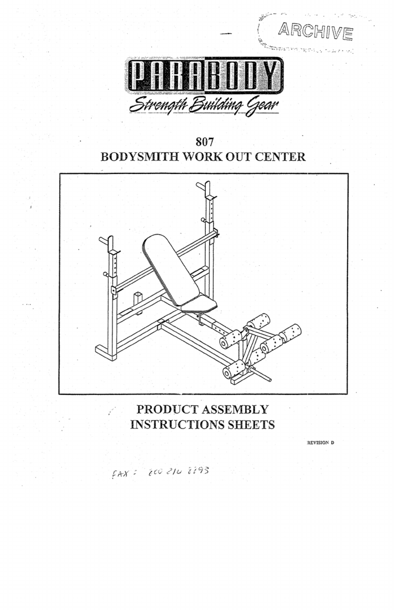
  9. ParaBody 704101 Mounting instructions

ParaBody 704101 Mounting instructions

704101
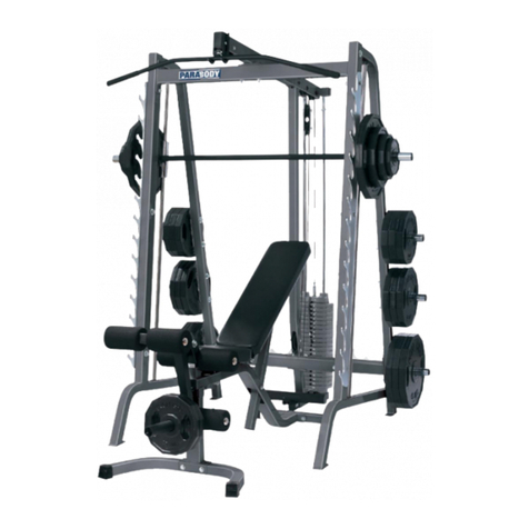
REGGIE WHITE ALL PRO SYSTEM
PRODUCT ASSEMBLY
INSTRUCTIONS SHEETS
1
I l/21195
704101 REGGIE WHITE ALL PRO SYSTEM ASSEMBLY PARTS LIST
SORT ANDCOUNTALL PARTS BEFOREBEGINNINGASSEMBLY
~Qr¥
ITEM NAME/DESCRIPTION !
I. 3/8X6IN.BOLT....................................................................................................................
2. 3/8X3-I/4IN.BOLT............................................................ . .................................... 3
3. 3/8X3IN.BOLT.................................................................. ".......19
4. 3/8X2-3/4IN.BOLT........................................................................................................... 4
5. 3/8X2-I~2INBOLT............................................................................................................. 6
6. 3/8X2IN.BOLT................................................................................................................... I
7. 3/8XI-3/4IN.BOLT............................................................................................................. 4
3/8X1-1/2IN.BOLT............................................................................................................. 24
8.
10.
3/8[N~LOWHEIGHTLOCKNUT............................................................. ~.........................~8
II.
12. 3/8IN.SPACER................................................................... . ........
13. 1/2IN.FLANGEBEA~NG................................................ ~[~[~~]’" .........
14. SEMBLY.........................................................................
GPiNAS............................ .2
15. SPRIN , , . ........................................
16. QUICKLINK.................................... . .................................................
~7. s~HOO~..................................................................
...........
~8. C~A~..................................................................................................
L-PIN.................................................................................. . ..................................... 2
~o. ac~e......................
~INS COVE............................... .. 4
21. - ¯ Q" . ..........................................
22. 2IN.SQ.ENDCAP..................................................................
23. I-3/4INSQ.ENDCAP........................................................................................................ 4
24. I XSING~P..................................................................................................................... 2
25. CARRIAGEGUIDE............................................................................................................. 4
....................................................................................................
...................................................................................................
27.
28 PARAGLIDEST~P............................................................................................................ 4
29. MUSHROOMCAP................................................................................................................. 2
30. 3/4IN.SQ.RUBBERBUMPER...........................................................................................
NOTE: BOLT LENGTH IS MEASUREDFROM THE UNDERSIDE OF THE HEAD OF THE BOLT.
-- BOLTLENGTH
BOLT LENGTHRULER:
¯ 4 s ’-~--~6
123l_l ¯
2
11/21/95
704101 REGGIE WHITE ALL PRO SYSTEM ASSEMBLY PARTS LIST
SORT AND COUNT ALL PARTS BEFORE BEGINNING ASSEMBLY
_WELDMENTS/PARTS’- QTY
ITEM NAME/DESCRIPTION
UPRIGHTFRAMEWLDMT......................................... (6536202)....................................... 1
I. PULLEYMOU,~,TFLAT............................................... (6546902)....................................... 2
2. ’_’.._ (6547002).......................................
UPRIGHTWLDMI........................................................ .~ "
3. B,-,sE..................................................
(654750-).......................................
4. BAR~~~’I~~’~{"~~’I~~i"~................................................ (6~47602.~).......................................
5.
6. SAFEqI’-YRAILWLDMT................................................ (6~4780-).......................................
....... (6548002) .......................................
7. CARRIAGEWLDMT............................................ . ...... 2 ....
8. BEARINGHOUSINGWLDMT.................................... tt~4a~u) .........................
9. LEFT ARIVl WLDMT ................. (6548502)........................................
10. RIGFITARM’WLDMT................................................... (6548402).......................................
I I. PULLEYBRACKETWLDMT...................................... (6516502)........................................
12. LATBARWLDMT........................................................ (6275302).......................................
13. LOWP~OWBARWLDMT....................................... (6274402).......................................
14. LEGPEDESTALWLDMT............................................ (6549202).......................................
15. FRONTLEGWLDMT................................................... (6549502).......................................
BENCHTOPW’LDMT................................................... (6549902).......................................
16. ADJP-XDSUPPORTRIGHT........................................ (6550202).......................................
17. ADJ.PADSUPPORTLEFT........................................... (6550102)...................................
18.
19. REAR LEG W’LDMT........................ (6550502)........................................
20. ROLLERPADSWIVELWLDMT................................ (6549802).......................................
2l. HORIZONTALSUPPORT............................................. (6547202).......................................
22. CON.~ECTORPLATE................................................... (6542402).......................................
23. ROLLERPADSHAFT................................................... (6485301).......................................
24. 3-3,"16iN.ROLLERPAD............................................... (6016401)....................................... 4
25. 4X12ROLLERPAD..................................................... (6176201)....................................... 2
SMALLBACKPAD...................................................... (6550901).......................................
26. LARGEBACKPAD....................................................... (6545401)....................................... 1
27. T PAD . ............................ (6545601)....................................... I
28. SEA ......... _-.............................. (3116201)..................................... I1
29. 3-I/2IN.PULLEY..........................................................
LABEL(1-25).................. ~;.............................................(6189501).........................................
30. CABLEASSEMBLY,110............................................ (6553101).......................................
31.
32. CABLEASSEMBLY,77-5/8"........................................ (6535601)....................................... 1
3
11/21/95
704101 REGGIE WHITE ALL PRO SYSTEM ASSEMBLYINSTRUCTIONS
THANK YOU
FOR PURCHASINGTHE 7114101 REGGIE WHITEALL PRO SYSTEM~ PLEASE SAVE THESE
ASSEMBLY INSTRUCTIONS FOR YOUR PERSONAL REFERENCE, AND ADDITIONAL SERVICE
INFORMATION.
***IMPORTANT***.
THE 7~0410I REGGIE WHITEALL PROSYSTEM MUST BE ASSEMBLEDON A FLAT, LEVEL
SUR(ACE TO ASSURE ITS PROPER FUNCTION.
PARABODY STRONGLY RECOMMENDSTHAT THIS PRODUCT BE ASSEMBLED BY TWO
PEOPLE TO AVOID POSSIBLE INJURY.
KEEPALLFRAY.CONNECTIONSLOOSE,UNTtLIYSTRUCTED~ THEASSEMBLYSTEP
SEQUENCESTOSECURELYTIGWrEN.
IF" YOU EXPERIENCE ANY PROBLEMWITH THE ASSEMBLYOF THIS PRODUC’F, PLEASE
CONTACT YOUR DEALER OR YOUR PARABODY CUSTOMER SERVICE REPRESENTATIVE
AT: 1-800-328-9714
TOOLSREQUIRED:RATCHET, 9/16 SOCKET or WRENCH, ADJUSTABLE WRE~CH, and
~UBBER MALLET or HAMMER
Slide two (2) 2 IN. SQ. COVERCAPSover the ends of.:he BASEas shownon drawing.
lnse~’t one (I) 1-.3/4 IN. SQ. ENDCAPinto the end of the BASEof the UPRIGHTFRAMI:’,as shoxvn
drawing.
SECURELYassemble the UPRIGHTFRAMEto the BASEas shown on drawing, using two (2) 3/8 X
IN. BOLTS,four (4) 3/8 IN. WASHERS,and t~vo (2) 3/$ IN. LOCKNUTS.(BEFORETIGHTENING
CONNECTION MAKESURE THAT THE UPRIGHT FRAME IS SQUARE TO THE BASE)
Attach eight (8) PAKAGLIDESTRIPSto the CARRIAGEas shown in (DETAILA) using the following
steps:
A. Thoroughlyclean all inside surfaces wherethe pAtLA.GLIDESare to be attached.
B. Removethe PARAGLIDESfrom paper backing the and firmly apply them to all shownsurfaces
(8 places)
Attach one (I) 3/4 IN. SQ. RUBBERBUMPERto the CENTERof the CARRIAGESTOPon the
CARRIAGE.
Slide the CARRIAGEdown over the REARUPRIGHTof the UPRIGHTFRAMEas; shown on
drawing
4
I/21/95
704101 REGGIE WHITEALL PRO SYSTEMASSEMBLYINSTRUCTIC~NS
10.
11.
12.
13.
14.
15.
16.
17.
18.
19.
20.
Insert three (3) I-_: -: IN. SQ. ENDCAPSinto the ends of the BEARINGHOUSINGas shown
drawing.
Slide the BEARINGHOUSINGdown over the FRONTUPRIGHTof the UPRIGHTFRAMEto the
first set of holes ~ sb, ownon drawing. SECURELYassemble it to the UPRIGHTusing two (2) 3/8 X
3/4 IN. BOLTS,a.-.d ~vo (2) 3/8 IN. LOCKNUTS.
LOOSELYasser=.z:.e three (3) 3-1/2 IN. PULLEYS.and six i5) 3/8 IN. SPACERSin betweenthe two
PULLEYMOUNTFLATSas shownon drawing,, ";’ 2 three (3) 3/8 X 2-.~/4 IN. BOLTS.and three (3)
3/8 IN. LOCKNU’TS.
LOOSELYasse.-..~:,e the PULLEYMOUNTFLATASSE~IBLYto the UPRIGHTFRAMFas shown
on drawing, using v,~o (2) 3/8 X2-3/4 IN. BOLTS,and two (2) 3/8 IN. LOCKNUTS.
LOOSELYassembIe the HORIZONTALSUPPORTin bev,~een the PULLEYMOUNTFt,ATS as
shownon drawin2-, asing one (1) 3/8 X2-3/4 IN. BOLT,and one (1) 3/8 IN. LOCK
Attach thirty-two ~,32) PARAGLIDESTRIPSto the :,so (2) BARHOLDERSand the two (2) SAFETY
RAILSas shown:,r. (DETAILA) using the following steps:
A. Thorou~.’.i’: clean all inside surfaces where:ine PAR-~,GLIDE
S are to be attached.
B. Remove2~e PARAGLIDESfrom paper backing the and firmly apply them to all shownsurfaces
(8 places
~
SECURELYAssemble four (4) SPRINGPIN ASSEMBLIESto the SPRINGPIN BARRELS,of the two
(2) BARHOLDERSand the two (2) SAFETYRAILSas shown in (DETAILB). (!!! I;MPORTANT
TIGHTEN THE NUT OF THE SPRING PIN ASSEMBLYSECURELY)
Pull back the SP~.NGPIN on the SAFETYRAILSand slide one downover each UPRIGHTas shown
on drawing. Eng=gethe SPRINGPINinto a desired ~djustment hole.
Pull back the SP,~NGPIN on the BARHOLDERSand slide one down over each UPRIGHTas shown
on drawing. Engzgethe SPRINGPINinto a desired adjustment hole.
LOOSELYasse:..,z[e the two (2) UPRIGHTASSEMBLIES.:o the BASEas shown on drawing, using four
(4) 3/8 X2-3/4 IN. BOLTS,and four (4) 3/8 IN. LOCKNUTS.
LOOSELYasse.-.,b!e the two UPRIGHTSto the ends of the HORIZONTALSUPPORTa~; shown on
drawing, using v.~ z (2) 3/8 X 2-3/4 IN. BOLTS,fou: (4) 3/8 IN. WASHERS,and two (2) 3i8 IN.
NUTS.
AT THIS TIME TIGHTEN ALL LOOSE FRAMECONNECTIONS MADETO THIS POINT.
Insert four (4) 2 ~. SQ. ENDCAPSinto BOTHENDSof the LEFT, and RIGHTPEC DECARMS
shownon drawing.
Insert four (4) 1 2 ~. FLANGEBEARINGSinto the BUSHINGSof the BEARINGHOUSING,
shownon drawing.
5
11/21/95
704101 REGGIE WHITE ALL PRO SYSTEM ASSEMBLYINSTRUCT, IONS~
21. Insert the LEFTand RIGHTPECDECARMSthrough the 1/2 IN. FLANGEBEARINGSin the
BEARINGHOUSINGon their respective sides as shown on drawing, and SECUREthem in place with
two (2) ~ 2 IN. ID. PRESS-ONCAPS.
22. Slide tx~o (2) 4 X 12 ROLLERPADSonto :he LEFTand RIGHTPECDECARMSuntil the ROLLER
PADis ,:LUSH with the bottom of the ARMS.(IF A LUBRICANTIS REQUIRED,COATTHE
INSIDE OF THE ROLLER PAD WITH RUBBING ALCOHOL. ALSO, ROTATING THE PAD
WHlLE PUSHING UP WILL HELP TO EASE ASSEMBLY)
23. Attach ~wo (2) CARRIAGEGUIDESto the CAMSTOP on the BEARINGHOUSINGwhere the CAMS
of the PECDECARMScontact the CAMSTOP.
24. LOOSELYassemble two (2) 3-1/2 IN. PULLEYS,and two (2) CABLERETAININGCLIPS to
PLATESof the BEARINGHOUSINGas shown on drawing, using two (2) 3/8 X2 IN. BOLTS,P, vo (2)
3/8 IN. WASHERS,and two (2) 3/8 IN. LOCKNUTS. (NOTE: THIS CONNECTIONWILL
TIGHTENED AFTER THE CABLE HAS BEEN ROUTED)
25. SECURELYassemble the SMALLBACKPADto the UPRIGHTFRAMEas shown on drawing, using
two (2) 3/8 X 2-I/2 IN. BOLTS,and two (2) 3/8 IN. LOCKWASHERS.
26. SECURELYassemble one (I) 3-1/2 IN. PULLEY,and two (2) 3/8 IN. SPACERSin betwee:~
PLATESat the bottom of the UPRIGHTFRAMEas shown on drawing, using one (I) 2-3/4 IN. BOLT,
and one ~1) 3/8 IN. LOCKNUT.
27. LOOSELYassemble two (2) 3-1/2 IN. PULLEYS,and two (2) CABLERETAININGCLII?S to
PLATESof the UPRIGHTFIL,~MEas shownon drawing, using two (2) 3/8 X 2 IN. BOLTS,two (2)
IN. WASHERS,and two (2) 3/8 IN. LOCKNUTS. (NOTE: THIS CONNECTIONWILL
TIGHTENED AFTER THE CABLE HAS BEEN ROUTED)
28. LOOSELYassemble p, vo (2) CONNECTORPLATESaround two (2) 3-1/2 IN. PULLEYS;.using t~,vo
(2) 3/8 X 2 IN. BOLTS,and two (2) 3/8 IN. LOCKNUTS.(NOTE: THIS CONNECTIOt~’WILL
TIGHTENED AFTERTHE CABLE HAS BEEN ROUTED)
NOTE: BEFORE PROCEEDING WITH CABLE INSTALLATION, UNRAVEL CABLES, AND REMOVE
AS MUCHSPIRALING AS POSSIBLE.
29. To ins:zll LOOPCABLE,start by inserting the BALLENDSof the CABLEinto the BUSHINGSon the
CAMSofthe LEFT and RIGHT PEC DEC ARMS.
Drape ~oth sides of the CABLEo(,er the PULLEYSon the BEARINGHOUSING.Position CABLE
RETAININGCLIPSin a vertical positior, over the PULLEYand CABLE,after the LOOPCABLEhas
been routed. Tighten the PULLEYCONNECTIONcompletely.
¯Place one (1) 3-I/2 IN PULLEYinto the LOOPof the CABLEcreated from the above stel:,, and
SECURELYassemble the PULLEYBRACKETto the PULLEY,using one (1) 3/8 X 1-3,4 IN. BOLT,
and one (1) 3/8 IN. LOCKNUT. (NOTE: MAKESURETHATTHE CABLEIS IN TE[E GROOVE
OF THE PULLEY BEFORE TIGHTENING)
¯See CABLEROUTINGDIAGRAMfor help in completing this step.
6
1I,°-1/95
704101
30.
34.
3~.
36.
REGGIE WHITE ALL PRO SYSTEM ASSEMBLY INSTRUCTI[ONS
To install the HIGHPULLEYCABLE.start by routing the end of the CABLEWITHOUTthe WHITE
BALLover the TOPPULLEYon the PULLEYMOUNTFLATS. After the CABLEhaz been routed:~e holein front
SECURELYassemble one (1) 3/8 X ,.-~4 IN. BOLT,and one (I) 3/8 IN. LOCKNUT
of the PULLEYon the PULLEYMOUNTFLATS. (DO NOT OVERTIGHTEN THIS BOLT)
Run CABLEover and down the SECONDPULLEYof the PULLEYMOUNTFLATS. Run the
CABLEaround one of the PULLEYSof the PULLEYBLOCKand up to the THIRDPULLEYof the
PULLEY MOUNTFLATS.
Pall CABLEover and down the THIRDPULLEY.to the CARRIAGEand a::ach the CABLEto the
CARRIAGE,using one (1) QUICKLINK. (SEE DETAIL
See CABLEROUTINGDIAGRAMfor help in completing this step.
To install LOWPULLEYCABLE,start by inserting the end of the CABLE~,~,ITHOUTthe WHITE
BALLunder the FRONTPULLEYof the UPRIGHTFRAME.After the CABLEhas ~en routed
SECURELYassemble one (1) 3/8 X 2-3/4 IN. BOLT,and one (I) 3/8 lN. LOCKNUTto :he hole
underneath the FRONTPULLEY. (DO NOTOVERTIGHTENTHIS BOLT)
Run the CABLEback to and around the second PULLEYbehind the FRONTPULLEY-After the
CABLEhas been routed, position the CABLERETAININGCLIPin a vertical positior~ :ader the
PULLEYand CABLEand tighten the PULLEYCONNECTIONcompletel).
Run the CABLEup to and around the BOTTOMPULLEYon the PULLEYBLOCK.(NOTE: THE
CABLE MUST BE ROUTED AROUNDTHE BOTTOMPULLEY FROM THE REAR "FO THE
FRONT)
Run the CABLEdown to and around the PULLEYbehind the SMALLSEATPADon ,2~e UPRIGHT
FRAMEand attach the end of the CABLEto the PULLEYBRACKETof the LOOPCABLE.using one
( 1 ) QUICKLINK. After the CABLEhas been routed, position the CABLERETAININGCLIP in
vertical position under the PULLEYand CABLEand tighten the PULLEYCONNECTIONcompletely.
See CABLEROUTINGDIAGRAMfor help in completing this step.
Tighten the PULLEYCONNECTIONSof the PULLEYBLOCK.
Insert one (1) I-3/4 IN. SQ.ENDCAPinto the end of the BENCHTOP,and fi’,ree (3) 1-~.4 IN. SQ.
CAPSinto the ends of the FRONTLEGas shownon drawing.
SECURELYassemble the BENCHTOPto the FRONTLEGas shown on drawing, us:.:g I:wo (2) 3,’8
2-3/4 IN. BOLTS,four (4) 3/8.IN. WASHERS,and two (2) 3 8 IN. LOCKNUTS.
Insert three (3) 1-3/4 IN. SQ.ENDCAPSinto the ends of the REARLEGas shownon ~:-awing.
Assemble the REARLEGto the BENCHTOPas shown on drawing, using one (1) 3/8 X3 IN. BOLT
four (4) 3/8 IN. WASHERS,and one (I) 3/8 IN. LOCKNUT. (TIGHTENTHECONNECTION
ENOUGHTO REMOVE THE PLAY, YET ALLOWING THE REAR LEG TO ROTATE
FREELY)
7
I IF21/95
704101 REGGIE WHITEALL PRO SYSTEM ASSEMBLYINSTRUCTIONS
37.
38.
39.
40.
41.
42.
43.
44.
45.
46.
47.
48.
49.
50.
Assemble the LEFTand RIGHTADJ. PADSUPPORTSto the BENCHTOPas shown on drawing, "
using one (!) 3/8 X 6 IN. BOLT,and one (1) 3/8 IN. LOCKNUT. (TIGHTENTHECONNECTION
ENOUGHTO REMOVE THE PLAY, YET ALLOWING THE ADJ. PAD SUPPORT TO ROTATE
FREELY)
SECURELYassemble the LARGEBACKPAD to the LEFT and RIGHTADJ. PAD SUPPORTSas
shownon drawing, using four (4) 3/8 X 1-1/2 IN. BOLTS,and four (4) 3/8 IN. LOCKWASHERS.
SECURELYassemble the SEATPADto the BENCHTOPas shown on drawing, using t~,’o (2) 3/8 X
I/2 IN. BOLTS.and two (2) 3/8 IN. LOCKWASHERS.
Insert two (2) 1-3/4 IN. SQ. ENDCAPSinto the ends of the LEGPEDESTALas shownon drawing.
Assemble two (2) 4 X 7 IN. ROLLERPADS, and one (l) ROLLERPADSHAFTto the
PEDESTALas shown on drawing, using two (2) MUSHROOMCAPS.
Also assemble two (2) 4 X 7 ROLLERPADSto the ROLLERPADSWIVELas shown on drawing,
using two (2) MUSHROOMCAPS.
AssembLe the ROLLERPAD SWIVELand the LEGPEDESTALto the PLATESof the FRONTLEG
as shownon drawing, using one (1) 3/8 X 3-I/4 IN. BOLT,four (4) 3/8 IN. WASHERS,and one (I)
IN. LOWHEIGHT LOCK NUT.(TIGHTEN THE CONNECTION ENOUGHTO REMOVETHE
PLAY, YET ALLOWING THE ROLLER PAD SWIVEL AND LEG PEDESTAL TO ROTATE
FREELY)
Attach one (I) 3/4 IN. SQ. RUBBERBUMPERto the LEGPEDESTALwhere it contacts tile top BOLT
on the FRONTLEG.
Slide four (4) I X 8 IN. GRIPSover each end of both the LATBAR,and the LOWROWBAR.(NOTE:
IF A LUBRICANT IS REQUIRED, RUBBING ALCOHOL THOROUGHLYCOATING THE
INSIDE OF THE GRIP IS THE BEST MATERIALTO USE) (SEE DETAIL A AND
Attach the LAT BARto the HIGHPULLEYCABLE, and the LOWROWBARto the LOWPULLEY
CABLE,by using two (2) SNAPHOOKS.(SEE DRAWING)
To adjust the LOWROWBAR. Remove the LOWROWBARfrom the SNAPHOOKon the LOW
PULLEYCABLE,and attach the CHAIN. Attach another SNAPHOOKto the LOWROWBARand
adjust it to the desired CHAINLINK.(SEE DETAILB)
Attach two (2) sets of UPRIGHTLABELSto the inside surface of both FRONTUPRIGH~[’Sas shown
drawing.
To perform DECLINEPRESSor ABCRUNCHES,rotate the REARLEGunderneath the BENCH,and
allow the end of the BENCHTOPto rest on the floor. Insert on’e (1) L-PINinto the BUSHINGof the
LEGPEDESTALto assure leg hold downduring the exercise.
To perform INCLINEPRESSES,rotate the LARGEBACKPADup to the desired height and insert one
(1) BALLPIN through both plates of the ADJ.PADSUPPORTS,and allow the PIN to rest on top of the
BENCH TOP.
8
11/21/95
Donot markthis box! Document:11000;)-12
REGGIE 705101
WHITE ALL PRO GYM
PRODUCT ASSEMBLY
INSTRUCTIONS SHEETS
THANK YOU
FOR PURCHASING THE 705101 REGGIE WHITEALL PRO GYM. PLEASE SAVE THESE ASSEMBLY
INSTRUCTIONS FOR YOURPERSONAL REFERENCE, AND ADDITIONAL SERVICE
INFORMATION.
***IMPORTANT***
THE 705101 REGGIE WHITEALL PRO GYMMUSTBE ASSEMBLEDON A FLAT, LEVEL
SURFACE TO ASSURE ITS PROPER FUNCTION.
PARABODY STRONGLY RECOMMENDSTHAT THIS PRODUCT BE ASSEMBLED BY TWO
PEO-PLE TO AVOID POSSIBLE INJURY.
ICEEP ALL FRAMECONNECTIONSLOOSE, UNTIL INSTRUCTED IN THE ASSEMBLYSTEP
SEQUENCES TO SECURELY TIGHTEN.
IF YOU EXPERIENCE ANY PROBLEMWITH THE ASSEMBLYOF THIS PRODUCT, PLEASE
CONTACT YOUR DEALER OR YOUR PARABODY CUSTOMER SERVICE REPRESENTATIVE
AT: 1-800-328-9714
TOOLS REQUIRED: RATCHET, 9/16 SOCK_ET or WRENCH,ADJUSTABLE WRENCH, 5/32
ALLEN .WRENCH, and RUBBERMALLETor HAMMER
1
12/4/95
705101 REGGIE WHITE ALL PRO GYM ASSEMBLY PARTS LIST
SORT AND COUNTALL PARTS BEFORE BEGINNING ASSEMBLY
HARD WARE:
ITEM NAME/DESCRIPTION QTY
2.
3.
4.
5.
6.
7.
8.
9.
11.
]7.
18.
19.
20.
21.
22.
23.
24.
25.
26.
27.
28.
29.
30.
31,
WASHER,FLAT3/8 ID. . ¯...............................19
WASHER,LOCK3/8ID............................................................................................................ 5
NUT,NYLOCK3/8-16.............................................
NUT,NYLOCK3/8-16LOWHT.............................................................................................. 3
BOLT,HHG23/8-16X2-1/2.....................................................................................................
BOLT,HHG23/8-16 X 3
BOLT,HHG23/8 X 3-3/4
BOLT,HHG23/8-16X2-3/4..................................................................................................... 19
BOLT,HHG23/8-16X1-3/4..................................................................................................... 6
BOLT,HHG23/8-16 X 1-1/2
LINK,SNAP5/16DIA............................................................................................................... 3
BEARING,FLG3/4IDX1OD................................................................................................. 2
SETSCREW,CPT5/16-18X3/8............................................................................................. 2
LINK,QUICKDISCONNECT1/4............................................................................................. 1
PINWEIGHTSTACKSELECTOR........................................................................................... ]
SPACER,FLNGE3/8X5/8X9/16........................................................................................... 12
CAP,END3X211GA.............................................................................................................. 2
GRIP,1-1/4X5CLOSEDEND................................................................................................. 2
GRIP,1X8CLOSEDEND....................................................................................................... 4
CUSHION,WEIGHTSTACK3/4ID........................................................................................ 2
BUMPER,RUBBER1-1/4SQ................................................................................................... 2
BOLT,NYLON3/8-16X2BLK............................................................................................... 2
CAP,END2SQ10-14GA......................................................................................................... 6
CAP,COVER2SQPARABODYLOGO................................................................................... 2
CAP,MUSHROOM9/16OD..................................................................................................... 4
PULLEY,3-1/20D X 3/8 ID X 1
CHAIN,12LINK........................................................................................................................ 1
HEADPLATE3/4...................................................................................................................... 1
SI-LAFT,SELECT3/4DIAt5HOLE......................................................................................... 1
ASSY,PLATEBUSHING10CT............................................................................................... 3
SHAFT,3/4DIAX9-1/8............................................................................................................
NOTE: BOLT LENGTHIS MEASUREDFROMTHE UNDERSIDEOF THE HEAD OF THE BOLT.
///////
BOLT LENGTH
BOLT LENGTHRULER:
1/2 ] 1/2 [ 1/2 [ 1/2 1/2 [ 1/2 ]
1 2 3456
2
12/4/95
705101
20.
21.
22.
23.
24.
25.
26.
27.
28.
29.
REGGIE WHITE ALL PRO GYM ASSEMBLY INSTRUCTIONS
the 5-1/4 PLATEassembledin step 17.
Connect the bottom CABLEto the CROSSBRACEusing one QUICKDISCONNECTLINK,
Insertthe WEIGHTSTACKSELECTORPINhatooneof theWEIGHTPLATES.
SECURELY TIGHTEN ALL LOOSE PULLEY CONNECTIONS AT THIS TIME.
ConnectthetopCABLEtotheWEIGHTSTACKSHAFTby tighteningthethreadedendin imtilthe
cablesaretaught.
Attachone(I)3/8X 2-I/2IN.BOLTandone(1)3/8IN,NUTto theLEGCURLEXTENSIONbelow
thePULLEYas shownin DETAILC.
Insert thetS-3/4 IN. TUBEinto the LEGCURLEXTENSION.
Attach ROLLERPADSand MUSHROOMCAPSto the 15-3/4 IN. TUBEand to the ROLLERPAD
SWIVEL.
Attach GRIPSto the PRESSARM,LOWROWBAR,and to the LATBAR.
Attach the LATBARand LOWROWBARto the BOTTOMand TOPCABLESusing three (3) SNAP
LINKSand one (1) CHAIN.
The LATBARand LOWROWBARshould be disconnected fi’om machine when performing other
exercises.
4
12/4/95
705101 REGGIE WHITE ALL PRO GYM ASSEMBLY INSTRUCTIONS
9.
]0.
]2.
]3.
14.
]5.
16.
17.
18.
19.
Slide two (2) 2 1-N. SQ. COVERCAPSover the ends of the BASEas shownon drawing.
Insert ali ENDCAPSinto the WELDMENTSas shown on drawing.
SECURELYassemble the UPRIGHTto the BASEas shown on drawing.
BEFORE TIGHTENING CONNECTIONMAKESURE THAT THE UPRIGHT FRAME
IS SQUARETO THEBASE.
MAKESURE BOLTS GO THROUGHTHE BASE FIRST AND THAT LOWHEIGHT
LOCKNUTSAREUSE]).)
Attach the SEATSUPPORTto the BASEand UPRIGHTas shownin drawing.
Assemble PULLEYSto the inside of the TOPBOOMas shown in DETAILB and string CABLE
6571001 as shown in CABLEROUTINGDIAGRAM.
Attach the TOP BOOMto the UPRIGHT. (MAKESURE CABLERUNSOVERTOP OF BOLTS)
¯ Insert two (2) WEIGHTPLATEBUSHINGSinto each WEIGHTPLATEas shown in DETAIL
Insert GUIDERODSand WEIGHTSTACKCUSHIONSinto BASE.
CAREFULLYslide fifteen (15) WEIGHTPLATESonto the GUIDERODS.
Assemble the HEADPLATEand WEIGHTSTACKSHAFTand slide it onto the GUIDERODS.
Attach GUIDERODSto the TOPBOOMusing two (2) NYLONBOLTS.
Attach the LEG EXTENSIONand ROLLERPAl) SWIVELto the SEATSUPPORTas shown in
DETAILC.
Attach the SEATand BACKPADSto the SEATSUPPORTand UPRIGHT.
Attach two (2) RUBBERBUMPERSto the SEATSUPPORTas shown in DETAIL
To attach PRESSARMASSEMBLYto fl~e BASE,follow assembly drawing and these steps:
Insel-~ the SHAFTand two (2) 3/4 IN. FLANGEBEARINGSinto the BASE.
LOOSELYattach the CROSSBRACEto one of the PRESSARMS.
Attach this PRESSARMto the SHAFTusing a SETSCREW.
(NOTE:Makesure that the CROSSBRACEis resting on the RUBBERBUMPERof the SEAT
SUPPORTandpositioned so that the bottomtab is closer to the rear of the gym.)
Attach the other PRESSARMto the CROSSBRACEand the SHAFT.
IN THISORDER,press the bottom of the PRESSARMStogether against the locking collars
and tighten both SETSCREWS,then center CROSSBRACEand tighten bolts.
AT THIS TIME TIGHTENALL LOOSEFRAMECONNECTIONSMADETO THIS POINT.
Assembletwo (2) PULLEYSto the 5-1/4 PLATEas shownon drawing.
LOOSELYassemble all remaining PULLEYSto the gymas shownon drawing.
String CABLE6575601 as shown in CABLEROUTINGDIAGRAM,looping it with the top cable using
3
] 2/4/95
\!
1

Other ParaBody Fitness Equipment manuals

ParaBody 826 User manual

ParaBody

ParaBody 826 User manual

ParaBody 802101 Mounting instructions

ParaBody

ParaBody 802101 Mounting instructions

ParaBody 808106 User manual

ParaBody

ParaBody 808106 User manual

ParaBody 835101 Mounting instructions

ParaBody

ParaBody 835101 Mounting instructions

ParaBody 843 User manual

ParaBody

ParaBody 843 User manual

ParaBody 813 User manual

ParaBody

ParaBody 813 User manual

ParaBody 893104 User manual

ParaBody

ParaBody 893104 User manual

ParaBody 880 User manual

ParaBody

ParaBody 880 User manual

ParaBody 811101 Mounting instructions

ParaBody

ParaBody 811101 Mounting instructions

ParaBody 821104 User manual

ParaBody

ParaBody 821104 User manual

ParaBody Serious Steel 359101 User manual

ParaBody

ParaBody Serious Steel 359101 User manual

ParaBody 821 User manual

ParaBody

ParaBody 821 User manual

ParaBody 888 User manual

ParaBody

ParaBody 888 User manual

ParaBody 843101 User manual

ParaBody

ParaBody 843101 User manual

ParaBody 876101 Mounting instructions

ParaBody

ParaBody 876101 Mounting instructions

ParaBody 824 User manual

ParaBody

ParaBody 824 User manual

ParaBody 877101 Mounting instructions

ParaBody

ParaBody 877101 Mounting instructions

ParaBody Free Weight Smith System User manual

ParaBody

ParaBody Free Weight Smith System User manual

ParaBody 877 Mounting instructions

ParaBody

ParaBody 877 Mounting instructions

ParaBody Parabody 844 Lat Option User manual

ParaBody

ParaBody Parabody 844 Lat Option User manual

ParaBody 807 BODYSYSTEM Mounting instructions

ParaBody

ParaBody 807 BODYSYSTEM Mounting instructions

ParaBody 858102 Mounting instructions

ParaBody

ParaBody 858102 Mounting instructions

ParaBody 874106 User manual

ParaBody

ParaBody 874106 User manual

ParaBody 216 50 LB User manual

ParaBody

ParaBody 216 50 LB User manual

Popular Fitness Equipment manuals by other brands

Precor 515e owner's manual

Precor

Precor 515e owner's manual

Katalyst Training System instruction manual

Katalyst

Katalyst Training System instruction manual

MAYHEM STRENGTH HAVOC Series Assembly instructions

MAYHEM STRENGTH

MAYHEM STRENGTH HAVOC Series Assembly instructions

HMS L8021 Assembly instructions

HMS

HMS L8021 Assembly instructions

Janssen Fritsen Madrid Assembly and user's manual

Janssen Fritsen

Janssen Fritsen Madrid Assembly and user's manual

Spartan Basic 1006 owner's guide

Spartan

Spartan Basic 1006 owner's guide

Master AB Ring Pro user manual

Master

Master AB Ring Pro user manual

Everfit BFK EASY SLIM MULTIFIT Instruction

Everfit

Everfit BFK EASY SLIM MULTIFIT Instruction

Keiser 3103XP Operation manual

Keiser

Keiser 3103XP Operation manual

Abilica FoldableRack manual

Abilica

Abilica FoldableRack manual

AS VIVA MG5 manual

AS

AS VIVA MG5 manual

ICON NordicTrack X9i user manual

ICON

ICON NordicTrack X9i user manual

Lifecycle 6000 Operation manual

Lifecycle

Lifecycle 6000 Operation manual

Impex MARCY SB-261W Assembly manual

Impex

Impex MARCY SB-261W Assembly manual

Taurus TORSO ROTATION IT95 owner's manual

Taurus

Taurus TORSO ROTATION IT95 owner's manual

Matrix G3 Seat Post Revision Assembly guide

Matrix

Matrix G3 Seat Post Revision Assembly guide

Kanga Products FMT MK4 quick start guide

Kanga Products

Kanga Products FMT MK4 quick start guide

Matrix AURA Series quick guide

Matrix

Matrix AURA Series quick guide

manuals.online logo
manuals.online logoBrands
  • About & Mission
  • Contact us
  • Privacy Policy
  • Terms and Conditions

Copyright 2025 Manuals.Online. All Rights Reserved.