ParaBody 93 User manual

BODYSMITH PROSYSTEM MAiN UNIT
093
PRODUCT ASSEMBLY
I[NSTRUCTTON, S~ETS
TOOLSI~._EQUIR.E.D FOR ASSEI~BLY
9~16 iqh’CHSOCKET
AD~ISTABLE WRENCH
RUBBER/VL4.LLET or ~R
REVISION: K
if you experience any problemw~ththe assemblyof this product, plms~co:atact your
¯ or your PAP~,.BOD¥CustomerSer~’,i~e Representath,e at:
1-800-32g-97~4

093 BODYSiVfIT~ PROSYSTEM ASSEMBLY PARTS L~ST
SORT AND COUNT ALL PARTS BEFORE BEGYNNING ASSEiV[BLY
~AP, D%VARE:
I_TCLM NAME/DESCPJPTION QTY
3.
4.
5.
6.
7.
"8.
9.
I0.
II.
12.
.13.
14.
!5.
16.
i7.
18.
19.
.~/8X3-//4IN.BOLT............................................................................................................. 2
3/~,X3IN.BOLT................................................................................................................. 14
3/8X2-3/4IN.BOLT.............................................................................................................
3/8X2IN,BOLT................................................................................................................... 2
3/8X1-3/4IN,BOLT................... .~....................................................;...................................
2
3/8IN.WASHEt~.................................................................................................................. 25
3/8IN.LOCKWASHER...................................................................................................... 1
318IN,NUT.......................................................................................................................... 1
3/8IN.LOWHEIGHTLOCKNUT....................................................................................... 3
5]16IN.SNAPHOOK............................................................................................................ 4
STARLOCKCOLLAR........................................................................................................ 2
]-1/4IN.SQ.RUBBERBUMPER....................................................................................... I
CARRIAGEGUIDE........................................................................
2IN.SQ.ENDCAP................................................................................................................
7
ROD=--NDCOVER(I/4X5-3/8).............................
-.....(6249601).......................................
2
!X8IN.GRIP........................................................................................................................
4
3/4X2IN~PAKAGLIDESTRIP...........................................................................................
1-I/9-X2IN.PARAGLIDEST1LLP(9PER).......................................................................... 1
1/2_IN.LO.PULLEYSPACER.............................................................................................. 6
NOTE: BOLT LENGTH IS MEASURED FROM TFLE UNDERSIDE OF ~ HEAD O~THE BOLT.
.....’.....
BOLT LENGTH
BOLT LENGTH RULER:
2t t ~
) ),,, 6

09.3 BODYS1V][!TH PROSYSTE1V[ ASSEMBLYPARTS LIST
SORT AND COUNT ALL PARTS BEFORE BEGINNING ASSEMBLY
W~LDM-ENTS/’PARTS: "
ITEM N.~dV[E/DESCR/PTION QTY
2.
3.
4.
5.
6.
7.
8.
9.
lO.
11.
12.
I3.
14.
15.
16.
17.
18.
19.
20.
21.
22.
MAINUPRIGHT............................................................ (6283901)....................................... I
WEIGHTCARP/AGE.................................................... (6250501)....................................... I
TOPUPRIGHTSUPPOR-T............................................. (6250901)....................................... 1
BOTTOM(./PPdGHTSUPPOt%T................................... (625I101)....................................... 1
FRONTUPR.IGHT.......................................................... (628.3601)....................................... 2
ADJUSTABLEKNEESUPPORT.................................. (628~00I)....................................... 1
LATBARHOLDEP........................................................ (6251401)....................................... 1
BAR-HOLDER................................................................ (62S030I)....................................... 2
LATBAR......................................................................... (6275301)....................................... I
LOWROWBAR............................................................ (6274401)....................................... I
PULLEYMOUNTFLAT............................................... (6283501)....................................... 2
PAINTEDCONNECTOR............................................ (6013702)....................................... 2
SAFETYRAILS............................................................. (6283401)....................................... 2
LOWR-OWFOOTBRACE............................................ (6257101)........................................
PILIMAP~YCABLE......................................................... (62827~)1)......................................... 1
SECONDARYCABLE................................................... (6255901)........................................ 1
ROLLER-PAD............................................................... (6194601)........................................ 2
ROLLERPADSHAFT................................................... (6125101)........................................ I
24LINKCHAIN............................................................ (6075905)....................................... I
UPR/GHTLABELS........................................................ (6189501)........................................ 2
3-1/2_ O.D.X1 IN. BUSHINGPULLEY........................ (3116201)......................................... 6
4-1,’2_ O.D.X1 IN. BUSHINGPULLEY........................ (3116101).........................................

093 BODYSM]~THPROSYSTEiV~ ASSE1V~BLY INSTRUCTIONS
[NIP. ORTANT.:
¯TIlE BODYSMITH PROSYSTEM MUST BE ASSEMBLED ON A FLAT LEVEL SURFACE TO
ASSURE ITS PROPER FUNCTION.
¯ PARABODY, INC. STRONGLY RECOMMENDS THAT THIS PRODUCT BE ~SSEMBLED .BY
TWO PERSONS TO AVOID POSSIBLE INJURY.
I~.EP ALL LOOSE FRAME
-CONNECTIONS
LOOSE UNTIL ~NSTRUCTED IN THE
ASSEN[BLY STEP SEQUENCES TO
,,SECURELY TIGHTEN
1. Insert six (6) 2 IN. SQ. ENDCAPinto both FRONTUPRIGHTS.Two(2) into each end of the
LEG,and one (I) into the TOPend of the UPRIGHT.
LOOSELYassemble the BOTTOMUPRIGHTSUPPORTto both FRONTUPRIGI-rrs, using four (4)
3/8 X 3 IN. BOLTS,eight (11) 3/2 IN. WASHERS,four (4) 3/8 IN. LOCKWASH]ERS,and four 318 IN.
NUTS. (NOTE: THE LOW ROWBAR IIOLDERS ON THE BOTTOMUPRIGHT SUPPORT
SHOULD BE UNDERNEATH) (SEE DR.AWING)
LOOSELYassemblethe TOP UPRIGHTSUPPORTto both FRONTUPRIGHTS,usingtwo (2) 3/g
3 IN.BOLTS,four(4)3/8IN.WASHERS,two (2)3/8IN.LOCKWASHERS,andtwo(2)318IN.
(NOTE: MAKE SURE THAT THE TOP UPRIGHT SUPPORT IS FLUSH WITH THE TOP OF
THE FRONT UPRIGHT) (SEE DRAWING)
LOOSELY assemble the MAIN UPRIGHT to the TOP and BOTTOM UPRIGHT SUPPORT, using
four (4) 3/8 X 3 IN. BOLTS,eight (8) 3/8 IN. WASHERS,four (4) 3/8 IN. LOCKWASHERS,and
(4) 3/8 IN. NUTS. (SEE DRAWING)
A~ach eight (8) CARRIAGEGUIDESto the WEIGHTCARRIAGEas shown in (DETAILD) using
following steps:
A. Thoroughlyclean all inside surfaces xvherc the CARR.IAGEGUIDESare to be attached.
Bo Removethe paper backing from the CARRIAGEGUIDESand firmly apply them to all Shown
surfaces (8 places)

093
o
I1.
- 12.
13.
14.
15.
16.
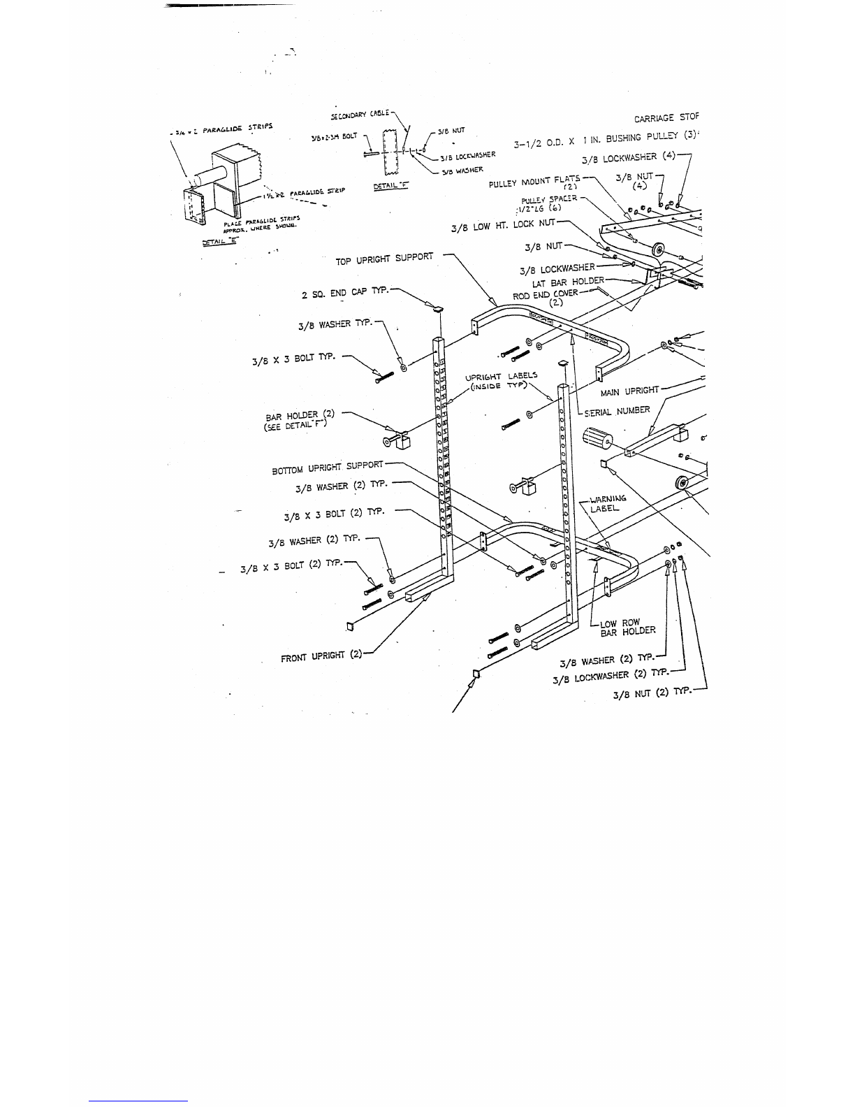
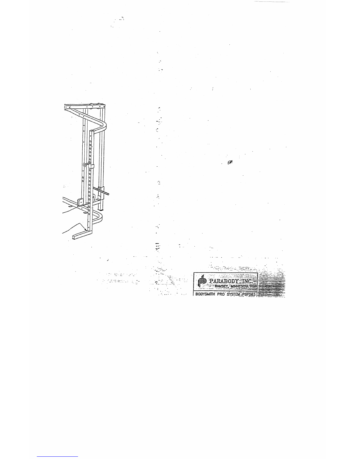
BODYSMITi-I PROSYSTEM ASSEMBLY INSTRUCTIONS
Attach one (I) 1-1/4 SQ. RUBBERBUMPERto the CENTERof the CARRIAGESTOPon the
WEIGHT CARRIAGE.
Slide WEIGHTCARRIAGEdown over the REARUPRIGHTof the MAINUPRIC-;HT. (NOTE:
MAKESURETHAT THE WEIGHTPEG ONTHE WEIGHTCAP,.RIAGE IS FACING
TOWARDSTFIE FRONT OF THE MACHINE)
LOOSELYattach the two (2) PULLEYMOUNTFLATSto the REARand FROthTUPRIGHTSof the
MAINUPRIGHT,using two (2) 3//I X3 IN. BOLTS,two (2) 3/8 .IN. LOCKWASHERS,and two
IN. NUTS. (NOTE: THE HOLECLOSESTTO THE ENDON THE PULLEYMOUNTFLATS
SHOULDBE ASSEMBLEDTO THE REARUPRIGHT) (SEE DRAWING)
AT THIS TIME TIGHTENALL LOOSEFRAMECONNECTIONSMADETO THIS POI_N~.
LOOSELYattach two (2) 3-1/20.D. X1 IN. BUSHINGPULLEYand four (4) ID_ IN. LG.PULLEY
SPACERS(ONE ONEACHSIDE OF THEPULLEYS)ber, veen the PULLEYMOUNTFLATS
above the WEIGHT-CARRIAGE,using two (2) 3/8 X 3 IN BOLTS,two (2) 3/g IN. LOCKWASI-~RS,
and two(2) 3/8 IN. NUTS.
Slide the two (2) RODENDCOVERSover the ends of the LATBARHOLDER.
Slide the LATBARHOLDERover the PULLEYMOUNTFLATS,and LOOSELYassemble in place,
using one (1) 3/8 X 3-1/4 BOLT,and one (I) 3/g IN. HEIGHT LOCKNUT.(NOTE: USE ~
SECONDSET OF HOLESIN FROMTHE END) (SEE DRAWING)
LOOSELYassemble one (1) 3-1/20.D. X1 IN. BUSHINGPULLEY,and two (2) lg.~ IN. LG. PULLEY
SPACER(ONEONEACHSIDE .OF THEPULLEY)between the PULLEYMOUNTFLATSat the
FRONT,using one (I) 3/8 X3-I/4 IN. BOLTS,one (1) 3/8 IN. LOCKWASHER,and one (1) 318
NUT.
LOOSELYresemble one (I) 4-I/20.D. X 1 IN. BUSHINGPULLEYto the PULLEYBRACKETon the
UPRIGHTBRACEoft.he MAINUPRIGHT,using one (1) .3/8 X 1-3/4 IN. BOLT,one (1) 3/g
LOCKWASHER,and one (1) 3/8 IN. NUT.
LOOSELYassemble one (1) 3-1/’20.D. X I IN. BUSHINGPULLEYto the LOWROWPULLEY
HOUSINGof the MAINUPRIGHT,using one (1) 3/8 X !-3/4 IN. BOLT,one(1) 3/g IN.
WASHER,and one (1) 3/8 IN. NUT.
To assemble the PULLEYBLOCKSYSTEM,SECURELYassemble two (2) PAINTED
CONNECTORSaround two (2) 3-1/20.D. X 1 IN. BUSHINGPULLEYS,using two>(2) 3/11 X2
BOLTS,four (4) 3/~I IN. WASHERS,and two (2) 3/8 IN. LOWHEIGHTLOCKNLU2S.(NOTE:
HOLESIN THE PAINTED CONNECTORARE OVAL, MAKESUITE THATTHE PULLEYSAP~
AT THEIVlJ~J~IMUMWIDTH,SEE DETAILG)

093
17.
18.
19.
20.
21.
22.
NOTE:
23.
NOTE:
BODYSI~tTU PROSYSTEM ASSEMBLY INSTRUCTIONS
Attach one (1.) 3/4 X2 IN. PAP,.AGLIDESt’RIP and one (I) 1-1/2 X2 IN. PARAGLIDESTRIPto
ADJUSTABLEKNEESUPPORTas shown in (’DETAIL E) using the following steps:
A. Thoroughly ciean all surfaces where the PARAGLIDESTRIPSare to be attached.
B. Removethe paper backing from the PARAGLIDESTRIPSand firmly apply them to the shown
surfaces.
Assemble two (2) ROLLERPADSto the ADJUSTABLEKNEESUPPORT,using one (I) ROLLER
PADSHAr’-I’, and two (2) STARLOCKCOLLARS.
Insert one (I) 2 IN. SQ. ENDCAPinto the front end of the ADJUSTABLEKNEESUPPORT.
To use the ADJUSTABLEKNEESUPPORT, rum the KNEESUPPORTTUBEso that the ROLLER
PADSare vertical, tnse~ the pin into the desired hole, and rotate clockwiseuntil locked. (SEE
DtL, kWlNG)
Attach eight (8) I-1D- X 2 PARAGLIDESTRIPS to the BARHOLDERS,and SAFETYRAILS
shownin (DETAILF) using the following steps:
A. Thoroughlyclean all surfaces where the PARAGLIDESTRIPSare to be attached.
Removethe paper backing from the PARAGLIDESTRIPSand fLrmly apply them to all shown
surfaces.
To use the BARHOLDEP~,and SAFETYRAILSfollow the same procedure as in ~TEP20.
BEFORE PROCEEDING WITH CABLE INSTALLATION, UNRAVEL CABLE, AND REMOVE
AS MUCHSPIRALING AS POSSIBLE.
To install the PRIMARYCABLE(PB2827-I), start by inserting the end of the CABLE,WITHOV~Fthe
WI-IITE BALL between the TOP PULLEYand the LAT BARHOLDERon the PULLEYMOUNT
FLATS. (REMOVE PULLEY FOR EASE OF INSTALLATION)
Pull CABLEover TOP PULLEYuntil the WHITEBALLstops against the PULLEYand the LAT BAR
HOLDER.
Pull CABLEover and down the SECONDPULLEYof the PULLEYMOUNTFLATS. Run the
CABLEaround one of the PULLEYSof the PULLEYBLOCKSYSTEMand up to the THIRD
PULLEYof the PULLEY MOUNTFLATS.
Pull CABLEover and down the THIRDPULLEY,to the WEIGHTCARRIAGE.Attach the CABLEto
the WEIGHTCARRIAGE,using one (I) 5/16 IN. SNAPHOOK.(SEE DETAILC)
See CABLEROUTINGDIAGRAM(DETAIL A) for help in completing STEP 23.
IF THIS UNIT WILL BE ASSElVIBLED WITH OPTIONAL PEC DEC, STOP HERE ANDPdEFER
TO THE PEC DEC ASSEMBLYINSTRUCTIONS. COMPLETESTEPS #2 TH_RU # 1S. WHEN
THIS IS COMPLETED,SKIP STEP #24,AND CONTINUEON TO STEP #25 OF TIq’E MAIN
UNIT INSTRUCTIONS.

093
24.
25.
.26.
27.
29.
30;
BODYSMiTH PROSYSTEM ASSEMBLY INSTRUCTIONS
To install SECONDARYCABLE(PB2559-1), start by inserting the end of the CABLE,WITHOUTthe
WHITEBALL under the FRONT PULLEYin the LOWROWPULLEYHOUSINGon the MAIN
UPRIGHT. (REMOVE PULLEY FOR EASE OF INSTALLATION)
Push the CABLEunder the FRONTPULLEYand through the HOLEof the 1VLAINUPRIGHTto the
PULLEYon the UPRIGHTBRACEof the I~L~_IN UPRIGHT.Pull the CABLEuntil the WHITE
BALL stops against the FRONTPULLEYand the LOWROWPULLEYHOUSING.
Pull the CABLEaround the BRACEPULLEYand up to the SECONDPULLEYon the PULLEY
BLOCK SYSTEM. (NOTE: THE CABLE MUST BE ROUTED AROUNDTHE SECOND PULLEY
FROM THE REAR TO THE FRONT)
Pull the CABLEaround the SECONDPULLEYof the PULLEYBLOCKSYSTEM~nd down to the
first HOLEabove the larger set of HOLESon the MAINUPRIGHT.Attach the end of the CABLEto
the MAINUPRIGHT,using one (I) 3/8 X 2-3/4 IN. BOLT.one (!) 3/8 IN. WASHER,one (I) 3/8
LOCKWASHERand one (1) 3/8 IN. NUT. (SEE DETAIL
See CABLEROUTi~NGDIAGRAM(DETAIL A) for help in completing STEP 24.
TIGHTEN ALL LOOSE PULLEY CONNECTIONS MADETO THIS POINT.
Slide four (4) I X 1~ IN. GRIPSover each end of both the LATBAR,and the LOWROWBAR.(NOTE:
IF A LUBRICANT IS REQUIRED, RUBBING ALCOHOL THOROUGHLYCOAXING
INSIDE OF THE GRIP IS THE BEST MATERIALTO USE) (SEE DETAIL AND B)
Attach the LAT BARto the PRIMARYCABLE, and the LOWROWBARto the SECONDARY
CABLE,by using two (2) 5/16 IN. SNAPHOOK.(SEE DETAILA AND
To adjust the LOWROWBAR. Remove the LOWROWBARfrom the 5/16 IN. SNAPHOOKon the
SECONDARYCABLE,and attach the 24 LINKCHAIN.Attach another 5/16 IN. SNAPHOOKto the
LOWROWBA:Rand adjust it to the desired CHAINLINK. (SEE DETAILB)
Attach two (2) sets of UPRIGHTLABELS(designated #1 to #21)to the inside surface of both ~0~
UPRIGHTS. (SEE DRA~VING)
To use the LOWROWFOOTBRACE,slip it over the BASELEGS,and up against 15ae UPKIGHTSof
the FRONT UPRIGHTS. (SEE DRAWING)

093 BODYS!Vf!TN PROSYSTEM ASSE!VLBLY INSTRUCTIONS
~~ S~ SNAP ~OO~ ~ FASTENED ~EFO~ DOLNG
EXERCISES
"~ WARNING
~’
DO NOT OPERATE TIIIS IV!ACH!NE W!TI-! LAT BAR OFF SAFETY
HOOKS
EXCEPT DURING I~IGH PULLEY EXERCISES
!!!WAR.N]:NG!:!
TI:~ LAT BAR IS NOT TO BE USED FOR PULL-UPS
!!! NOTE!!!
PLACE LOW ROW BAR IN LOW ROW BAR HOLDERS WHEN NOT IN
USE

TOP UPRIGHT SUPPORT ~ ,.3/8 LOCKWASHE:R
I.AT BARHOLE
MAIN UPRI
BARHOLDER(2)
(~:EI:::~TAIL"F’) ;ERIAL.NUMBER
FRONT UPRIGHT
ROW
BAR HOLDER


\\
DETAIL’A"
3/Bx 3-~,/~.BOLT(2)
NUTTYP.
LOCKFh’ASNER
WASHERTYP.
KNEE SUPPORT
(SEE DETAIL
NU’r(2).
LOCKWASHER(2.)
~/20.D. X 1 IN BUSHING
NUT(2)

(5{~: DETAI L’F"
LOWROWFOOT BRACE
Table of contents
Other ParaBody Home Gym manuals

ParaBody
ParaBody PBF410A User manual

ParaBody
ParaBody 950102 User manual

ParaBody
ParaBody Parabody 805101 User manual

ParaBody
ParaBody 350 User manual

ParaBody
ParaBody 889 User manual

ParaBody
ParaBody GS6 User manual

ParaBody
ParaBody 435104 User manual

ParaBody
ParaBody 828 User manual

ParaBody
ParaBody 94 User manual

ParaBody
ParaBody 777101 User manual

ParaBody
ParaBody 425104 User manual

ParaBody
ParaBody cm3 User manual

ParaBody
ParaBody PBF060 User manual

ParaBody
ParaBody Parabody 805 User manual

ParaBody
ParaBody 220 User manual

ParaBody
ParaBody PBF405B User manual

ParaBody
ParaBody 336101 User manual

ParaBody
ParaBody PBF502 User manual

ParaBody
ParaBody GS6 User manual

ParaBody
ParaBody 880 User manual