manuals.online logo
Brands
  1. Home
  2. •
  3. Brands
  4. •
  5. Paradox
  6. •
  7. Control Unit
  8. •
  9. Paradox Spectra Digiplex NE APR3-HUB2 User manual

Paradox Spectra Digiplex NE APR3-HUB2 User manual

INTRODUCTION
The APR3-HUB2 is a
non-addressable module that
extends and divides the control
panel’s bus into two completely
isolated bus outputs (two for each
connected APR3-HUB2). It extends
the bus by regenerating the signal
between the control panel and its
modules. Should one bus output
experience trouble or tampering, the
other will remain unaffected. The
hub monitors the signal between the
control panel and modules on each
output. If the hub detects a loss of
signal integrity it will cut off the
troubled output until proper
communication is reestablished.
If a hub’s output experiences trouble or tampering, the control panel
will generate a missing module trouble for every module connected
on that output.
INSTALLATION
Connecting the APR3-HUB2
Connect the APR3-HUB2’s four input terminals labelled RED, BLK, GRN,and
YEL to the corresponding terminals of the control panel as shown on the back
page (Figure 2 “Connecting the APR3-HUB2”).
Extending the Bus
The APR3-HUB2 has two independent bus output terminals (labeled “OUT”) to
connect system modules. From a hub, you can connect modules in a serial or
“daisy-chain” configuration up to a distance of 3000ft (914m) for Digiplex and
DigiplexNE panels and 250ft (76m) for a Spectra panel as shown on the back
page (Figure 2 “Connecting the APR3-HUB2”).
Each hub on the bus requires the connection of two power
supplies (one for each bus output terminal). Use either an
external power supply such as the PS-817 for Spectra or a
supervised power supply such as the DGP2-PS17 for Digiplex
and DigiplexNE. In addition, each power supply requires its own
transformer. Alternate configurations may result in improper
operation or damage to the system.
The APR3-HUB2 is non-addressable, therefore you can connect an
unlimited amount of hubs to the bus network without affecting the
total number of modules supported by the control panel.
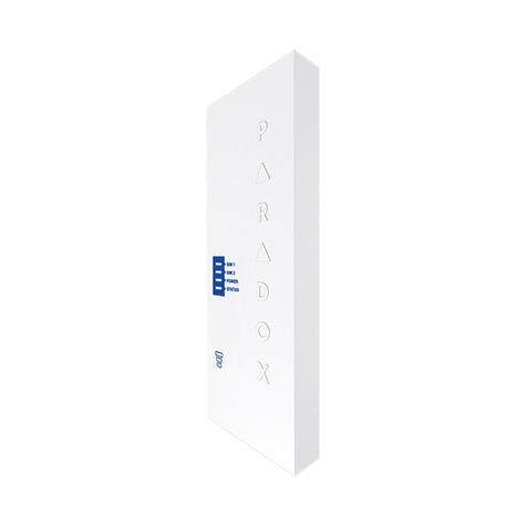
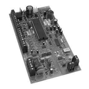
Figure 1: Overview of the APR3-HUB2
Visual Feedback
The APR3-HUB2 has on-board LEDs to display activity status. These are:
WDG LED: Flashes to show proper hub operation.
ERROR LED: Flashes to show a network fault.
DATA LED: Flashes to show network communication
between modules to control panel.
Troubleshooting
In the event that LEDs display the following status:
WDG LED does not flash: • Verify that the power supply for the input
is properly connected.
ERROR LED Flashes: • Verify that the power supply for the output
is properly connected.
• Verify for wire shorts between the output’s
GRN and BLK wires.
• Verify for wire shorts of connected
modules on the affected output.
• Remove any relay, hardwired, or non bus
modules connected on the output, as this
will affect communication.
SPECIFICATIONS
Power input: Typically 12-16Vdc
Current consumption: Typically 24mA. (50mA max)
Distance from panel: Digiplex/DigiplexNE:
18AWG = 3000ft (914m) or
22AWG = 1000ft (305m)
Spectra:
18AWG or 22AWG = 250ft (76m)
Distance of each output: Digiplex/DigiplexNE:
18AWG = 3000ft (914m) or
22AWG = 1000ft (305m)
Spectra:
18AWG or 22AWG = 250ft (76m)
Operating temperature: 0°C to 50°C (-4°F to 122°F)
Compatibility: Any Spectra, Digiplex, or
DigiplexNE control panel
Since the APR3-HUB2’s is non-addressable, the Winload software
will not recognize the APR3-HUB2. Winload will recognize
addressable modules connected to hubs throughout the bus
network.
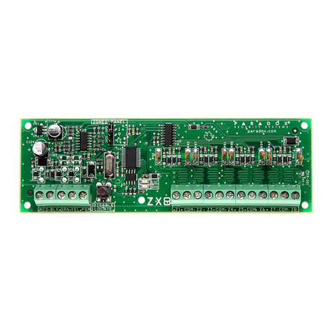
Figure 2: Connecting the APR3-HUB2
The APR3-HUB2 is non-addressable,
therefore you can connect an unlimited amount
of hubs to the bus network without affecting
the total number of modules supported by the control panel.
© 2002 Paradox Security Systems Ltd.
Winload, Digiplex and DigiplexNE are trademarks of Paradox Security Systems.
To o t h e r
modules
To other
bus
modules
bus
To o t h e r
bus
modules
From other modules or a
Spectra, Digiplex, DigiplexNE
control panel
12Vdc 12Vdc
Power supply with
dedicated transformer dedicated transformer
dedicated transformer
Power supply with
Power supply with
Output 1
Output 3 Output 4
WDG LED
WDG LED
12Vdc
12Vdc
Power supply with
dedicated transformer
Output 2
To other
bus
modules

Other Paradox Control Unit manuals

Paradox IP100 User manual

Paradox

Paradox IP100 User manual

Paradox PCS300 User manual

Paradox

Paradox PCS300 User manual

Paradox APR3-ZX4 Operating instructions

Paradox

Paradox APR3-ZX4 Operating instructions

Paradox IP150 User manual

Paradox

Paradox IP150 User manual

Paradox MG-RCV3 User manual

Paradox

Paradox MG-RCV3 User manual

Paradox RPT1+ User manual

Paradox

Paradox RPT1+ User manual

Paradox PCS265LTE Installation guide

Paradox

Paradox PCS265LTE Installation guide

Paradox Digiplex EVO ZX8D User manual

Paradox

Paradox Digiplex EVO ZX8D User manual

Paradox IP150 Operating instructions

Paradox

Paradox IP150 Operating instructions

Paradox PCS265 User manual

Paradox

Paradox PCS265 User manual

Paradox PCS265 LTE Installation guide

Paradox

Paradox PCS265 LTE Installation guide

Paradox DGP-LSN4 V1.1 Operating instructions

Paradox

Paradox DGP-LSN4 V1.1 Operating instructions

Paradox VDMP3 User manual

Paradox

Paradox VDMP3 User manual

Paradox Digiplex EVO EVO192 V7.11 Operating instructions

Paradox

Paradox Digiplex EVO EVO192 V7.11 Operating instructions

Paradox ZX82 User manual

Paradox

Paradox ZX82 User manual

Paradox Digiplex APR-ADM2 User manual

Paradox

Paradox Digiplex APR-ADM2 User manual

Paradox ZX8 User manual

Paradox

Paradox ZX8 User manual

Paradox Magellan VG-RTX3 User manual

Paradox

Paradox Magellan VG-RTX3 User manual

Paradox IP150 User manual

Paradox

Paradox IP150 User manual

Paradox Digiplex EVO PRT3 Installation manual

Paradox

Paradox Digiplex EVO PRT3 Installation manual

Paradox ZX82 User manual

Paradox

Paradox ZX82 User manual

Paradox PCS265 LTE Installation guide

Paradox

Paradox PCS265 LTE Installation guide

Paradox IP150+ User manual

Paradox

Paradox IP150+ User manual

Paradox MG-RCV3 User manual

Paradox

Paradox MG-RCV3 User manual

Popular Control Unit manuals by other brands

SPORTident BS Series instructions

SPORTident

SPORTident BS Series instructions

National Instruments NI-9208 Getting started

National Instruments

National Instruments NI-9208 Getting started

Siemens ST950 Installation Method Statement

Siemens

Siemens ST950 Installation Method Statement

Honeywell D15SN A Series installation instructions

Honeywell

Honeywell D15SN A Series installation instructions

National Instruments NI 9930 user guide

National Instruments

National Instruments NI 9930 user guide

Satronic MMG 810.1 Instructions for use

Satronic

Satronic MMG 810.1 Instructions for use

GMI D5096S-106 instruction manual

GMI

GMI D5096S-106 instruction manual

Broadcom BCM7405 General information

Broadcom

Broadcom BCM7405 General information

Novatek NT93403-05X manual

Novatek

Novatek NT93403-05X manual

Climax VM2350 operating manual

Climax

Climax VM2350 operating manual

ELTEC IPIN-22 Hardware manual

ELTEC

ELTEC IPIN-22 Hardware manual

Viessmann EM-P1 Installation and service instructions for contractors

Viessmann

Viessmann EM-P1 Installation and service instructions for contractors

Seeed Beaglebone green manual

Seeed

Seeed Beaglebone green manual

ADTRAN Job Aid+ Total Access 5000 1442910G1C manual

ADTRAN

ADTRAN Job Aid+ Total Access 5000 1442910G1C manual

Lamtec ETAMATIC V quick reference

Lamtec

Lamtec ETAMATIC V quick reference

RFL Electronics GARD 8000 instruction manual

RFL Electronics

RFL Electronics GARD 8000 instruction manual

iWave iW-RainboW-G34M Hardware user's guide

iWave

iWave iW-RainboW-G34M Hardware user's guide

Dimension One Spas D1 SpaIQ user manual

Dimension One Spas

Dimension One Spas D1 SpaIQ user manual

manuals.online logo
manuals.online logoBrands
  • About & Mission
  • Contact us
  • Privacy Policy
  • Terms and Conditions

Copyright 2025 Manuals.Online. All Rights Reserved.