Philco 121 User manual

• • • • • • • • • mi,d,d, 38-2,Cork. 121
SERVICE BULLETIN NO
■
2 94 lor members of
RADIO MANUFACTURERS SERVICE
Electrical Specifications
Model 38-2, Code 121, is an eleven tube, A. C. operated super -
heterodyne receiver with three tuning ranges covering the frequen-
cies listed below,and employs the PHILCO AUTOMATIC TUNING
DIAL MECHANISM . Additional design features incorporated in
this receiver are: Magnetic Tuning Control oh the broadcast tuning
range; Automatic Volume Control; Bass Compensation; Special
Push-pull Pentode Audio Output circuit designed for the reduction
of harmonic distortion; Four Point Tone Control ; R. F. Circuit
completely shielded and contained in one unit; all aligning compen-
sators accessible from the top of the chassis .
POWER SUPPLY:
Voltage
115
115
115/ 230
Frequency
Cycles
50 to 60
25 to 40
50 to 60
Power
Consumption
140 Watts
140 Watts
140 Watts
Different transformers are requir ed for operation on the voltages
and frequencies listed above . The part numbers for these transc
formers are listed on page 3. A.special transform.er for operatio n on
either 115 or 230 volt-SO to 60 cycles A. C. power circuit can be
obtained. This transformer is provided with a plug and socket for
selection of either"voltage rating. Place the plug with arrow pointing
toward voltage being used.
FREQUENCY RANGES: Three.
Range one-530 to 1720 K. C.
Range two-2.3 to 7.4 M. C.
Range three-7.35 to 22.0 M. C.
INTERMEDIATE FREQUENCY: 470 K. C.
AUDIO OUTPUT: 7 Watts.
PHILCO TUBES USED: 6U7G, R. F. Amplifier; 6A8G, Det . Osc.;
6N7G Osc. Contro l; 6K7G, I. F. Amplifier; 6H6G, Magnetic
Tuning Discriminator; 6R7G, 2nd Det ., A.V.C., 1st. Audio; 6J5G,
Audio Phase Inverter; 6J5G, 2nd Audio; Two 6F6G, Output; and
5X4G, Rectifier.
TONE CONTROL: Four Point.
A. Brilliant-for speech.
B. Bright-for normal reception of music.
C. Mellow-first noise-reducing stage.
D. Deep-Nois e-reduci ng for distant reception.
PHILCO SPEAKER: H32.
CABINET: Type XX.
Aerial Connections
To obtain the full advantage of the sensitivity of this receiver the
Philco High Efficiency Aerial supplied with the instrument must
be used. Connect the aerial as follows:
The aerial terminal panel located on the rear of the chassis , con-
tains three terminals marked "Red," "Blk" and "Gnd". Connect
the red and black wires of the aerial lead in (Transmission Line ) to
the "Red" and "Blk" terminals respectively. Connect the "Gnd"
terminal to a good ground source. If a temporary aerial is used,
connect it to the "Red" terminal.
A PHILCO Service Plan
!VOLTAGES MEASURED rRoM 100t3SV~
~
SOCKET CONTACTS TO
ll [ C.t1fl llll ~OCl<.CT CHASSIS
~
-~
...ou ,. 1Co O., lO P o r
~
RF
•0 -(11 TR-Sfl)IIW[III bSV. 6U7G ' H o
-···-- 0 ... .
(?{~;:i) lS0V. 100V.~ 001 -
~
b.lH C.
i€)1 ""~ 2ND AUDIO
b.lV.At. 6JSG
2ND DET
REc.Tiiirn A VC
6.lUC . 1ST AUDIO
~X 4 G 330 6 A7G
t
2~
~
OISCRIMIN.~
rn .~ ni:·:· 6 H 6G PoQ
OUTPUT ~~o
~
0
6.lV.At.
6f6 G Go OSC·CONT ROL 5.lV.~ 2so v.4
_foov. ·~
2bo:H:is s v. 6 N7G OA
~
,9
~
190v.-eto ~.,_G
6.m~
~
H ot
OUTPUT ~~o ,~ov.6.lV.At. b.lV.lt . ,:av .
DEJ; ~ ~C
~
1.r PHASE
6'6G '~Jf 6 K7G INVERTER
OSC.P. 130v.~ a0 6J 5G
260V. ZSH . Ost.C.9
100V.
260v.
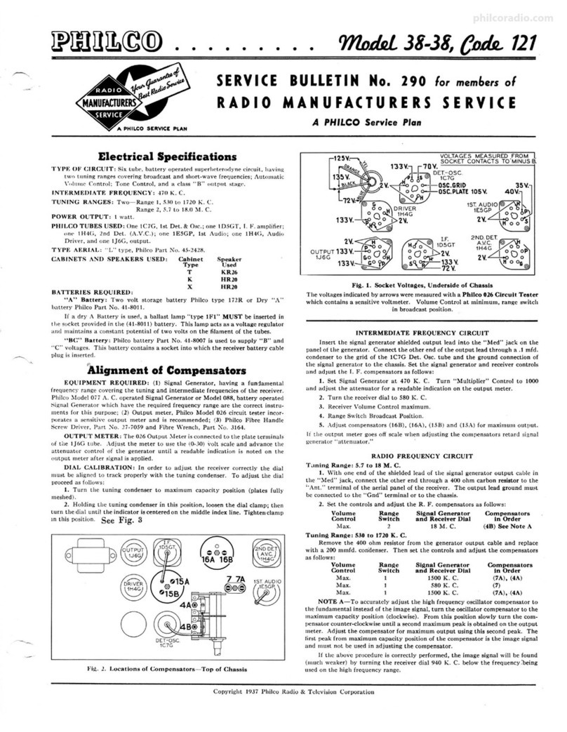
Fig. 1. Underside View of Chassis showing Socket Voltages
The voltages indicated by the arrows were measured with a Philco 026 Circuit
Tester, which contains a sensitive voltmeter. Line voltage 115 A. C.-Volume
control minimum-Dial set at point where no signal is present-Range Switch
in broadcast position.
Automatic Tuning Mechanism
Service Data
Service data and a comp lete parts list for the Automatic Tuning
Mechanism of this receiver will be found in Service Bulletin 273.
When referring to bulletin 273, use the dial parts list for Model 37-10
as the same parts are used on Model 38-2. There are four automatic
dial parts, however, which differ from those shown in bulletin 273.
These parts are marked with an asterisk on page 3 of this bulletin.
Service Notes
For reference between illustrations, Parts List, and for replacement
of parts, the various diagrams in this bulletin are marked with
"circled numbers" indicating a particular part .
Physical views of the R. F. transformers are shown on page 2.
Each transformer is marked with the corresponding schematic dia-
gram circled number. The connections of the R. F. transformer are
numbered to indicate the connecting points in the circuit diagram
which are correspondingly marked.
The colors of the I. F. transformer leads are marked on the
schematic diagram.
Range switch lugs are marked with a letter and number-example
(A2)-indicating the connecting point in the circuit diagram. Each
range switch section is marked with a letter indicating the position
of the section from the rear of the chassis. Section "A" is used in
the oscillator circuit. Section "B" the "RF" circuit, and Section
"C" the antenna circuit.
The colors of the connections on the power transformer and speaker
unit are also marked on the schematic diagram.
Copyright 1937, Philco Radio & Television Corporation
philcoradio.com

Page2 PHILCO SERVICE BULLETIN
r
~
T I
/ R.f. ~TUN ING CONOCNSCA / OET.-OSC . /
/ 6U7G ,' 6A8G /
.' ,------, ! -
./:(BA
@"'ITT------
fLOOD LA•~ -=- l
- flLAM[NT ~--------~~'......:---==---1---==--~::::.---=__J
4~~-1
'--@ ®'-+ ,,··
,'
.!_,,
/
... (95)
fl [ lrc;;ll
No. 294
Jl,®
°l~
~
1:
gTv.:\
q~®
~
---Ila
u
i
&Pia.Pluc.lr.ono" Vil-,
SPEAK[l WlllNC.
L[TT[A S INDICATE POSITI ON or SWITCH .WAf[AS
F"ROM ACAA or CHASSIS' (BOTTOM Vl[W )• ,,,t''••• _BLUl I
~
I '
~
I IOOUN·WHITL·T•· I I
C2'c'l-<e>E12
ALL RANG( $WIT CH[$ SHO WN IN POSITION No I (8 ' 0C'ST).
SOLID ARCA INDICATES ACAR Of SWITCH WAf'[A .
SHADCD ARCA INOICAlES fAONT or SWITCH WAf[A .
-- ···----· ·--- - ··- ··
H~AN:JtUHMLI'~> ~"Uffli WITH IND[ )( $L OT IN fAONT
211 11 ~3 2~1 '[ ~· ~3
. '. '
~
J'
~
'' :H,~..
~
'
<DR.'!.~I ©A~~-z ®A....
~~t
l @A.-:.~,I ®...
~
~[
z @A.':.~cl ®A2~cfc 1(fg)R._oNsc.'i2
--- - ---- ---- - --- --- ---
8__ !.Ut~
6L[SS .1.n.8L.O.O,
Fig. 2. Schematic Diagram
Model 38-2, Code 121
) )
~t
l ~@ •e~ i"'-23 n
I.F'.=470 K.C.
)
philcoradio.com

No. 294
Replacement Parts
Schem. Part
No. Desuiptlon No.
1 Antenna Transformer (Range 1) . 32-2575
2 Antenna Transformer (Range 2).. . 32-2576
3 Antenna Transformer (Range 3). 32-2573
4 Compensator, Antenna (Range 3) 3-1-6160
5 Condenser (.05µf tubular) ..... . . .-. .. .. 3M519
8 Condenser (.05µf-.05µf, Bakelite) . . . 3615DG
7 Resistor (51,000 0, ½ Watt). .... . 33-351339
8 Tuning Condense r Aasemhly .... 31-2075
9 Resistor (.100o, ½ Watt) .. . .. 33-110339
10 C'-ondenser(.05 µf, tubular) ... . . .. .... 30-4020
11 R. F. Transformer (Range I) .. . .. .... 32-2379
12 R. F. Transformer (Range 2) . 32-2382
13 R. F. Transformer (Range 3)..... . . . 32-2385
14 Condenser (5 µpf, Mica). . . . . . . .. . . 30-1097
J:8~::'f.'.::.~p~~i~-6
Ra~g-e3):: : : :: 31-6212
17 Condenser (.05 µf, Tubular) 3M519
18 Compensator Osc. (Range!) . .... . .... 31-6212
19 Osc. Tran.sformer (Range I) .. .. .. .. . . . 32--2373
20 Osc.Transformer (Range 2) . . .. 32--2383
21 Osc.Transform er (Range 3) . ... . . . . . . 32-2386
22 Compensator (Range 1 Series) . .. . . . . 31-6151
23 Condenser (1605 µpf, Mica) .. . . . . . . . . 31--6201
24 Resistor (2000, ½ Watt) . . ..... . . 33-170339
25 Condenser (.01 µf, Tubular).... 3M479
26 Condenser (IIOµµf, Mica) .. . 30-1031
27 Condenser (110 µpf, Mica).. 30-1031
28 Resistor (99,000 0, ½ Watt) 33-399339
29 Resistor (85 0, ½ Watt-) ... . 33-085339
30 Resistor (99,000 0, ½ Watt) 33-399339
31 Condenser (.3 µf, Bakelite) 6287DG
32 ·Compensator (2 Sections) .... . . . . . . . . 31--6211.
33 Condenser (250µµf, Mica) . .. . ... . . . . 30-1032
34 Resistor (32,000 0, ½ Watt). . 33-332339
35 Resistor (10,000 0, ½ Watt). . .. 33-310339
38 Condenser (4280 µµf, Mica) 31--6202
37 1st. I. F. Transform er.. .. . .. . . . 32--2604
38 2nd I. F. Transform er .. . . . . . 32--2362
39 Compensator ... . . . . . . . . . . . . 31-6203
40 Condenser (110 µµ[,Mi ca). . . . . . 30-1031
41 Resistor (1.0 Meg., ½ Watt) .. . 33--510339
42 Resistor (1.0 Meg., ½ Watt) 33--510339
43 Resistor (51,0000, ½ Watt).. . . . 33-351339
44 Resistor (330,000 0, ½ Watt)... 33--433339
45 Condenser (.Iµ[, Tubul ar)... . 3M455
46 Condenser (.05, Bakelite) . . . . . 3615SG
47 Resistor (1000 0, ½ Watt) . . . 33--210339
48 Resistor (330,000 0, ½ Watt) . . 33--433339
49 Resistor (2.0 Meg., ½ Watt) .. . 33-520339
50 Resistor l2.0 Meg., ½ Watt) .. 33-520339
51 Resistor (1.0 Meg.,½ Watt) . 33--510339
52 Resistor (1.0 Meg., ½ Watt). . . . . . . 33-510339
53 Condenser (llOµµf, Mica). . . . . . . .. 30-1031
54 Condenser (110 µµ[,Mi ca) . . . . . . . .. 30-1031
55 Resistor (490,0000, ½Watt) . ... . 33-449339
58 Resistor (490,0000, ½Watt) ........ . . 33--449339
57 Condenser (.15 µf- .15µ[, Bakelite) ... . 6287DG
58 Condenser (.006µ[, Tubular) .. . . .. 30-4445
59 Resistor (25,000 0, ½ Watt) .. . 33--325339
60 Condenser (.I µf, Tubular) ... .. 30-4455
61 Condenser (.01 ,.r,Tubular) ... . 30-4479
62 Condense r (.015 µf, Tubular) . .. 3M226
63 Resistor (51,000 0, ½ Watt). 33-351339
64 Volume Control 33-5233
85 Resistor (1.0 Meg., ½ Watt). 33-510339
88 Resistor (99,000 0, ½ Watt). . 33-399339
87 Resistor (240,000 0, ½ Watt) 33--424339
88 Condense r (.006 µ[,Tubu lar) .. 30-4467
89 Resistor (490,000!!, ½ Watt) . 33-449339
70 Conden.ser (.I µf, Tubular) .... . ...... 30-4499
71 Cond enser (.03 ,J-.03 µf, Bakelite) . 8318DU
72 Resistor (1.0 Meg.,½ Watt) .. . . .... .. 33-510339
73 Audio Shorting Switch (Parts (6) and
(16) Bulletin 273) .... : .. . . .. .. .
74 Tone Control. .. .. . . . . . . . . . . . . . . . . . . . 42-1268
75 Resistor (7,500 !l - 9,000 O Wire
Wound) . . ....... . . . . . . . . . . . . . 33-3320
78 Electrolytic Condenser (4 µf- 3 µf) .... . 30-2243
List
Price
$0.70
.70
.70
.30
.20
.40
.20
.20
.20
.40
1.00
1.20
.20
.20
1.60
.70
.70
.40
.40
.20
.20
.20
.20
.20
.20
.20
.40
.25
.20
.20
.50
2.20
3.30
.30
.20
.20
.20
.20
.20
.25
.35
.20
.20
.20
.20
.20
.20
.20
.20
.20
.20
.40
.20
.20
.25
.20
.20
.20
1.00
.20
.20
.20
.20
.20
.20
.40
.20
.75
.65
1.50
PHILCO SERVICE BULLETIN
Schem. Part
No. Deecriptlon No.
n Resistor (40,0000, 1 Watt). . . ..•... . 33-340439
78 Condenser (.03 µf, Tubular) 3M449
79 Condenser (.03 µ[,-Tubular) . .. . . . . . . . . 30-4449
80 Resistor (99,000!l, ½Watt) .·. . . ... . 33-399339
81 Resistor (490,000!l, ½ Watt).... .. 33--449339
82 Resistor (51,0000, ½ Watt) .. . . ... . 33-351339
83 Resistor (330,000 !l, ½ Watt)...... 33--433339
84 Resistor (40,0000, ½ Watt) . . . . . . . . 33-340339
85 Resistor (5,000 !l, ½ Watt) .. .. . ... . . . 33-250339
88 Resistor (3.10,0000, ½ Watt)...... 33--433339
87 Resistor (45,0000, ½ Watt)..... . 33-345339
88 Condenser (.03 µ[, Tubular)... . . . . . . 3M449
89 Resistor (99,000 !l, ½ Watt) .. ... ... 33-399339
90 Condenser (.006 µf, Tubular). .. . . . . 3M445
91 Condense r (.006 µ[, Tubular). . . . . . . . 3M445
92 Output Transformer ...... . . 32--7754
93 Cone&: Voice Coil Aasembly 36--3801
94 Resistor (88- 15-23 {l) . . 33--3321
95 Field &:Pot . Aasembly.. ... .. . ..... . . . 36--3941
96 Electro lytic Condenser. . .. . 30-2211
97 Electrolytic Condenser .... .. .. . . . . ... 30-2211
98 Condenser (.25 µf, Tubular)... . . . 3M446
99 Choke.. . . .. . ... . ........ . 32-7115
Lisi
Price
S0.20
.20
.20
.20
.20
.20
.20
.20
.20
.20
.20
.20
.20
.20
.20
1.50
1.40
.40
1.00
1.00
.25
I.SO
Fig. 3. Part Locations, Underside of Chassis
Schem.
No. Description Part
No.
100 Power Transformer (115V - 50-60
Cycles) . ... .... . ... . .... .. . ..... . 32--7869
PowerTran sformer( 115V,25-40cy~es) 32-7870
Power Transforme¥ (115/ 230V,
50-60 cyclesi .............. . . . .. . 32-7871
101 Condenser( .015µ[-.015µ[, Bakelite) .. 3793DG
102 A. F. C. Shorting Switch ... 45--2330
103 A. F. C. Switch 4Z-1.2"69
104 Flood Lamp Bulb .. 34-2064
105 Pilot Lamp . .... 34-2064
108 Wave Switch .. 42-1362
Automatic Tumng Mechanism (complete) 38-9145
Cable (Power) . . . . . . L-2183
Cable (Speaker) ... . 41-3329
Clip (R . F. Coils) .... .. . . . . . . 28--5002
Coupling (Tuning Condell3Cr) 31-1961
Coupling (Range Switch&: Mash) 38-8693
Knob (Range Switch) . . .. . . . . . . . 27--4326
Knob (Tuning} .. 27--4330
Knob (Vernier). .. . . . . 27--4331
Knob (Tone, Volume). . . 27-4332
Mtg. Rubher (Chassis) 27-4564
Mtg. Rubber (Rear of R. F. Unit) . .. . . 27-4197
Lisi
Price
S0.40
1.20
.09
.09
3.00
.40
.02
.80
.10
.10
.10
.10
.10
.08
Page 3
Schem. Part
No. Description No.
Mtg. Rubber (Front of R. F. Unit) .. .... .. 27-4581
Shield (R. F. Umt) .... . . . . . ... . . . _. . ... . . 38-8969
Shield (Tuhe) (Square) .. . .. . ............. 28-2726
Shield (Tuhe) (Round). .. . . . . . . . . . l!005
Shield Baoe (Square) . . . . . . . . . . . . . . . . . 28-2725
Socket Aasembly (Pilot Lamp} . 38-9100
Socket (6 prong) ...... . . . . . . . . . . . . . . . . . . 27-6086
Socket (7 prong} (6F6G tubes) . . .. .. . . . . . . 27--6057
Socket. (7 prong} .. ... .. . . .. . . . . ... . ..... 27-6087
Speaker H-32 .... ..... .. . . .. ..... .. ..... . 3tl-1299
Support (rearof R. F. Unit). . .. ... . . . . . . . . 38-8923
Terminal Panel (Antenna). . . .. . . . . . . . . . . . 38-8746
CABINETPARTS
B,ael Assembly ... . ...... . . . . ....... 38-8833
Cover (Back of cabinet) ... .. .. ..,. . . . . . . . . . 27-8!!64
AUTOMATICTUNINGMECHANISMPARTS
•Cover (handle). .. . .. .. . . . . . . . 28--5092
•Dial . . . . . . . . . . . . . . . . . . . . . . . . . . . . . . . 27-5358
Lisi
Price
S0.10
.10
.03
.11
.11
.11
.15
2.50
1.00
.50
•Dial Screen Holder ... . .. .... . . .. . ..... . . 31-2053 .75
•Escutcheon Aasembly (Station tahs)...... . 45--2472
•These Automatic Tuning Mechanism Parts differ from those
shownio Service Bulletin 273.
The Genuine PHILCO Replacement Parts listed above must be used to obtain the Accurate Balanced Performance built into this Philco Model
philcoradio.com

Page4 PHILCO SERVICE BULLETIN No. 294
Alignment of Compensators
EQUIPMENT REQUIRED: (l) Signal Generator, having a fundamental
frequency range covering the intermediate and tuning freQuencies of the receiver .
Philco Model 077 Signal Generator which has a fundamental frequency range from
115 to 36000 K. C. is the correct in•trument for this purpose;_ (2) Output Meter,
Philco Model 026 Circuit Tester incorporates a sensitive output meter and is recom-
mended; (3) Philco Fibre Handle Screw Driver, Part No . 27-7059 and Fibre Wrench,
Part No. 3164 .
OUTPUT METER: The 026 Output Meter is connected to the plate and
cathode terminals of one of the 6F6G tubes. Adjust the meter to use the (0-30)
volt scale and advance the attenuator control of the generator until a readable in-
dication is noted on the output meter after signal is applied to stage being adjusted.
DIAL CALIBRATION: In order to adjust the compensators of this receiver
correctly, the dial must be aligned to track properly with the tuning condenser . To
do this proceed as follows:
l. Loosen the set screws on the shaft coupling of the tuning condenser . Then
turn the tuning condenser until the plates are in the maximum capacity position .
Now turn the dial until the glowing beam indicator is on the INDEX LINE at the
low frequency end of Range 2. See Fig. 4. With dial and tuning condenser ia
this position, tighten set screws .
2. Turn the tuning condenser control until tile indicator is on the 2.2 M . C.
Mark.
3. With the dial in this position, loosen the shaft coupling set screws. Then
turn the dial until the indicator is again on the INDEX LINE. Tighten the set
screws in this position . Be careful when turning the dial that the position of the
tuning condenser is not disturbed .
INTERMEDIATE FREQUENCY CIRCUIT
A. Set the receiver and signal generator controls as follows:
l. Range Switch (Broadcast)
2. Volume Control (Maximum)
3. Magnetic Tuning Switch "out"
4. Tone control & A. C. switch first position .
5. Signal generator dial 470 K. C.
B. Connect the signal generator output
cable through a .1 mfd. condenser to the
grid of the 6A8G Del. Osc. tube and connect
the cableground to the receiver chassis.Now
adjust the following compensators for maxi-
mum output (38A), (39), (37B), and (37A).
RADIO FREQUENCY CIRCUIT
l. Set the controls as given under
"Intermediate Frequency Circuit" 1 to 4
and set the range switch, signal generator
and receiver dials as given under the adjust-
ments of each tuning range in the following
procedure.
Connect the Signal Generator output
cable into the "Med" jack of the generator
panei and connect the other end throu ·gh a
.l mfd. condenser to the "Red" terminal of
the receiver aerial panel (rear of chassis).
The ground connection of the cable should
be connected to the "Blk" terminal.
2. Adjust the "R. F ." compensators
for maximum output as follows:
Tuning Range: 530 to 1720 K. C.
fUflE l'ORE
SLOWLY A
LIN[S ·•t
TUllj[ LON
~--- Pl'IJIIS Ar
NUMBER
,,.. THE
ER NU~
INDEX LINE
Fig. 4. Dial Calibration
Compensator
■
Range Switch
Position
1
Signal Generator
and Receiver Dial•
1550 K. C. In Order
(18), (8B) and (8A)
1 580 K. C.
1550 K. C.
Tuning Range 2.3 to 7.4 M. C.
Range Switch
Position
2
Signal Generator
and Receiver Dial
6.0M. C.
Tuning Range 7.35 to 22.0 M. C.
Range Switch
Position
3
3
Signal Generator
and Receiver Dial
20.0 M . C.
20.0 M . C.
(22) Roll gang. Note B
(18), (8B), (8A)
Compenaatora
In Order
(32)
Compensator•
In Order
(32A), (15), (4)
Roll Tut .ting condensers when ad-
juRtlng (15) and (4). See Note B.
Check Image at 17.060. See Note A.
(32A)
,,,----._
32
OUTP UT .,
0
~
~
32A (PHASE]
,,,----._ INVERTER
OUTPUT M_J~s-:1
~
~15 ,=
~
38Ao0til38801scR1"
@ 0
~
~H&;d
•4 390
21110
-OCT
A VC
C, 0 1ST AUDIO
~
Fig. 5. Compensator Locations
MAGNETIC TUNING CIRCUIT ADJUSTMENTS
l. Set the Magnetic Tuning switch in the "out" position.
~
2"°AU010
kJ~~
2. Turn the signal generator indicator to 1000 K . C. and adjust the "Attenu-
ator" control for a weak signal.
3. Adiitst volume control for a readable indication on the output meter .
4. Now tune the receiver dial for maximum output at 1000 K. C. The dial
must be tuned very accurately to the 1000 K. C. signal in order to make the following
adjustment correctly .
5. Turn the Magnetic Tuning switch "in" and adjust compensator (.18B)
for maximum output.
The above adjustments are now checked for accuracy as follows :
FREQUENCY TEST
With the 1000 K. C. signal tuned for maximum output turn the Magnetic
Tuning control back and forth; that is, from the "out" to "in" position. The read-
ing of the output meter should not change in either position. If the output meter
reading changes, the above magnetic tuning circuit ad.justments should be repeated. ,,-..._
A further check on the Magnetic Tuning adjustment is to very carefully tune in
a broadcasting station and turn the switch from the "out" to the "in" position.
With the switch in either position, the tone of the station being received should not
change. If a change of tone or hiss develops repeat the above Magnetic Tuning
Adjustments. SENSITIVITY TEST
l. _To check the magnetic tuning circuit for sensitivity, turn the magnetic
tuning switch to the "out" position, and tune in the 1000 K . C. signal. Then adjust
the "attenuator" control of the signal generator for a good audible signal. Approx-
imately 20 volts on the output meter.
2. Now detune the signal (first above and then below) the 1000 K . C. mark to a
point at which the signal is weakly heard. At each p0int turn the magnetic tuning
control "on". When the control is turned on the signal should return to normal
output strength . If the magnetic tuning circuit does not pull the signal into reson:
ance, the compensator should be carefully readjusted.
NOTE "A"-To accurately adjust the high frequency oscillator compensator
lo the fundamental instead of the image signal, turn the oscillator compensator to
the maximum capacity position (clockwise). From this position slowly turn the
compensator counter-clockwise until a second maximum peak is. obtained. on the
output meter. Adjust the compensator for maximum output using this second
peak . The first peak from maximum capacity position of the compensator is the
image signal and must iiot be used in adjusting the compensator .
If the above procedure is correctly performed, the image signal will be found
(much weaker) by turning the receiver dial 940 K. C. below the frequency being
used on any high frequency range.
NOTE "B"-When adjusting the low frequency compensator of Range One
(Broadcast) or the antenna and R . F. compensators of the high frequency tuning
ranges; the receiver Tuning Condenser must be adjusted (rolled) as follows: First
tune the compensator for maximum output, then vary the tuning condenser of the
receiver for maximum output about the frequency dial mark. Now turn the com-
pensator slightly to the right or left and v,lry the receiver tuning condenser for
maximum ot tput. If the out reading increases, turn the compensator in the same
direction a trifle more. and again vary the tuning condenser for maximum output.
If the output decreases, set the compensator in the opposite direction. This pro-
cedure of first setting the compensator and then varying the tuning condenser is
C:ontinued until there is no further gain in output reading.
August 1937
PHILCO RADIO AND TELEVISION CORPORATION
Parts and Service Division
Philadelphia, Pa. Printed in U.S. A.
philcoradio.com
Other manuals for 121
8
This manual suits for next models
1
Other Philco Radio manuals

Philco
Philco 37-620 User manual

Philco
Philco 200 User manual

Philco
Philco PHOTOFACT 49-1150 User manual

Philco
Philco 37-650 User manual

Philco
Philco 66 User manual

Philco
Philco 121 User manual

Philco
Philco PRR1005BT User manual

Philco
Philco 611 User manual

Philco
Philco 37-116 User manual

Philco
Philco 39-55 User manual

Philco
Philco 121 User manual

Philco
Philco 77 User manual

Philco
Philco 643 User manual

Philco
Philco 37-675 User manual

Philco
Philco D-592 User manual

Philco
Philco 15 Series Reference manual

Philco
Philco 650 User manual

Philco
Philco 37-640 User manual

Philco
Philco 96 User manual

Philco
Philco 37-660 User manual