Philco 121 User manual

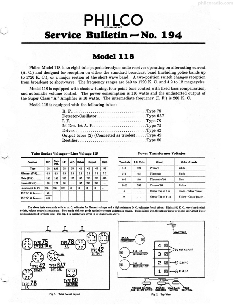
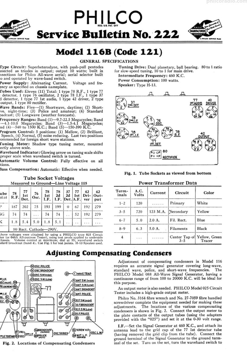
• • • • • • • • • <mi,dJll38-t,CorlR._121
SERVICEBULLETINNo. 293 for members of
RADIO MANUFACTURERS SERVICE
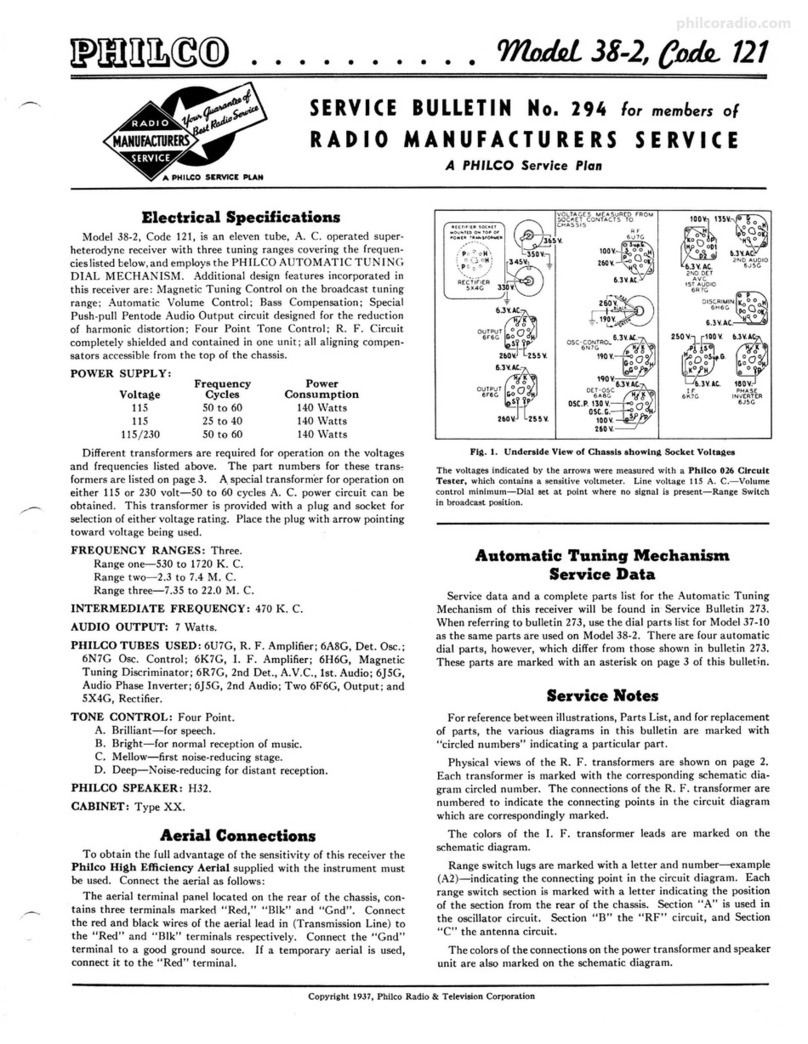
Electrical Specifications
Model 38-1, Code 121 is a twelve-tube, A.C. operated superhetero-
dyne receiver with three tuning ranges covering the frequencies listed
below and employs the Philco Automatic Tuning Dial Mechan-
ism. Additional design features incorporated in this receiver are :
Magnetic Tuning Control on the broad cast tuning range ; Automatic
Volume Control; bass compensation; special push-pull pentacle audio
output circuit designed for the reduction of harmonic distortion ;
Adjustable Iron Core I. F. Transformers; Four Point Tone Control ;
R. F. Circuit completely shielded and contained in one unit; all
aligning compensators accessible from the top of the chassis .
POWER SUPPLY: Voltage Frequency Power
Cycles Consumption
115 SOto 60 150 Watts
115 25 to 40 150 Watts
115 or 230 50 to 60 150 Watts
Different transformers are required for operation on the voltages
and frequencies listed above . The part numbers for these trans-
formers are listed on page 3. A special transformer for operation on
either 115 or 230 volt-SO to 60 cycle A.C. power circu it can be
obtained. This transformer is provided with a plug and socket for
selection of either voltage rating . Place the plug with arrow pointing
toward voltage being used.
FREQUENCY RANGES: Three .
Range one-530 to 1720 K. C.
Range two-2 .3 to 7.4 M. C.
Range three-7.35 to 22.0 M. C.
INTERMEDIATE FREQUENCY: 470 K. C.
AUDIO OUTPUT: 10 watts.
PHILCO TUBES USED: 6U7G, R. F. amplifier ; 6A8G, Det. Osc.;
6N7G, Osc. Control; 6K7G, I. F. amplifier; 6H6G, Magnetic
Tuning Discriminator; 6R7G, 2nd detector, 1st Audio; 6JSG,
Audio Phase inverter; two 6JSG, Driver; two 6F6G, output; and
a 5X4G, rectifier.
TONE CONTROL: Four Point.
A. Brilliant-'--for speech.
B. Bright-for normal reception of music.
C. Mellow-first noise-reducing stage.
D. Deep-noise-reducing for distant reception.
PHILCO SPEAKER: U-"28.
CABINET: Type XX.
Aerial Connections
To obtain the full advantage of the sensitivity of this receiver the
Philco High Efficiency Aerial supplied with the instrument must
be used. Connect the aerial as follows:
The aerial terminal panel located on the rear of the chassis, con-
t_ains three terminals marked "Red," "Blk" and "Gnd". Connect
the red and black wires of the aerial lead in (Transmission Line) to
the "Red" and "Blk" terminals respectively. Connect the "Gnd"
terminal to a good ground source. If a temporary aerial is used,
connect it to the "Red" terminal.
A PHILCO Service Pion
@
AVC 00 M
D15CR IM1N KO,
6H6(, 0
H o
If" ~-
6'7G 6.3V.AC.
220~1-I#t 6.3~V.A~
7opy•p',~f~J
~~ RIVER@ Y'
6.3HC. 6 J SG 2lOV.
6.3V.A~.
DRIVER ~J/
6J ~G Goo - H
?tOV.~
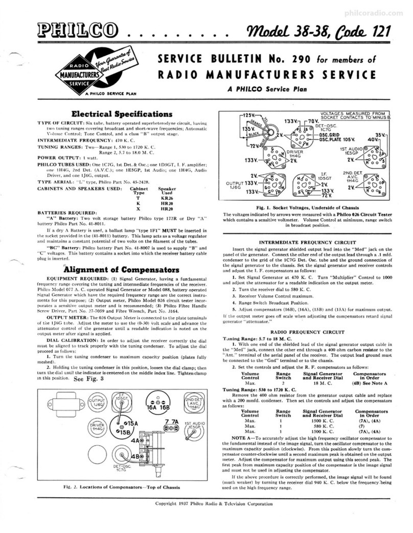
Fig. l. Underside View of Chassis showlnit Socket Voltages
The voltages indicated by the arrows were measured with a Philco 026 Circuit
Tester, which contains a sensitive voltmeter. Line voltage 115 A. C.-Volume
control minimum-Dial set at point where no signal is present....:......RangeSwitch
in broadcast position.
Automatic Tuning Mechanism
Service Data
Service data and a complete parts list for the Automatic Tuning
Mechanism of this receiver will be found in Service Bulletin 273.
When referring to bu,lletin 273, use the dial parts list for Model 37-10
as the same parts are used on Model 38-1. There are four automatic
dial parts, however, which differ from those shown in bulletin 273.
These parts are marked with an asterisk on page 3 of this bulletin.
Service Notes
For reference between illustrations, Parts List, and for replacement
of parts, the various diagrams in this bulletin are marked with
"circled numbers" indicating a particular part.
Physical views of the R. F. t_ransformers are shown on page 2.
Each transformer is marked with the corresponding schematic dia-
gram circled number. The connections of the R. F. transformer are
numbered to indicate the connecting points in th" circuit diagram
which are correspondingly marked.
The colors of the I. F. transformer leads are marked on the
schematic diagram.
Range switch lugs are marked with a letter and number-example
(A2)-indicating the connecting point in the circuit diagram. Each
range switch section is marked with a letter indicating the position
of the section from the rear of the chassis. Section "A" is used in
the oscillator circuit. Section "B" the "RF" circuit, and Section
"C" the antenna circuit.
The colors of the connections on the power transformer and speaker
unit are also marked on the schematic diagram.
Copyright 1937, Philco Radio & Television Corp0ration
philcoradio.com

Page2 PHILCO SERVICE BULLETIN
~
·-.ou.~1
~.
,.,;
~
0
,'
<
0
~·
..
:@'
g~~l D
~
~~@~~ll
~@+
oJ~I -1 i
@JroiLAMPS I j .15,-t. .15,.f. L /
' I I /
~ -- frl@}<@F~
"61·;A1 I}.!87
: A8 65 8
''J"-1. A9 64 ._ 69
· ; A10 BJ 610
,· A11 62 11
• f"ILAM[NT .•
_.._,..c,o
LETTERS INOICATC ~O S ITION or SWITCH WAFERS
f'AOM AC.AA or CHASSIS, (&OTTOM VIEW),
ALL RANG[ SWITCHES SHOWN IN POSITION No1 ( 1t"DC' ST) .
........,,...,, .........,...............
SOLID AA[A INDI CA TES "'"-'"" ur ~" ' '.,." n .. r .... .
- •• • -•- •-• • •••- •• ••r•
~"APJII.P,I ""II." '" "'''--••11.~FAONl or SWIT CH WAF ER
-·· ·----- - ---- ... ---··-
TA AN Sf'0A.M[AS SHOWN wr,., lrtUt.X :iW I IN '"-UNI
,'
c!_/
2,._.,,,e=·"i, ..~,,. R·fr,
. ·.~,,t..1·J,,,I::lt~~t_ 3 2 1
0/ 8 ?>LA O(
C--U,:- 5 •1A
~A,CK
(i) ANT r,,\ ANT /j\ ANT ',1' RF @2 Fl F 113'Fl r '19'OS C
~
OSC tf,\- ·osc.
--- -~ \.!.)A.ANC[2 \:.)A.ANG[ 3 \1._1./FIAN C.t 1 RANGE 2
~
\tVRAN'l _[ f _~
~
01R EC TI O N o r ROT A T IO N
rR0 1.1 REAR o r SWIT CM
Fig. 2. Schematic Diagram
Model 38-1, Code 121
)
, )
Of~
,/ / 1
,// T
,,•'
t_',,.
@
"t ~@)
~
1'2.4.n.. 33 .n. 19.n..
No. 293
i
~1@
:r~
rl'9
J~
"
I.F.=470 K.C.
)
philcoradio.com

No. 293
Replacement Parts
Model 38-1, Code 121
Schem. Pan
No. Dncriptlon No.
1 Antenna Transformer (Range 1)....... 32-2575
2 Antenna Transformer (Range 2). ... . . . 32-2576
3 Antenna Transformer (Range 3) .... . . . 32-2673
4 Compensator, Antenna (Range 3) . ..... 31-6160
5 Condenser (.05 iJ tubular) ............ 30-4519
8 Conderu.er (.05 µf-. 05 ,.r Bakelite) . . .. 3615DG
7 Resistor (51,000 ll, ½ watt) . . .... ... . . 33-351339
8 Tuning Condenser A88embly. . . . . . . .. . 30-2075
9 Resistor (100 ll, ½ watt) .. ... .. ...... 33-110339
10 Condenser (.05 µf, tubular) ........ .... 30-4020
11 R. F. Transform er (Range I) ... . . . .... 32-2379
12 R. F. Transformer (Range 2).. ...... .. 32-2382
13 R. F. Transform er (Range 3).. .. .. . . . . 32-2385
14 Condenser (5 ,.,.f mica) ... .. .... . .. . .. 30-1097
~:g~::ir..:~p~~t!rrange 3).. .. ... .. 31-6212
17 Condenser (.05 µf tubular) ...... . ..... 30-4519
18 Compensator, Osc. (Range l) ........ .. 31-6212
19 Osc. Transformer (Range 1). .. . .. . .... 32-2373
20 Osc. Transform er (Range 2).... , . .. . . . 32-2383
21 Osc.Transform er (Range 3) ... ... . . . . . 32-2386
22 Compensator, Range 1 series ...... . ... 31-6151
23 Condenser (1605 ,.,.f mica) . .. ...... . .. 31-6201
24 Resi•to r (700 ll, ½ wat t) ... .. .... . . . . . 33-170339
25 Condenser (.01 µf tubular) .. .. .. , . .... 30-447n
28 Condenser (110,.,.f mica) .. .. .. . • .. .. . 30-1031
27 Condenser (110 ,.,.r mica) ...... ...... . 30-1031
28 Resistor (99,000 ll, ½ watt) ... .. . . . . . . 33-399339
29 Resistor (85 ll, ½ watt). .. . ... .. . . . . . . 33--085339
30 Resistor (99,000 ll, ½ watt) ... . . . . . . . . 33-399339
31 Condenser (.3 ,.f Bakelite) . .. . . . • . . . . . 6287DG
32 Compensator (2 sections) .. .. .. .. .... . 31-6211
33 Condenser (250 ,.,.f mica) ....... . . . .. . 30-1032
34 Resistor (32,000 ll, ½ watt) ... . . , . . . . . 33-332339
35 Resistor (10,000 ll, ½ watt) ... ...... . . 33-310339
38 Condenser (4280,.,.f mica) .... .... 31-6202
37 1st I. F. Transform er................. 32-2741
38 2nd I. F. Transform er .. .. . . ..... .. . .. 32-2742
39 Condenser (110,.,.r - 110,.,.f Bakelite) . 8035DG
40 Resistor (51,000 ll, ½watt) ........... 33-351339
41 Resistor (330,000 ll, ½ watt) . . ..... .. . 33-433339
42 Condenser (.01 ,.f tubular). .. . . . . . . . . . 30-4479
43 Resistor (4.0 meg., ½ watt). . ... . . . . . . 33-540339
44 Resistor (4.0 meg., H watt). . ... .. . ... 33-!i40339
45 Resistor (1.0 meg., ½ wait) ... ........ 33-510339
48 Resistor (1.0 meg., ½ watt) . . ... . . . . . . 33-510339
47 Resistor (1.0 meg., ½ watt) ....... . ... 33-510339
48 Resistor (1.0 meg., ½ watt) ..... ... . .. 33-510339
49 Resistor (1,000 ll, ½ watt) .... . . . . .... 33-210339
50 Condenser (.1iJ tubular) ... ... ....... 30-4455
51 Condenser (110 ,.,.f mica) . ....... .. ... 30-1031
52 Condenser (1101'/'f mica) ... .. .. ... ... 30-1031
83 Condenser (.05,.f Bakelite) ..... . . .... 3615SG
54 Resistor (490,000 ll, ½ watt) ... .. . . . . . 33-449339
55 Resistor (490,000 ll, ½watt) ... ... .... 33-449339
56 Condenser (.15 i,f- .15 ,.f Bakelit e) . .. . 6287DG
57 Condenser (.015 µf tubular) . .. . . . . . . . . 30-4226
58 Resistor (240,000ll, ½ watt) .. ... . . .. . 33-424339
59 Condenser (.015 µf tubular) ..... . . .... 30-4226
80 Resistor (32,000 ll, ½ wat.t). .. .. . .. . . . 33-332339
81 Reaistor (25,000 ll, ½ watt) . . ... . . . . . . 33-325339
82 Resistor (09,000 ll, ½ watt) ... ........ 33-399339
83 Resistor (51,000 ll, ½ watt) ........ ... 33-351339
84 .VolumeContro l ................ ,. . 33-5233
85 Resistor (1.0 meg., ½ watt) . . .. . .. 33-510339
88 Resistor (20,000 ll, ½ watt) . . . . . .. 33-370339
87 Condenser (.I ,.r tubular) ... . . . . .. . 30-4455
88 Condenser (.006 µf tubular) .... . ...... 30-4445
89 Audio Shorting Switch (Part of Auto .
Tuner-See parts (6) and (16) Bulletin
273)
70 Reoiotor (490,000 ll, ½ watt) . . . .. .. 33-449339
71 Condenser (.I ,.r tubular) ... . . . . . •. 30-4499
72 Condenser (.05 i,f Bakelite). 3615SU
73 Condenser (.02 µf tubular). 30-4113
74 Resistor (1.0 meg., ½ watt) ........... 33-510339
75 Resistor, wire-wound (7,500 ll- 9,000 ll) 33-3320
LIit
Price
S0.70
.70
.70
.30
.20
,40
.20
,20
.20
.40
1.00
1.20
.20
.20
1.60
.70
.70
.40
.40
.20
.20
.20
.20
.20
.20
.20
.40
.26
.20
.20
.50
3.50
.26
.20
.20
.20
.20
.20
.20
.20
.20
.20
.20
.25
.20
.20
.35
.20
.20
.40
.20
.20
.20
.20
.20
.20
.20
.20
.20
.25
.20
.20
.20
.35
.20
.20
.65
PHILCO SERVICE BULLETIN
Schem. Pan
No. Deacrlptlon No.
76 Resistor (51,000 ll, 1 watt) .... . ..... .. 33-351439
n Electrolytic Condenser (4i,f-3 i,O . . . . 30-2243
78 Condenser (.1 ,.f tubular) .. ...... .. ... 30-4455
79 Resistor (330,000ll, ½ watt). ... . . . . . . 33-433399
80 Condenser (.1i,f tubular) .. ... ........ 30-4455 .
81 Resistor (70,000 ll, ½ watt) . . . .. . . . . . . 33-370339
82 Resistor (32,000 ll, ½ watt) . . .. . . . . . . 33-332339
83 Resistor (32,000 ll, ½ watt) . . .. . . . . . . 33-332339
84 Condenser (.05 µf tubular) ... . .. .. ... 30-4177
85 Resistor (330,000 ll, ½ watt) ... 33-433339
88 Condenser (.! i,f tubular) .. . . .. . .. .... 30-4455
87 Resistor (70,000 ll, ½ watt) . . . .. . . . . . . 3.3-370339
88 Condenser( .! ,.f tubular) ............ 30-4455
89 Input Transformer ..... . .. . . . . . .... .. 32-7671
90 Resistor (51,000ll, ½ watt) .... . ...... 33-351339
91 Condenser (.01 µf tubular) .. ..... .. .. . 30-4381
92 Output Tran sformer .... ............ . . 32-7914
93 Cone & Voice Coil A!'Belllbly(U28
Speaker) .. .. .. . .. .. .. .. . .. .. .. .. . 36-3799
94 Condenser (.OJ,.r tubular) ..... .. ... .. 30-4381
95 Resistor (5,!IOOll, wire-wound) . . . . . . . . 33-3282
96 Field & Pot ASRembly (U28 Speaker) .... 36-3162
97 Resistor, Thr ee Sections (1241l- 33 ll-
!9 ll) . . . .. .. .. .. .. .. 33-3319
11, Electrolytic Condenser (18,.o..... 30-2200
89 Choke ........ .. ..... 32-7115
100 Resistor (3,000 ll, ½ watt) .. .. . , . .. . . . 33-230339
List
Price
$0.20
1.50
.25
.20
.25
.20
.20
.20
.25
.20
.25
.20
.25
2.50
.20
.25
1.85
.25
.60
11.00
.50
1.40
1.80
.20
Fig. 3. Part Locations, Underside of Chassis
Schem. Part Lilt
No.
101
102
103
104
Deacrlptlon No. Price
Condenser (.25 µf tubular) . .. . . . . . . . . 30-4446 $0.26
Electrolytic TwoSections (Sµf-!O i,0 31).2201 1.76
Pilot Lamp .. . .. .. .. .. .. .. .. .. . .. .. . 34-2064 .09
Power Transformer (115 v. 50 to 60
cycles) ........ ........ ... ......... 32-7869
Power T1ansformer (115 v. 25 to 40
cycles) .... .. ............... : ... ... 32-7870
Power Transformer (115/230 v, 50 to
60 cycles) .. . .. .. .. . .. .. .. .. .. .. .. 32-7871
105 Tone Control. ..... ..... .. . . . .. .. ... 42-1268
108 Condenser (.015 i,f- .015 µf Bakelite) . 3793DG
107 A.F.C. Shorting Switch (Part of Auto.
Tun er-See part (8) Bulletin 273) 45-2330
108 A.F.C. Switch Manual ............ .. . 42'-126.9
109 Flood Lamp ............... .... ..... 34-~64
110 Wave Switch Complete .............. 42-1362
MODEL38-1
Automatic Tuni ng Mechanism Complete ... 38-9145
Brace (Automat.ic Mechanism) . .. . ...... 28-4119
Cable (Speaker). . . . . . . . 41-3329
Cable (Power) ....... ·. .. L-2183
Clip (Mtg . R. F. Coils) ..... . 28-5002
Coupling (Tuning Condenser) .......... . .. 31-1961
Coupling (Rang e Switch Shaft & Mask) .... 38-8693
Knob (Range Switch) .. ....... . . .. ....... 27-4326
Knob (Tuning) . ... . . . . . 27-4330
Knob (Vernier) .. .. . .. .................. . 27-4331
.75
.40
1.80
.09
3.00
Page3
Schtm. Pan LIii
No. D-lptlon No. Price
Knob (Tone, Volume) ................... 27-4332
Mtg . Rubber (Chasai8).. ...... . ......... . 27-4564
Mtg . Rubber (Rear of R. F. Unit) ..... .. .. . 27-4197
Mtg . Rubber (Front of R. F. Unit) .. , ... . . 27-4581
Pilot Lamp A..embly .... .... . ........ . .. . 38-9100
Shield (R. F. Unit) .. . ... ......... . ..... . . 38-8969
Shield Base (Round): . .. .. .. .. .. •.. .. . . . . 8004
Shield Base. .. .. .. .. .. .. .. .. . .. .. .. .. . . . 28-2725
Shield (Tube) (Square) .. ... . . .. . . . . . .... . 28-2726
Shield (6U7G Tube) ........... . . .... . .. . . 28-5031
Shield (Round) ........ . ............ ... . . 8005
Socket (6 prong) .... .... .... ............. 27-6086
Socket (7 prong) (6F6G Tubes) .. .. .. . ..... 27-6057
Socket (7 prong).. .. .. .. .. .. .. . . .. .. .. .. . 27-6087
Speaker (U-28) ....... .... . ............. . 11&-1361
Support (Rear of R. F. Unit) ........ . .... . '38-8923
Terminal Panel (Ant.)CABINti'i>ARTs·.. 38-8746
Bezel A880mbly.·.. .. . .. .. .. . . . .. .. .. .. .. . 38-8833
Cover (Backof Cabinet) .. . .. .. .. .. .. .. .. . 27-8865
AUTOMATICTUNINGMECHANISM
•cove r (Handle) .... .. .. .. . .. .. .. . . .. .. . 28-5092
•Dial .. .. .. .. .. .. .. .. .. .. .. .. .. .. .. .. .. . 27-5358
•Dial Screen Holder . ............. . . . ..... 31-2053
•Escutcheon Assembly (Station tabs) . . . 45-2472
•These Automstic Tuning Mechanism parts differ from those
shown in Service Bulletin 273.
The Genuine PHILCO Replacement Parts listed above must be used l , fain the Accurate Balanced Performance built into this Philco Mode {
philcoradio.com

Page4 PHILCO SERVICE BULLETIN No. 293
Alignment of Compensators
EQUIPMENT REQUIRED: (1) Si_gnal Generator, having a fundamental
frequency range covering the intermediate and tuning frequencies of the receiver.
Philco Model 077 Signal Generator which has a fundamental frequency range from
115 to 36000 K.C. is the correct instrument for this purpose; (2) Output Meter,
Philco Model 026 Circuit Tester incorporates a sensitive output meter and is
recommended; (3) Philco Fiber Handle·Screw Driver, part number 27-7059 and
Fibre Wrench, part number 3164 .
OUTPUT METER: The 026 Output M<,ter is connected to the plate and
cathode terminals of one of the 6F6G tubes . Adjust the meter to use .the (0-30)
volt scale and advance the attenuator control of the generator until a readable
indication is noted on the output meter after signal is applied to stage being adjusted .
DIAL CALIBRATION : In order to adjust the compensator• of this receiver
conectly, the dial must be aligned to track properly with the tuning condenser.
To do this proceed as follows:
1. Loosen the set screws on the shaft coupling of the tuning condenser . Then
tutn the tuning condenser until the plates are in the maximum capacity position.
Now turn the dial until the glowi ng beam indicator is on .the INDEX LINE at
the low frequenc y end of Range 2. See Fig . 4. With dial and tuning condenser in
this position tighten set screws.
2. Turn the tuning condenser control until the indicator is on the 2.2 M . C .
mark .
3. With the dial in this position, loosen the shaft coupling set screws. Then
turn the dial until the indicator is again on the INDEX LINE. Tighten the set
screws in this position.
NOTE: Be careful when turning the dial that the position of the tuning
condenser is not disturbed .
INTERMEDIATE FREQUENCY CIRCUIT
A. Set the receiv .er and signal generator controls as follows:
1. Range Switch (Broadcast Position) ·
2. Volume Control (Maximum)
3. Magnetic Tuning Switch "Off"
4. Tone Control First Position
5. Signal Generator Dial 470 K.C.
B. Connect the •ignal generator output cable through a .I mfd . condenser
to the grid of the 6A8G Det. Osc. tube and connect the cableground to the re•
ceiver chassis. Set the generator "attenuator" for maximum output. Adjust the I.
F. Compensator• as follows:
1. Turn compensator (37C) in until the output meter reading decreases
almost to zero.
2. Now adjust the compensators, (37B) and (37A), for maximum output;
then readjust (37C) for maximum output.
3. Turn compensator (38C) in about
three turns; then adjust compensators (38B)
and (38A) for maximum output. The
adjustment of compensator 38C is given
in the " Magnetic Tuning Circuit Adjust-
ments " below .
RADIO FREQUENCY CIRCUIT
1. Set the controls as given under
"Intermediate Frequency Circuit" 1 to 4
and set the range switch, signal generator
and receivet dials as given under the adjust-
ments of each tuning range in the following
procedure .
Connect the Signal Generator output
cable into the "Med" jack of the generator
panel and connect the other end through a
.1 mfd . condenser to the " Red" terminal of
the receiver aerial panel (rear of chassis).
The ground connection of the cable should
be connected to the "Blk" terminal.
2. Adjust the "R. F ." compensators
for maximum output .as follows:
Tuntna Ranae: 530 to 1720 K. C.
TUNE FORE
SLOWLY A
I.IIUS IU
TUIIIE LO"
_.1-----PAltlS At
NUM&llt
l'i TH[
£R NU~
INDEX LINE
Fla. 4. Dial Calibration
Ranae Switch
Position
1
Stana! Generator
and Recelnr Dial
1550 K. C.
Compen&ators
In Order
(18), (8B), and (8A)
I 580 K. C.
1550 K. C.
Tuntna Ranae 2.3 to 7.4 M . C.
Ranae Switch Stanal Generator
Poeltlon and Receiver Dial
2 6.0 M. C.
(22), Roll Tuntna Condenser . See
Note B.
(18), (8B), (8A)
Compen&atora
In Order
(32)
0 32
@
,,,,-._
~;:~TJ
0 @
,,,,__32 A
OUTPUT
~
0
0
@15 38~CeoTTOM (AV?:)
v.,
~~~
-
'"38Awm-c
2ND.DET. 38BTOP
!ST.AUDIO fPHAStl
~
INV[RT[R
~
Fla . 5. Compen&ator Locations
Tunlna Ranae:
Ranae Switch
Position
3
3
7.35 to 22.0 M. C .
Stana! Generator
and Receiver Dial
18.0 M. C.
18.0 M . C.
Compen&ators
In Order
(32A), (15), (4)
Roll tuntna condensers when adjust-
Ina (15) and (4). See Note B, check
lmaae at 17.060. See Note A.
(32A)
MAGNETIC TUNING CIRCUIT ADJUSTMENTS
1. Set the Magnetic Tuning switch in the "out" position .
2. Turn the signal generator indicator to 1000 K. C. and adjust the "Allen
uator" control for a weak signal.
3. Adjust volume control for a readable indication on the output met« .
4. Now tune the receiver dial for maximum output at 1000 K. C. The dial
must be tuned very accurately to the 1000 K. C. signal in order to make the fol-
lowing adjustment correctly.
5. Turn the Magnetic Tuning Switch "In" and adjust compensator (38C)
for maximum output.
The above adjustments are now checked for accuracy as follows:
FREQUENCY TEST:
With the 1000 K . C. signal tuned for maximum output turn the Magnetic
Tuning control back and forth; that is, from the "out" to "in" position . The reading
of the output meter should not change in either position. If the output meter
reading changes, the above magnetic tuning circuit adjustments ,hould be repeated .
A further check on the magnetic tuning adjustment is to very carefully tune
in a broadcasting station and turn the switch from the "out" to the "in " position .
With the switch in either position, the tone of the station being received should
not change. If a change of tone or hiss develops repeat the above Magnetic Tuning
Adjustments .
SENSITIVITY TEST :
l . To check the magnetic tuning circuit for sensitivity, turn the magnetic
tuning switch to the "off" position, and tune in the 1000 K. C. signal. Then adjust
the "attenuator" control of the signal generator for a good audible signal. Approxi-
mately 20 volts on the output meter .
2. Now detune the signal (first above and then below the 1000 K. C. mark
to a point at which the signal is weakly heard . At each J>Qintturn the magnetic
tuning control "on". When the control is turned on the signal should return to
normal output strength . If the magnetic tuning circuit does not pull the signal
into resonance, the compensator (38C) should be carefully readjusted .
NOTE "A"-To accurately adjust the high frequency oscillator compensator
to the fundamental instead of the image signal, turn the oscillator compensator
to the maximum capacity position (clockwise). From this position slowly turn tfie
compensator counter-clockwise until a second maximum peak is obtained on the
output meter . Adjust the compensator for maximum output using this second peak.
The first peak from maximum capacity position of the compensator is the image
signal and must not be used in adjusting the compensator .
If the above procedure is correctly performed, the image signal will be found
(much weaker) by turning the receiver dial 940 K. C. below the frequency being
used on any high frequency range .
NOTE "B"-When adjusting the low frequency compensator of Range One
(Broadcast) or the antenna and R . F . compensators of the high frequency tuning
ranges; the receiver Tuning Condenser must be adjusted (rolled) as follows: First
tune the compensator for maximum output, then vary the tuning condenser of
the receiver for maximum output about the frequency dial mark. Now turn the
compensator slightly to the right or left and vary the receiver tuning condenser
ior maximum output. If the out reading increases, turn the compensator in the
same direction a trifle more, and again vary the tuning condenser for maximum
output . If the output decreases , set the compensator in the oppo,ite direction.
This procedure of first setting the compensat or and then varying the tuning
condenser is continued until there is no further gain in output reading . ,..--...,
August 1937
PHILCO RADIO AND TELEVISION CORPORATION
Parts and Service Division
Philadelphia, Pa. Printed in U. S. A.
philcoradio.com
Other manuals for 121
8
This manual suits for next models
1
Other Philco Radio manuals

Philco
Philco 37-116 User manual

Philco
Philco 80 User manual

Philco
Philco 121 User manual

Philco
Philco 37-650 User manual

Philco
Philco D-592 User manual

Philco
Philco 37-660 User manual

Philco
Philco 77 User manual

Philco
Philco PHOTOFACT 49-1150 User manual

Philco
Philco 121 User manual

Philco
Philco 66 User manual
Popular Radio manuals by other brands

Teufel
Teufel Radio 3sixty Technical description and user manual

MFJ
MFJ MFJ-1046 instruction manual

Meteor Communications Corporation
Meteor Communications Corporation MCC-545C Operation and maintenance

Sandstrom
Sandstrom S2RADB12E instruction manual

Scansonic
Scansonic I101 BT user manual

MAJORITY
MAJORITY PARKSIDE COLOUR user manual