manuals.online logo
Brands
  1. Home
  2. •
  3. Brands
  4. •
  5. Philco
  6. •
  7. Radio
  8. •
  9. Philco D-592 User manual

Philco D-592 User manual

This manual suits for next models

7

Other Philco Radio manuals

Philco 37-620 User manual

Philco

Philco 37-620 User manual

Philco 121 User manual

Philco

Philco 121 User manual

Philco 37-116 User manual

Philco

Philco 37-116 User manual

Philco 118 User manual

Philco

Philco 118 User manual

Philco 37-670 User manual

Philco

Philco 37-670 User manual

Philco 37-630 User manual

Philco

Philco 37-630 User manual

Philco 15 Series Reference manual

Philco

Philco 15 Series Reference manual

Philco 37-60 User manual

Philco

Philco 37-60 User manual

Philco PRR1005BT User manual

Philco

Philco PRR1005BT User manual

Philco 37-675 User manual

Philco

Philco 37-675 User manual

Philco 200 User manual

Philco

Philco 200 User manual

Philco 96 User manual

Philco

Philco 96 User manual

Philco 16 Reference manual

Philco

Philco 16 Reference manual

Philco 144 User manual

Philco

Philco 144 User manual

Philco 116 User manual

Philco

Philco 116 User manual

Philco 80 User manual

Philco

Philco 80 User manual

Philco 623 User manual

Philco

Philco 623 User manual

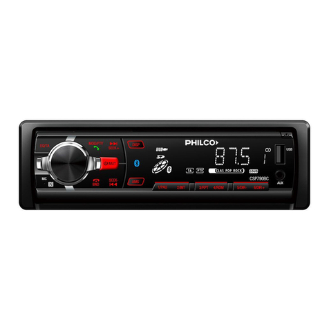
Philco CSP790BC User manual

Philco

Philco CSP790BC User manual

Philco 121 User manual

Philco

Philco 121 User manual

Philco 77 User manual

Philco

Philco 77 User manual

Philco 29 User manual

Philco

Philco 29 User manual

Philco 121 User manual

Philco

Philco 121 User manual

Philco 121 User manual

Philco

Philco 121 User manual

Philco 121 User manual

Philco

Philco 121 User manual

Popular Radio manuals by other brands

Grundig G6 AVIATOR owner's manual

Grundig

Grundig G6 AVIATOR owner's manual

Makita DMR114 instruction manual

Makita

Makita DMR114 instruction manual

PURE Move R3 manual

PURE

PURE Move R3 manual

Motorola CP040 Detailed service manual

Motorola

Motorola CP040 Detailed service manual

Bosch GPB18V-5C Operating/safety instructions

Bosch

Bosch GPB18V-5C Operating/safety instructions

Ocean Digital WR-230 user manual

Ocean Digital

Ocean Digital WR-230 user manual

Realistic TRC-457 owner's manual

Realistic

Realistic TRC-457 owner's manual

Uniden AX 144 owner's manual

Uniden

Uniden AX 144 owner's manual

SIGNIFY EA2173 instruction manual

SIGNIFY

SIGNIFY EA2173 instruction manual

auna multimedia 10026443 user manual

auna multimedia

auna multimedia 10026443 user manual

GME TX680 instruction manual

GME

GME TX680 instruction manual

Motorola MTM5 00 Series Basic service manual

Motorola

Motorola MTM5 00 Series Basic service manual

Tivoli Audio ONE+ owner's manual

Tivoli Audio

Tivoli Audio ONE+ owner's manual

Sirius Satellite Radio SDVK1 installation guide

Sirius Satellite Radio

Sirius Satellite Radio SDVK1 installation guide

Sirius XM RAdio EDGE user guide

Sirius XM RAdio

Sirius XM RAdio EDGE user guide

Trevi XF 100 user guide

Trevi

Trevi XF 100 user guide

EisSound KBSound iSelect user manual

EisSound

EisSound KBSound iSelect user manual

Kirisun DM588-02 user manual

Kirisun

Kirisun DM588-02 user manual

manuals.online logo
manuals.online logoBrands
  • About & Mission
  • Contact us
  • Privacy Policy
  • Terms and Conditions

Copyright 2025 Manuals.Online. All Rights Reserved.

le
TELEVISION •
RADIO-
PHONOGRAPH •
RADIO
PHILCO
HOME
RADIO
MODELS
D-592, D-593, D-595, D-598,
D-727,
D-728,
D-730
and
D-736
PHILCO
MODEL
D-592
PHILCO
MODEL
D-727
çe
e
- e
‘\,
PHILCO
MODEL
D-593
PHILCO
MODEL
D-595
zrt“.
1/1
MI
.mroxe"
npinmme
nrnme"
mgeN/tr
5"n
à
et
,/ 44 o L
?"
rIrre.1
P
PHILCO
MODEL
D-598
PHILCO
MODEL
D-728
PHILCO
MODEL
D-730
PHILCO
MODEL
r -
736
HO
ADI
SPECIFICATIONS
Cabinet
D-552,
D-593,
D.595,
D-727,
D-728
and
D-730 —
molded
plastic;
D-598
and
D-736 —
wood
table
model.
Circuit
Four
tube
superheterodyne
(plus
rectifier).
Frequency
Ranee
540
KC
to
1620
KC.
Audio
Output
1
Watt
Operating
Voltage .
D-592, D-593,
D-595
and
D-598-105
to
120
volts,
AC
or
DC;
D-727,
D-728,
D-
730
and
D-736-105
to
120
volts
AC
only.
Power
Consumption
30
Watts
Aerial
Se1f
Contained
Magnacore
Intermediate
Frequency
455
KC
Philco
Tubes
128E6
Converter.
Oscillator,
12BA6
I-
F
Ampli-
fier.
12AV6
Detector —
1st
Audio,
35C5
Audio
Output
and
35W4
Rectifier.
Clock
Features
D-727 —
Sessions
movement,
radio
alarm.
D-728 —
Sessions
movement,
radio
alarm.
D-730 —
Sessions
movement,
radio
and
buzzer
alarm.
D-736 —
Sessions
or
Tele-
chron (
C995)
movement,
ra
dio
and
buzz
alarm.
Pilot
Lamp
Model
D-598
employs
a
neon
lamp
as
an
off
on
indicator.
Phono.
Input
Model
D-598
incor-
porates
a
phono
-
input
jack,
a
variable tone
control
and
a -
radio-phono"
switch.
Copyright,
1955,
PHILCO
CORPOHATION
Reproducticn
of
any
material within
this
publication
is
prohibited
without
th?
written
consent
of
the
copyright
owner.
PHILCO
CORPOPATION.
Pogo
Two
PHILCO
HOME
RADIO
SERVICE
MANUAL
ALIGNMENT
PROCEDURE
RADIO
CONTROLS —
Set
volume
control
to
maximum.
Set
tun-
ing
control
as
indicated
in
chart.
OUTPUT
METER -
Connect
across
voice-
coil
terminals.
SIGNAL
GENERATOR —
Connect
generator
and
set
frequency
as
indicated
in
chart.
Use
modulated
output.
OUTPUT
LEVEL —
During
alignment,
adjust
signal-
generator
out-
put
to
hold
output-
meter
reading
below .
5
volts.
ALIGNMENT
CHART
STEP
SIGNAL
GENERATOR
RADIO
ADJUST
DIAL
CONNECTION
TO
RADIO
SETTING
DIAL
SETTING
SPECIAL
INSTRUCTIONS
1
Ground
lead
to
B —;
output
lead
455
KC
through
a .
1
mf.
condenser
to
grid
(pin
7)
of
12BE6.
Tuning
gang
fully
open.
Adjust
tuning
cores,
in
order
given,
for,
maximum
output.
TC1
and
TC3
are
located
at
top
of
transformers.
TC4-2nd
i-f
sec.
TC3-2nd
i-f
pri.
TC2-1st
i-f
sec.
TC1-1st
i-f
pri.
2
Radiating
loop (
See
note
below).
1620
KC
1620
KC •
Adjust
trimmer
for
maximum
output.
CI-B--osc.
3
Some
as
Step
2.
1500
KC
1500
KC
Adjust
trimmer
for
maximum
output.
Cl
-
A--
aerial
NOTE:
Make
up
a
6-8
turn,
6
inch
diameter
loop
from
insulated
wire,
connect
to
signal-
generator
leads,
and
place
near
radio
loop.
For
proper
adjustment
of
the
oscillator
trimmer,
fully
open
the
tuning
gang
and
insert a .
006
inch
non-metallic
shim
between
the
heel
of
the
rotor
and
the
top
of
the
stator
plates.
Close
the
tuning
gang
sufficiently
to
hold
the
shim
in
place,
and
then
remove
the
shins
without
disturbing
the
gang
setting.
Composite
Photo
of
Printed
Panel
Showing
Parts
Layout
PHILCO
HOME
RADIO
SERVICE
MANUAL
Page
Three
REPLACEMENT
PARTS
LIST
Ref.
Sym.
CI
C2
C3
C4
C5
C6
C7
C8
C9
C10
Cl'
C12
CI3
C14
Ji
LAI
LS1
PL
RI
R2
R3
R4
R5
R6
R7
118
R9
R10
R11
R12
1113
1114
R15
SI
S2
Ti
T2
WI
Z1
Z2
Description
Service
Part No.
Condenser,
tuning
gang
31-2780-2
Condenser,
tuning
gang.
D-598
only
31-2780-5
Condenser,
neutralization,
9
mmf,
ceramic
30-1251-5
Condenser,
oscillator
grid,
47
mmf,
ceramic
30-1230-4
Condenser,
tone
compensation, .
01
mid,
disc
30-1238-2
Condenser,
electrolytic,
3
section
30-2585-5
Condenser,
line
by-pass, .
047
mid,
moulded
30-4650-45
Condenser-
resistor
network
30-6006
Condenser,
AVC
by-pass, .
G47
mid,
moulded
30-4650-45
Condenser,
audio
coupling, .
01
mid,
moulded,
D-598
only
30-4650-41
Condenser,
tone
control,
1
mid,
moulded,
D-598
only
30-4650-47
Condenser,
tone
control, .
0082
mid.
D-598
only
30-4651-18
Condenser,
tone
control, .
1
mid,
moulded,
D-598
only
30-4650-47
Condenser,
tone
compensation, .
01
mid,
moulded
D-598
only
30-4650-41
Condenser,
phono.
jack
isolation, .
047
mid,
moulded.
D-598
only
30-4650-45
Jack,
phono.
connector.
D-598
only
27-6186
Antenna,
magnecore.
and
supprrt
assembly
76-9228-3
Speaker,
D-592,
D-593,
D-595,
D-727
and
D-728
36-1654
Speaker,
D-598 (
2
used)
36-1663-6
Speaker,
D-730 .
36-1660
Speaker,
D-736
36-1655
Pilot
lamp,
neon,
D-598
only (
Type
NE51)
34-2482-1
Resistor,
oscillator
grid
return,
22,000
ohms
66-3228340
Resistor,
I-
F
cathode
bias,
68
ohms
66-0688340
Resistor,
AVC
filter,
2.2
megohms
66-5228340
Volume
Control,
500,000
ohms,
D-592,
D-593
and
D-595
33-5575-4
Volume
Control,
1
megohm,
D-598
33-5566-73
Volume
Control,
500,000
ohms,
Er-
727,
D-728,
D-730
and
D-736
33-5575-3
Resistor,
output
cathode
bias,
150
ohms
66-1158340
Resistor,
B •
filter,
2200
ohms
66-2228340
Resistor,
B •
filter,
3300
ohms
66-2338340
Resistor,
filament
current
limiting,
100
ohms,
D-592, D-593,
D-598
33-1360-6
Resistor,
filament
current
limiting,
100
ohms,
D-595,
D-727. D-728,
D-730
and
D-736
33-1343-3
Resistor,
diode
load,
390,000
ohms,
D-598
only
66-4398340
Resistor,
tone,
560
ohms,
D-598
only
66-1568340
Tone
control,
250,000
ohms,
D-598
only
33-5581
Resistor,
tone,
1800
ohms,
D-598
only
66-2188340
Resistor,
tone,
18,000
ohms,
D-598
only
66-3188340
Resistor,
tone
compensation,
output
plate,
4700
ohms,
D-598
only
66-2478340
Resistor,
current
limiting,
neon
bulb.
150,000
ohms,
D-598
only
66-4158340
Switch,
on-
off,
D-592, D-593,
D-595
and
D-598
Part
of
R4
Switch,
D-727, D-728,
D-730
and
D-736
Part
of
Clock
Assy.
Switch,
radio
-
phono.,
D-598
only
Part
of
R11
Transformer,
oscillator
32-4582-5
Transformer,
audio
output ..
32-8384-2
Transformer,
audio
output,
D-598
only
32-8729
Line
cord
41-3865
Transformer,
1st
I-
I-
32-4583-5
Transformer,
2nd
I-
F
32-4583-6
CABINET
PARTS
Service
Description
Port
No.
Model
D-592
Cabinet,
Black .......
11063-8
Back
and
line
cord
76-9186
Dial
scale
Knob,
tuning
54-6156-12
Knob,
volume
Model
D-593
11063-6
Grille
28-10246-3
Knob,
tuning
54-6150-8
Knob,
volume
54-6159-11
Cabinet,
Cherry ..
11063-9
Grille ... .. .
28-10246-2
Knob,
tuning
54-6156-12
Knob,
volume ................
54-6159-14
Cabinet,
Lustre
Ivory
Grille .
28-10246-4
Knob,
tuning
54-6156-9
Knob,
volume
54-6159-12
Back
and
line
cord
assy.
Dial
scale
Model
D-595
Cabinet,
Amazon
Green
11148-1
Model
D-736
Cabinet,
Mahogany
11152
Back
54-9658-1
Bezel,
clock
28-10363-2
Bezel,
radio
28-10364-4
Clock
41-2057-2
Clock,
crystal .
54-6196-1
Clock,
face
28-109044
Clock,
knobs
(
2)
54-6096-3
Knobs,
tuning
and
volume
(
2) .
54-6224
Parts
Layout
on
Control
Panel —
Model
C9
R9
SI
MISCELLANEOUS
PARTS
Service
Description
Part No.
Printed
Wire
Panel
54-6182-1
Contact,
male,
AC
interlock (
2
used) .
L3520FEI8
Fastener,
wire
mounting
28-2669-3
Socket,
tube,
12BE6
and
12BA6 . .
27-6296-6
Socket,
tube,
35W4
and
35C5 .
27-6309-1
Socket,
tube,
12AV6 .
27-6296-16
Socket
Assy.,
neon
indicator.
D.598
only
27-6233-6
Grille
background
54-6222
Knob,
tuning
54-6220-1
Knob,
volume
54-6035-3
Cabinet,
Calypso
Red
11148-3
Grille
54-6219
Grille
background .
54-6222-1
Knob,
tuning
54-6220-2
Knob,
volume
54-e35-5
Cabinet,
Lustre
Ivory
e
Grille
background .
Knob,
volume
Back
and
line
cord
assy.
Model
D-598
Cabinet,
Wood,
Mahogany
Back, cabinet
Backplate,
scale
Dial
scale
Feet (
4)
Jewel
Clip,
jewel
mounting
Knob,
pointer
Knob,
tuning
Knob,
volume
and
tone (
2) .
Model
D-727
Cabinet,
black
Back
and
line
cord
assy.
Clock,
crystal
Clock
face
Clock,
knobs
(
2)
Clock,
trim
Knob,
tuning
Knob,
volume
Model
D-728
Cabinet,
Bermuda
Pink
Grille ..... ............
Knob,
volume
Grille
Knob,
tuning
Cabinet,
Lustre
Ivory
Grille
Knob,
volume
B
ack
and
line
cord
assy. ......................
Clock
Clock,
crystal ... ........................... ...
Clock,
face
Clock,
knobs (
2)
Clock,
trim
Model
D-730
Cabinet,
Bolero
Red
Back . . ..... .......
Knobs,
tuning
and
volume (
2)
.
Cabinet,
Lustre
Ivory
Back
Clock
face (
41-204807
clock)
Knobs,
tuning
and
volume
(
2)
Cabinet,
Mayan
Turquoise
Back
Knobs,
tuning
and
volume (
2) .
Bezel,
clock
Bezel,
radio
Clock
Clock,
crystal
Cock,
face
Clock,
knobs (
2)
.... ... •
11148-2
54-6219-1
54-6222-1
54-6035-4
78-9866
11162
76-9992
28-11096
54-6244
W2I90
54-4304-4
56-3545-6
54-6240
54-6230-2
54-4773-28
11062-10
76-5946
54-5208
28-10904-2
54-6096-3
28-10195-1
54-6156-13
54-4773-23
11062-9
54-6193-2
54-6093-7
54-6035-1
11062-7
54-6193
54-6147-17
54-4773-16
11062-8
54-6193-1
54-6147-18
54-4773-17
76-9946
41-2057-3
54-5208
28-10904-2
54-6096-3
28-10195-3
11076-12
54-6163-7
54-6093-9
11076-11
54-6163-6
41-2048-7
28-10034-5
54-8093-8
11076-13
54-6163-8
54-6093-10
28-10363-3
28-10364-5
41-2057-1
54-6169-1
28-10904-1
54
6096-3
Page
Four
PHILCO
HOME
RADIO
SERVICE
MANUAL
LAI
2.
tuN.NG
CO4DERSER
I2444
I
116V
I
I
e _ J
6.50
34
C2
SWAT
000
ARV
5
52
••11
S0
;2.0007t
R 3
2.2
MED
6
•
220121.
5
AUV
*700
R•
•
am
.
.
005mr
eiC
,
25µµ1
=1;5
L111
,
3515
OV
5.4V
roo,
e
R5,
.5011
R7
3.30
SSA,
T.
AI
.
Ce
047
RO
• 3 4
1oon •
33C5
1211. I2DES
12•RA
SURGE
LIMITING
RES
NOTES
•
ALL
COMPONENTS
MARKED
RITO
ASTERISK
ARE
CONTAINED
IN
I
UNIT.
C7
ALL
VOLTAGES
MEASURED
RITO
A
20.000
OHMS-
PER-
vOLT
VO
TTTTT
E•
BETWEEN
POINTS
INDICATED
MOD
e
MINUS.
AT
A
LINE
VOLTAGE
OF
117v
AC
OSCILLATOR
GRID
VOLTAGE
MEASURED
ACROSS
RI
WITH •
100.000
O.
ISOLATING
RESISTOR
IN
SERIES
70TH
METER
ALL
RESISTOR
VALVES
ARE
IN
OTHAS
AND
ALL
CONDENSER
VALUES
IN
tallf
UNLESS
OTHERWISE
INDICATED
®
INDICATES
LESS
THAN
I
0.04
X
INDICATES
CLOCK
SOCKET
CONNECTIONS
SCHEMATIC
OF
MODELS
D-592,
D-
593 AND
D-595
FOR
MODELS
D-727,
D-728,
0-730
AND
D-736
REFER
TO
CLOCK
CIRCUIT
IN
INSERT
-
L..
CCHEM..
.24511
r—
— — —
—
1 r—
Et
0 .
047,s1
DO »
CS
QUO .
2111451
.
11
S.
MOM
•
ALL (
0...LEN'S ...
ED ••••
LISTEIEISS
ARE
COSTAD
N
r•
•
LOL/445 •
20,000
04.14-01/. •
OL.T
TER
SPT,.NPfl5,
LLO,A
,
E0 •...
At
A -
ME
TTTTT
De
01
11
.
AC
0"(..LALOR ...
ID ',
CAGE ...
ED
ACROSS
01
n.
.5.1
,
00
SE.S
wow
«
TER
AL.
EMS
,.
.•,,
LES
AILII
01
0.5
AND
ALL
CONDOLSIA
LA...(1.
IF4
O,CATIS
LlLS
'
ROL
X •
NOCATES
CLOE•
SCR.
,
COLLNECLONS
•PIONO
35C5
T2
PR-
2905-10-55
SCHEMAT.0
OF
MODEL
Printed
in
U.S.A.
PHILCO
PORTABLE
RADIO
MODELS
D-664
AND
D-665,
CODE
124
AND
D-665,
CODE
126
MODEL
D-665
ALIGNMENT
PROCEDURE
General —
Allow
set
and
test
equipment
to
warm
up
for
fifteen
minutes
before
starting
the
alignment.
Dial
Indicator —
Before
alignment,
the
chaI
knob
should
be
set
as
follows:
with
the
condenser
gang
plates
fully
meshed,
the
first
knob
marking (
past
the
550
KC
point)
should be
in line
with
the
gold
spot.
Output
Indicator —
Connect
a
1000-
ohms-
per-
volt
a-
c
voltmeter
or
an
oscilloscope
across
the
voice-
coil
terminals.
Signal
Generator —
Use
an
AM
r-
f
signal
generator.
Connect
the
ground
lead
to
B—,
and
connect
the
output
lead
as
indicated
in
the
alignment
chart.
Output
Level —
Attenuate
the
signal-
generator
output
throughout
the
alignment
so
as
to
maintain
the
output
below .
4
volts.
Radio
Controls —
Set
the
volume
control
to
maximum.
Set
the
tuning
control
as
indicated
in
the
alignment
chart.
It
is
recom-
mended
that
a-
c
power
be
used
when
aligning
the
radio.
ALIGNMENT
CHART
MODEL
D-664
HO
RADIO
111111
SPECIFICATIONS
Circuit —
Four
tube
superheterodyne
(plus
selenium
rectifier).
Audio
Output —
AC
or
DC
operation —
150
milliwatts.
Battery
operation —
75
milliwatts.
Supply
Voltage —
117
volts,
AC
or
DC.
3.0
volt "
A"
supply
and
75
volt "
B"
battery.
Power
Consumption —
AC
or
DC
opera-
tion,
11
watts;
battery
operation,
10
MA
from "
B", 130
MA
from "
A".
Antenna —
Magnecor,
high-
impedance
loop.
Intermediate
Frequency —
455
KC.
Philco
Tubes —
1R5
Converter,
1U4
I-
F
amplifier,
1S5
detector -
A.V.C. -
1
audio,
3V4
output.
Battery
Types —
P-144 "
B"
battery, (
2)
P-77 "
A"
batteries.
STEP
SIGNAL
GENERATOR
DIAL
SETTING
Tuning
gang
fully
open.
RADIO
ADJUST
CONNECTION
TO
RADIO
DIAL
SETTING
SPECIAL
INSTRUCTIONS
I
Connect
signal
generator
through
a
.1
mfd
condenser
to
pin
6 ( converter
grid)
of
1125
455
kc.
Adjust
for
maximum
der
given.
output
in
or-
TC4-2nd
I-
F
see.
TC3—Ist
I-
F
sec. (
top
Z1
TC2-1st
I-
F
pri.
(
bot
Z1)
2
Use
radiating
loop (
See
note
one
below).
1620
kc.
1620
kc. (
See
note
2
below). Adjust
for
maximum.
C1B—osc.
trimmer
3
Same
as
step
2.
1400
kc.
1400
kc. (
Tune
for
signal.)
Adjust
for
max
i
mum.
CI
A—
ant.
trimmer
4
Same
as
step
2.
600
kc.
600
kc. (
Tune
for
signal.)
Adjust
for
maximum
tuning
gang
while
adjustment.
output.
making
Rock
this
TC-1—Osc,
core
5
Repeat
steps
2,
3,
and
4
until
no
further
improvement
is
noted.
.-..",
,
..__ . . ... . .
NOTE
2:
-
urn,
0
inch
diameter
loop
made
up
of
insulated
wire.
Connect
to
generator
terminals,
and
place
about
one
foot
from
radio
loop.
The
tuning
condenser
can
be
set to
the
proper frequency
for
the
oscillator
adjustment
as
follows:
Fully
open
the
tuning
gang
and
insert
a .
006
non-metallic
shim
between
the
heel of
the
rotor
and
the
top
of
the
stator
plates.
Close
the
gang
sufficiently
to
hold the
shim
in
place,
and
then
remove
the
shim
without
disturbing
the
gang
setting.
es
o
o
o
tes
Copyright,
1955,
PHILCO
CORPORATION
Reproduction
of
any
material
within
this
publication
is
prohibited
without
the
written
consent
of
the
copyright
owner,
PHILCO
CORPORATION
TO
VOL
CONT
Re
AI
L
Cl2
RI7
A+
SWITCH
(
SI)
SIDE
OF +
LOW
SIDE
VOL
CONT
RB
RI5
RI4
S2
A—
TO
ON
OFF
e
SWITCH
SI
°-
VOL
CONT
ARM
R8
C9
RI3
R9
I
U5
or
I
S5
CS
Z2
CI3
ANT
SECTION
OF
GANG
CI
RED
0
T (
T2)
LEAD
C6
IU4
Z I
LAI
R6
RI?
CIO
C4
TI
C5
RI9
p 3
3V4
B_
Rh
RIO
C I I
R41
R7
RI6
R5
C2
A C
LINE
BLUE
OT (
T2)
RIB
LEAD
FROM
ON
OFF
SWITCH,SI
BASE
VIEW
CIB
CIA
C3
RI
IR
5
R2
OSC
SECTION
OF
GANG
CI
CR
I
AC LINE
REPLACEMENT
PARTS
LIST
CABINET PARTS —
D-664,
Code
124
Reference
Service
Symbol
Description
Part
No.
CI
Condenser,
tuning
gang,
D-664
and
D-665,
Code
124
31-2735-9
D-665,
Code
126
31-2735-6
C2
Condenser,
temperature
compensation,
7.5
mmf
30-1224-13
C3
Condenser,
dual
by-pass, .
004/.004
mfd
30-1239
C4
Condenser,
a-
v-
c
by-pass, .
05
mfd
30-4650-45
C5
Condenser,
oscillator
coupling,
47
mmf .
62-047009001
C6
Condenser,
filament
by-pass, .
22
mfd
30-4650-49
C7
Condenser,
audio
coupling, .
001
mfd
30-1238-3
C8
Condenser,
audio
screen
by-pass, .
01
mfd
30-1238-2
C9
Condenser,
dual,
audio
coupling,
and
grid
by-pass, .
007
mfd/220
mmf
30-1239-7
C10
Condenser,
tone
compensation, .
004
mfd 30-4650-56
C11
Condenser,
line
by-pass, .
047 mfd
30-4650-47
CI
2
Condenser,
electrolytic,
four
section,
40/10/50/50
30-2585-1
C13
Condenser,
neutralizing,
5
mmf
30-1230
CRI
Rectifier,
selenium
34-8003-18
Li
Line
Cord
41-3865-6
LAI
Antenna
coil
and
bracket
assy.,
D-664
and
D-665,
Code
124
76-9545
Antenna
Coil,
D-665,
Code
126
32-4455-13
LSI
Speaker
36-1654-3
RI
Resistor,
1R5
filament
shunt,
820
ohms
66-1828340
R2
Resistor,
oscillator
grid
leak,
68,000
ohms
66-3688340
R3
Resistor,
1125
bias,
470
ohms
66-1478340
R4
Resistor,
output
bias,
470,000
ohms
66-4478340
R5
Resistor,
screen
dropping,
15,000
ohms
66-3158340
R6
Resistor,
grid
return,
3.3
megohms
66-5338340
R7
Resistor,
avc
filter,
2.2
megohms
66-5228340
R8
Volume
Control,
1
megohm,
D-664
and
D-665,
Code
124
33-5566-70
D-665,
Code
126
33-5566-60
R9
Resistor,
1st
audio
grid
return,
4.7
megohms
66-5478340
R10
Resistor,
1st
audio
screen
dropping,
4.7
meg-
ohms
66-5478340
RI
1
Resistor,
1st
audio
plate
load,
680,000
ohms
66-4688340
R12
Resistor,
output
grid
return,
2.2
megohms .
66-5228340
R13
Resistor,
filament
dropping,
2200
ohms
66-2228340
R14
Resistor,
filament
dropping,
1500
ohms
66-2158340
R15
Resistor,
B-1-
filter,
820
ohms,
IW.,
D-664
and
D-665,
Code
124
66-1824340
1800
ohms,
1W.,
D-665,
Code
126
66-2184340
R16
Resistor,
fusable,
current
limiting,
120
ohms
(replace
with
this
special
part
only),
D-664
and
D-665,
Code
124
33-1334-19
60
ohms,
D-665,
Code
126
33-1334-18
R17
Resistor,
filament
dropping,
1050/1050
ohms,
D-664
and
D-665,
Code
124
33-3445-8
1130/1130
ohms,
D-665,
Code
126
33-3445-7
R18
Resistor,
bias,
220
ohms
66-1228340
R19
Resistor,
filament
dropping,
27
ohms
66-0278340
Si
Switch,
off-
on
Part
of
R8
S2
Switch,
line-
battery
42-2033
Ti
Transformer,
oscillator
32-4618
12
Transformer,
audio
output
32-8434-1
Z1
Transformer,
1st
IF
32-4583-1
Z2
Transformer,
2nd
IF
32-4619
MISCELLANEOUS
PARTS
Service
Description
Part
No
Bracket
and
spring,
battery
holder
76-9610
Cable,
battery
41-3988-4
Fastener,
wire
mtg.
(
18)
28-2669-3
Interlock
connector,
A.C.
27-6240-3
Panel,
printed
wiring
D-664
and
D-665,
Code
124
54-6124-1
D-665,
Code
126
54-6124
Socket, tube, (
104
and
IS5
or
I
V5)
27-6296-11
Socket, tube, (
1R5,
3V4)
27-6296-10
Spring,
antenna
mtg.,
D-665,
Code
126
only (
2)
28-10104
Spring,
battery
clamp
28-10767
Spring,
contact,
A -
I-
28-10617-2
Tube
shield (
IU4
and
1S5
or
IU5) (
2
used)
56-5629-12
Description
Cabinet,
two-
toned
green
Grille
Handle
Knob,
volume
54-6121-6
Knob,
tuning
54-6121-7
Cabinet,
two-
toned
gray
11117-1
Grille
54-6127-2
Handle
54-5211
Knob,
volume
54-6121-10
Knob,
tuning
54-6121-11
Cabinet,
two-
toned
brown
11117-2
Grille
54-6127-7
Handle
54-5211-6
54-6121-8
54-6121-9
Cabinet,
Star
Frost
11117-3
Grille
Handle
Knob,
volume
Knob,
tuning
Cabinet,
Fiesta
Grille
Handle
Knob,
volume
Knob,
tuning
Cabinet,
Coral
Grille
Handle
Knob,
volume
Knob,
tuning
Cabinet,
Brown
Grille
Handle
Knob,
volume
Knob,
tuning
Catch (
2)
Foot (
4)
Hinge (
2)
Strike (
2)
Service
Part
No.
11117
54-6127-8
54-5211-5
Knob,
volume
Knob,
tuning
54-6127-10
76-9786
54-6121-13
54-6121-12
Red
11117-4
54-6127-11
76-9786-1
54-6121-15
54-6121-14
and
Gray
11117-5
54-6127-12
76-9786-2
54-6121-17
54-6121-16
and Tan
11117-6
54-6127-13
76-9786-3
54-6121-19
54-6121-18
28-10621
56-8765
28-10619
1W24911FA3
CABINET
PARTS —
D-665,
Codes
124
and
126
Cabinet,
Light
Green,
Code
124
Grille
Handle
11113
54-6127-5
54-5211-4
Knob,
volume
54-6121-2
Knob,
tuning
54-6121-3
Cabinet,
Brown
Alligator,
Code
124
11113-1
Grille
54-6127-6
Handle
54-5211-3
Knob,
volume
54-6121-4
Knob,
tuning
54-6121-5
Cabinet,
Light
Green,
Code
126
11113-2
Grille
54-6127-5
Handle
54-5211-4
Hinge,
lid (
2)
28-10417
Knob,
volume
54-6121
Knob,
tuning
54-6121-1
Knob,
dial
54-6122
Cabinet,
Star
Frost
11113-3
Grille
54-6127-10
Handle
76-9786
Knob,
volume
54-6121-13
Knob,
tuning
54-6121-12
Cabinet,
Fiesta
Red
11113-4
Grille
54-6127-11
Handle
76-9786-1
Knob,
volume
54-6121-15
Knob,
tuning
54-6121-14
Catch
28-10621
Foot,
light
green
and
Star
Frost
(
4)
56-8765
Foot,
Fiesta
Red
and
Brown
Alligator (
4)
56-8765-2
Hinge,
lid (
2)
all
colors —
Code
124
only
76-9786-1
Hinge,
front (
2),
all
colors,
both
codes
28-10619
Lock,
Star
Frost
and
Red
28-10934
Lock,
Green
and
Brown
Alligator
28-10620
Mirror
54-5213
Clips,
mirror
mtg. (
4)
28-10629
Strike
1W2491
1
FA3
•y•s•ri
u!
peopd
FILAMENT
CIRCUIT
AC
OPERATION
'SS
XT-AVC-IST
AUDIO
IRS
CONVERTER
BATTERY
OPERATION
155
IRS
DE
T-
AVC-
SI
AUDIO
CONVERTER
I R
CONVERTER
90v
›gtf
- -.
GREEN
• ¿
DOT
a I
I
SI
v
—
R6
2
COR
DWG
OM
05452
154
Z 2
91.191.
L.
2 jI 7
F.
-
90v
15v
I
ea
C36
0.1.00411F
ma
CIS
DOT
155
,
DE
1,AVC.AND
151
AUDIO
5
ed
4
60
RIO
16v /
..
r/rIEG
CS
DI
uf
min(
7
**'001
Uf
R9
4 /
MEG
R
6Z000
C96
220
R
I?
22
Mt
G
R 7
MEG
22
RS
1110
,
it
,,,
VOLUME
CONTROL
R
I)
2200
304
OUOPLIO
STA
LIG'
UF
90v
R14
1500
4,
4C
4
OSUF
•
C12
Amm
4Cluf
104
IF
AmPL.
OVA
OUTPUT
52
LINE -
BATTERY
SWITCH
lIN
LINE
103111051
LI
c
ir
L
C:2
1F=455
cC
470,000
R18
k
220
O•
75
V.
CRI
•
120
SI
I EUSA81.E
CII
CURRENT
LIMITING
047LIE
RESISTOR
*
(PART
Of
RO)
120V
,R15
.
¡
B20
CItC
50
UF
RI7
*
IV
Iff6Yrr)50
46250
ImCIRB
IS
uf
O
S.
o
a+
V
0•
*
Model
D-665,
Code
31
Dot.,AVC,
lut
Audio —
INS
Chock —
Pin
4
Plato —
Pin
2
Screen-
Pin
3
RI5 —
1800 ohms
816— 60
ohms
817-1130 ohms
Irma
old. of
too
NOTES
VAL1122-512101701511
IS
04152,
CORD EEEEEE
IS )
4117
UNLESS
07142161082
MARKED.
•
Lae '
men
OHM.
VOLTAIC,
121.210.1210
Inns
A
20,000
011110-22.16-VOL7
METES
PROM
II-.
VO4.72021-70PVC4.7242
WITH
1.561
SUPPLY,
007TON
VOLTAS!
Who
52772117.
SI
COLOR
DOT
° 1
TI
óórló
óCió
$2
LUC
VIEW
NOTES:
ALL
RESISTOR
VALUES
IN
OHMS
AND
ALL
CONDENSER
VALUES
IN
UUF
UNLESS
OTHERWISE
MARRED
•
LESS
THAN
I
OHM
ALL
VOLTAGES
SHOWN
WERE
MEASURED
WITH
A
20,000
OHMS
-
PER
-
VOLT
METER
FROM
POINTS
INDICATED
TO (
1-
Schematic
for
Models
D-664,
D-665 -
124,
D-665 -
126
PHONOGRAPH
MODELS
D-1337,
D-1339,
D-1344
and
D-1346
Model
D-1337
Model
D-1339
Nfl
Model
D-1344
SPECIFICATIONS
Circuit —
Two
tube
amplifier
plus
rectifier.
Audio
Output —
1.0
watt.
Operating
Voltage —
105-125
volts,
60
cy-
cles,
A.C.
Power
Consumption —
55
watts.
Record
Changer —
Model
D-1337,
first
pro-
duction
uses
M-
24A;
later
production
uses
M-26.
Models
D-1339,
D-1344 and
D-1346
use
M-26.
For
service
information
on
M-
24A
or
M-26
refer
to
service
manual
PR-
2178.
Cabinets —
Leatherette
covered
wood
portable.
Speakers —
Models D-1337
and
D-1339,
one
4"
pm.
Model
D-1344,
two
4"
pm.
Model
D-1346,
two
6"
pm.
PHONO
INPUT
„
AI
CABLE
PHONO
-
CHASSIS
GROUND
TO
OUTPUT
TRANS
GT
12AV6
9
Model
D-1346
35W4
C2
03
R3
R4
R5
C4
MOTOR
POWER
Base
View,
Models
D-1337, D-1339,
D-1344
and
D-1346