Philco 623 User manual

JP00ilJ1©®~HJ/ 'Ynan.ual. • • • <m.orM623
SERVICEBULLETIN
No.225
For Members of
RADIO MANUFACTURERS SERVICE
A PHILCO SERVICEPLAN
Model 623
General Specifications
Type Circuit: Superheterodyne, with
Class B output; built in connections for Philco
All-wave aerial; aerial selector built into and
operated by wave-band switch.
Power Supply: Battery operated; Model
623 uses a 2-volt storage battery (Philco
172-R). Model 623-A uses dry A battery
(Philco P-896). Both sets use a dry combina-
tion "B" & "C" battery unit (Philco P-9068).
This has a socket into which the plug on the
battery cable attached to chassis is to be
inserted.
Tubes Used: 1 type 1C6, Detector-Oscil-
lator; 1 type 34, I.F.; 1 type 30, 2d Detector
and A.V.C.; 1 type 32 1st A.F.; 1 type 30,
driver; 1 type 19 output. Model 623-A has
also a ballast tube, type 6, to maintain con-
stant filament voltage on all tubes. The
socket for this tube exists in both 623 and
623-A chassis, but in the former, the type 6
tube is not used, and the filament contacts of
the socket are shorted by a metal jumper.
Wave Bands: Three-(1) Standard (with
some Police); (2) Police; (3) Short-wave.
Coverage of Each Band: Band 1, 530-
1720 K.C.; Band 2, 2300 to 2500 K.C. (2.3-2.5
M.C.); Band 3, 5700-18,000 K.C. (5.7 to 18.0
megacycles).
Tuning Drive: Dual gear drive, ball
bearing. 50 to 1 ratio for slow-speed tuning,
6 to 1 on main shaft.
Tone Control: 2-Position.
Intermediate Frequency: 460 K.C.
Current Consumption: A battery, .67A;
B battery, 19 M.A.
G
TUBE SOCKET VOLTAGESU ~-~~:,~_Id
(Measured from Tube Contact to -B)
32.
JST.,A.F.
52.V.
24V.
~~DET.-A),I.C.
ov.
0.1v.
34
I.F. I-C-6
OET.-OSC.
Fig. 1
TYPE6@
BALLAST
(62.3·A0NLY O O Q
0 F
F
0.18V.~G
133V. 0
F~ F
30
DRIVER
3.0V,0NEACH
19
OUTPUT 134V.ONEACH
Bottom View of Sockets, Showing Voltage
The voltages at the points indicated by the arrows above were obtained
with a Philco type 025 Circuit Tester which contains a high resistance (1000
ohms per volt) voltmeter. Volume control at minimum, waveband switch
at standard broadcast. KR-8 speaker.
Adiusting Compensating Condensers
32
"ON-OFF"~WITCH&, WAVE·BAND 5TATIOH TONE
\10l.Ul1ECONTROL \NO\CATOR. SELECTOR. CONTROL
Fig. 2
The adjustment of the compensating condensers in Model
623 requires a signal generator covering the broadcast and
police band, and also one capable of producing a signal at
certain frequencies in the short wave band. The Philco
19 Model 088 All-Wave Signal Generator covers these require-
ments perfectly. An output meter is also required. Philco
Model 025 or 012 unit is recommended. The location of all
compensating condensers is shown in Fig. 2.
30 Adjustment of I.F.
1. Remove the antenna connection from the receiver, dis-
connect the grid clip from the first detector (type 1C6 tube),
and connect the "ANT" output terminal of the signal genera-
tor to the grid cap of this tube; connect the "GND" terminal
of the signal generator to the "GND" terminal of the receiver.
2. Connect the "025" output meter adapter leads to the
plate and one filament contact of the type 30 driver tube.
Set it at the:0-30 volt range,
philcoradio.com

~
Page 2
~o
zZ~
w =>u
t- 0 O
z a:::3,...
4: I.:) a:, !l!
-•-•-•©
PH I LCO
IU G. U.S. PAT. OFJ.
Service Manual
r;::,---- ---~
19) 1 DET.osc. ~UNINCr (ONO. 1st I.F. 1st AUDIO
-,-
M
~
N 6
l
I~~~
1 i
~
T I 1 11I t @,.!J~
OUTPUT
TRANSFORMER
~
l:l
No. 225
_ ; ,t. I +67.5V. BLACKTR.
....
'
dt0,;/\'.;~I IIIII
• I
, , +20V. -WHITE•
,vvv u,m, :,, • • BLACKTR.
,., -B,+C. -BLACK
..: - I -A. -WHITE
~I = I -c, 3.0V. - BLUE
~
I -c, 7.5 V, - GREEN
/ Q.
I
~
I
3I
~
'- vsro.
POLICE
-.z.~
"- -~
15
.;-~l. .l "'.
....,._ - 3'
':' = vi
I'
. _/ I "- I
sorL _ ...ft.)!'AVE BAND ...........
SWITCH -.........._ --~
~~~
- I -
B
NumbersIndicate Relative Positions
of Switch Sections
as Seen from Front of Chassis
Fig. 3 - Schematic, Model 623
2
I o 3
0/
All Switch Sections Shown
in Position No. 3
YELLOW
GREEN Terminals on
Battery Cable Plug
YELLOW
BLACK TR.
BLACK
BLUE
philcoradio.com

PH I LC0
A.£ C,. U.S. PAT. oiF.
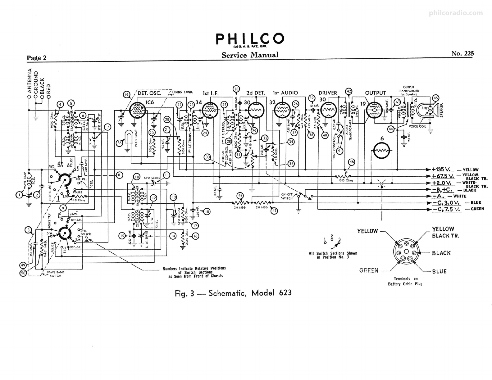
No. 225 Service Manual
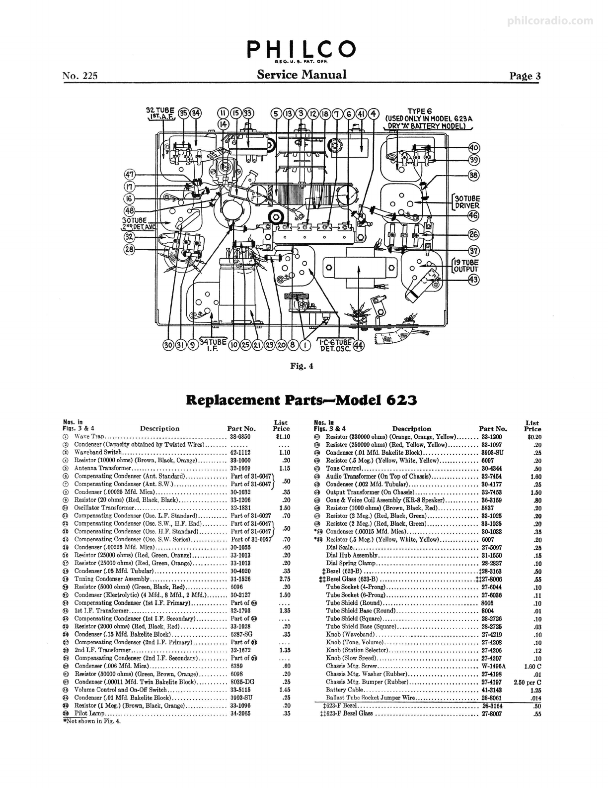
Fig. 4
Replacement Parts~Model 623
Nos. In
Figs. 3 & 4 Description Part No.
<D '\'\"a~eTrap.......................................... 38-6850
® Conderu,er(Capacity obtainedby TwistedWires).... . .. . . .....
© WavebandSwitch.................................... 42-1112
© Resist-0r(10000ohms)(Brown,Black,Orange)........... 33-1000
© AntennaTraru,former................................. 32-1669
List
Price
$1.10
1.10
.20
1.15
~
Compensat(ngCondenser(Ant. Standard)..........•.... P.artof31-6047} 5
(D CompensatmgCondenser(Ant. S.W.)................... Part of 31-6047 · O
© Condenser(.00025Mfd. Mica)......................... 30-1032 .35
© Resistor(20ohms)(Red,Black,Black)................ 33-1206
0 OscillatorTransformer................................ 32-1831
@ CompensatingCondenser(Oac.L.F. Standard)........... Part of31-6027
.20
1.50
.70
0 Compensat!ngCondenser(Osc.S.W.,H.F. End)......... Part of 31-6047}
0 CompensatmgCondenser(Osc.H.F. Standard).......... Part of31.-6047 .5o
0 CompensatingCondenser(Osc.S.W.Series)............. Part of31-6027 .70
@ Condenser(.00225Mfd. Mica)......................... 30-1055 .40
0 Resistor(25000ohms)(Red, Green,Orange)............. 33-1013 .20
@ Resist-Or(25000ohms) (Red, Green,Orange)............ 33-1013
@ Condenser(.05Mfd. Tubular)......................... 30-4020
0 TuningCondenserAssembly........................... 31-1526
0 Resist-Or(5000ohmJ)(Green,Black,Red) ............... 6096
O Condenser(Electrolytic)(4 Mfd.,8 Mfd.,2 Mfd.)........ 30-2127
~
CompensatingCondenser(1st I.F. Primary)............. Part of@
@ let l.F. Transformer.................................. 32-1793
0 CompensatingCondeneer(1st I.F. Secondary).... . .. . . .. Part of@
@ Resistor(2000oluna)(Red, Black,Red)................ 33-1028
0 Condenser(.15Mfd.BakeliteBlock)................... 6287-SG
@ CompensatingCondenser(2nd I.F. Primary)............ Part of@
0 2ndI.F. Transformer................................. 32-1672
0 CompenaatingCondenser(2nd I.F. Secondary).....•.... Part of 0
0 Condenser(.006Mfd. Mica)........................... 6359
@ Resi,,tor(50000ohms)(Green,Brown,Orange).......... 6098
0 Condenser(.00011Mfd. TwinBakeliteBlock)......•.... 8035-DG
0 VolumeControland On-OffSwitch..................... 33-5115
0 Condenser(.01Mfd. BakeliteBlock).. . . .. . . .. . . .. . . .. . 3903-SU
0 Resistor(1 Meg.)(Brown,Black, Orange)............... 33-1096
O Pilot Lamp.......................................... 34-2066
*Not shownin Fig. 4.
.20
.35
2.75
.20
1.50
1.35
.20
.35
1.35
.60
.20
.25
1.45
.25
.20
.35
Nos.In
Figs, 3 & 4 Description Part No.
@ Resistor(330000ohms)(Orange,Orange,Yellow)........ 33-1200
@ Resister (250000ohms)(Red, Yellow,Yellow)........... 33-1097
O Condenser(.01 Mfd. BakeliteBlock)................... 3903-SU
@ Resistor(.5 Meg.)(Yellow,White, Yellow).............. 6097
@ ToneControl.. ...................................... 30-4344
@ AudioTransformer(On Top of Chassis)................. 32-7454
@ Condeneer(.002Mfd. Tubular)........................ 30-4177
@ Output Transformer(OnCha.ssis)...................... 32-7453
@ Cone& VoiceCoilAssembly(KR-8 Speaker)............ 31\-3159
@ Resiator(1000ohw) (Brown,Black,Red) ..........••.. 5837
@ Resistor(2 Meg.)(Red, Black,Green).................. 33-1025
@ Resistor(2 Meg.)(Red,Black,Green).................. 33-1025
•@ Condenser(.00015Mfd. Mica)......................... 30-1033
•o Resistor(.5 Meg.)(Yellow,White,Yellow).............. 6097
DialScale...... .. .. .. .. .. . .. .. . . . .. . . .. .. . . .. . .. . .. . 27..5097
Dial Hub Assembly.................................. 31-1550
Dial SpringClamp... .. . . . . ... . . .. . . .. . . . .. . .. .•. . .. . 28-2837
:j:Bezel(623-B)....................................... t28-3163
ti BezelGlass(623-B)................................. U27-8006
Tube Socket(4-Prong)........ . . . ... . .. . .. . . . .. . .. . . .. 27-6044
TubeSocket(6-Prong)................................ 27-6036
Tube Shield(Round)................................. 8005
Tube ShieldBase(Round)............................ 8004
Tube Shield(Square)..... . . . ... . . .. . . .. . . .. . .. .•. . . .. 28-2726
Tube ShieldBase (Square).. ... .. .. . . .. . . . .. . . .. . .. . . . 28-2725
Knob (Waveband)................................... 27-4219
Knob(Tone.Volume)................................ 27-4208
Knob(StationSelector)............................... 27-4206
Knob(SlowSpeed)................................... 27-4207
ChassisMtg. Screw.......... ,........................ W-1496A
ChassisMtg. Washer(Rubber)...........••........... 27-4198
ChassisMtg. Bumper(Rubber)........................ 27-4197
Battery Cable....................................... 41-3143
Ballast Tube RocketJumper Wire...................... 28-8061
t623-F Bezel......................................... 28-3164
H623-F BezelGlass ................................... 27-8007
Page 3
List
Price
$0.20
.20
.25
.20
.50
1.60
.25
1.50
.80
.20
.20
.20
.35
.20
.25
.15
.10
.50
.55
.10
.11
.10
.01
.10
.03
.10
.10
.12
.10
1.60C
.01
2.50per C
1.25
.014
.50
.55
philcoradio.com

PH I LCO
RIG. u.s. PAT. or,.
Page 4 Service Manual No. 225
3. Adjust the signal generator to a frequency of 460 K.C.
Place the receiver in operation with the dial turned to the low
freque.ncy end of the standard broadcast band, wave band
switch to extreme left (clockwise), and have the volume control
adjusted near its maximum setting. Adjust the signal genera-
tor attenuator for approximately half-scale reading of the
output meter.
4. The I.F. compensating condensers are located at the tops
of the 1.F. coil shields and adjusted by turning the two screws
in top. Adjust condensers @ and @ (2d I.F. primary and
secondary) for maximum reading in the output meter, and
then condensers @ and @ (1st I.F. primary and secondary).
Adjustment of Wave-Trap
1. Connect the signal generator leads to the antenna and
ground terminals of the receiver. Replace the grid clip on the
1C6 grid cap.
2. With the wave-band switch of the receiver still in the
extreme left (broadcast position), turn the station selector
to 550 K.C.
3. With the signal generator in operation at 460 K.C.,
adjust the wave-trap CDcondenser until a MINIMUM
reading is obtained on the output meter. The wave-trap
compensator is reached from rear of chassis.
Adjustment of High and Low
Frequency Compensators
1. With the wave-band switch still at Position No. 1 (broad-
cast band), set the dial at 150 K.C. Set the signal generator
at 1.5 M. C. and adjust compensators @ and © for
maximum output. These are the oscillator and antenna
"H.F. standard" compensators respectively.
2. Tune the receiver and the signal generator to 600 K.C.
and adjust compensator @ (screw) for maximum output.
This is the oscillator standard series (L.F.) compensator.
3. Turn the wave-band switch to the extreme right (short-
wave band) and adjust the station selector to 18.0 megacycles.
Set the signal generator at 18 M.C. Adjust the oscillator S.W.,
and antenna S.W. compensators for maximum reading in the
output meter. These are numbered @ and (i) respectively
in figure No. 2.
4. Turn the tuning dial to 6.0 M.C., set the signal generator
at 6.0 M.C., and adjust condenser@ osc. series (S.W.) (nut)
to maximum signal.
The NEWESTand BESTevent in Radio Service *
RADIO MANUFACTURERS SERVICE
■ ■ ■
comes to the Public
... thru "WESTERNUNION"I
Benefits:
FortheDistributor:Gives frequent contactwith members of R.M.S.
FortheDealer-R.M.S.Member:Brings in more business.
FortheRadioOwner:Assures easily-obtained, dependable service.
CO-OPERATE-DOYOURPARTI
PH I LC0
SU G, U.S. PAT. OFF.
Parts and Service Division
August1935 Printed in U.S. A.
philcoradio.com
Other Philco Radio manuals

Philco
Philco 37-640 User manual

Philco
Philco 116 User manual

Philco
Philco 121 User manual

Philco
Philco PHOTOFACT 49-1150 User manual

Philco
Philco 121 User manual

Philco
Philco 37-670 User manual

Philco
Philco 16 Reference manual

Philco
Philco 37-630 User manual

Philco
Philco 37-660 User manual

Philco
Philco 77 User manual