manuals.online logo
Brands
  1. Home
  2. •
  3. Brands
  4. •
  5. Philco
  6. •
  7. Radio
  8. •
  9. Philco 611 User manual

Philco 611 User manual

SERVICEBULLETIN
No.!!4
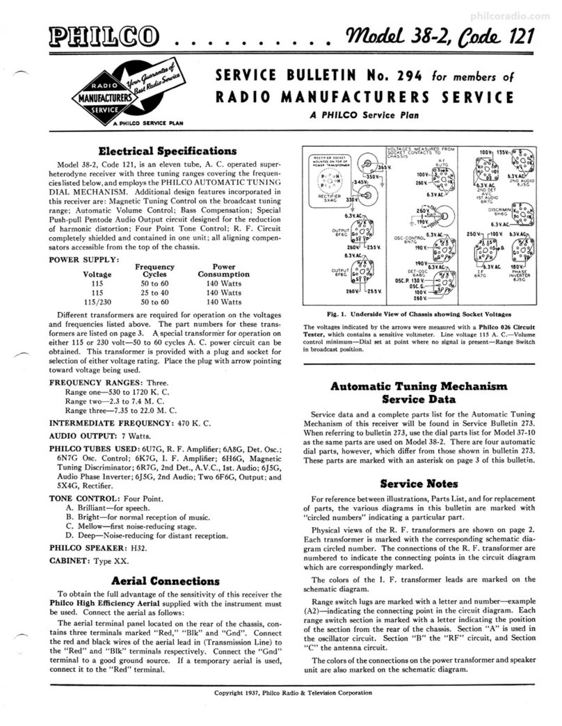
Specifications
Type Circuit: Superheterodyne, with pentode
output; built in connections for Philco All-wave
aerial; aerial selector built into and operated by
wave-band switch.
Power Supply: 115 volts, Alternating or Direct
Current.
Tubes Used: 1 type 6A7, Detector-Oscillator; 1
type 78, I.F.; 1 type 75, 2d Detector and 1st A.F.;
1 type 43 Output; 1 type 2525 Rectifier.
Wave Bands: Three-(1) Standard (with some
Police); (2) Police; (3) Short-wave.
Coverage of Each Band: Band 1, 530-1720 K.C.;
Band 2, 2300 to 2500 K.C. (2.3-2.5 M.C.); Band 3,
5700-18000 K.C. (5.7 to 18.0 megacycles).
Tuning Drive: Dual gear drive, ball bearing. 50
to 1 ratio for slow-speed tuning. 6 to 1 on main
drive.
Tone Control: 2-position.
Intermediate Frequency: 460 K.C.
Power Consumption: 50 watts.
Speaker: 611-B (Baby Grand): P-28; 611-F
(Console): S-15.
0
02 o
• • • 'fflJJ.rM611
For Members of
RADIO MANUFACTURERS SERVICE
A PHILCO SERVICEPLAN
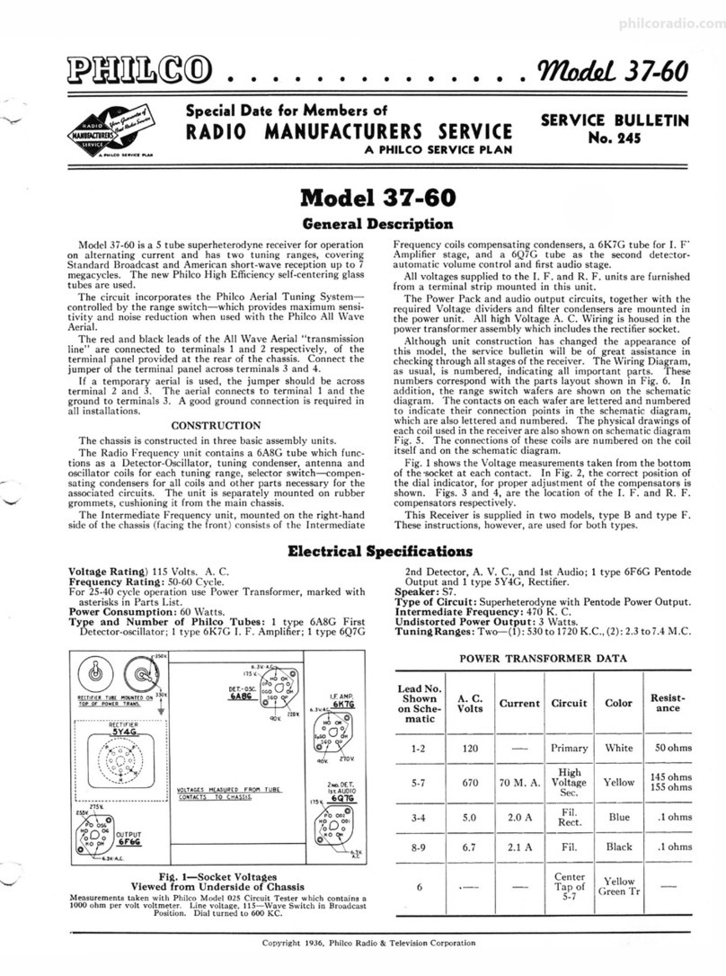
Tube Socket Voltages
(Measured at 115volts A.C.)
43
OUTPUT
75 6-A-7
01 ZND,DET.
\ST.,A.F. DET.-OSC. 25Z5
41V. RECTIFIER.
0.8V,
Fig. 1. Tube Sockets as viewed from bottom.
Above voltages were obtained by using a PHILCO type 025 Circuit Tester (or 048A All-
purpose Tester), using test prods applied to underside of chassis. Volume control at minimum;
dial at 55; waveband switch counter-clockwise (band 1). S-15 Speaker used.
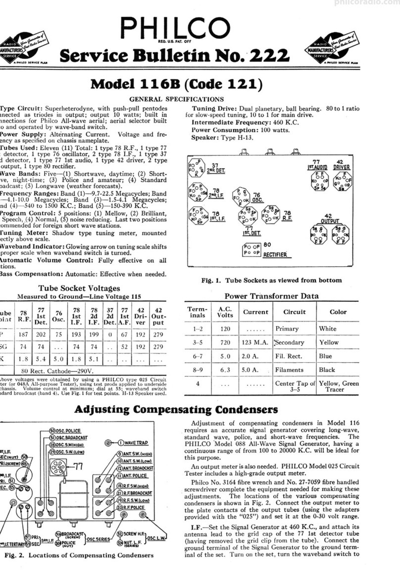
ADJUSTINGCOMPENSATINGCONDENSERS
c.,L.F.,51'0.(ScREW)~====!=cc!:
(NUT)
6-A-7
0 0------G)ANT. sr·o
~
~'-=--@ANT. S.W.
14OSC.S.W.(M.F.ENO)
'-----Cl3 OSC.H.F.STh.
Fig. 2. Locations of Compensating Condensers
The adjustment of the compensating condensers in Model 611
requires a signal generator covering the broadcast and police
band, and also one capable of producing a signal at certain fre-
quencies in the short wave band. The Philco Model 088 All-Wave
Signal Generator covers these requirements perfectly. An output
meter is also required. Philco Model 025 or 012 unit is recom-
mended. The location of all compensating condensers is shown
in Fig. 2. Adjustment of I. F.
1. Remove the antenna connection from the receiver. Remove
the grid clip from the first detector (type 6A7 tube), and attach
the "ANT" output lead from the signal generator to the grid
cap of this tube.
2. Connect the output meter to the plate and cathode of the
output tube by means of the adapters provided with the "025"
or to the two bottom prongs of the speaker plug. Set it at the
0-30 volt range.
philcoradio.com
Page 2
<(
z
z::..:::
PH I LCO
a1G.u.a. •AT. OH.
SERVICEMANUAL
LLIU
~<( C
<(
~
~
DET.OSC. Gp
~
l 1st·I.F. 2d DET.-lstA.F.
Gr-ti I
I
I
,'TUNIN~-CONO.-7
I
I
I I T I/«\c4s
MF. _>.:/
~
-•11~•--
-,-,-1-0
~
~
@ ®-VOLUME/
CO~TROL
~
0.5 MEG.7
1 5 3
0/ @Jr.<
~
~
4
..
~--+lh'
G)I/~ .-1-® ,,..
6
1 i! O ---·- -
~
... -~-J:,1.l I I I-@
/
~
ST!). @ _l ...,sj-+-- -
/":;\ 1 t POLICE ~l\1
~
~I .,; 'h.----
~
"'-:] . "'
C I /
~
llj 2 mo MMF.
~:iz·l?~===-----
~1 L
I ,
I 1......,_
·L.-..1 "-
Numbers IndicateRelative Positions
of Switch Sections
as Seen from Frontof Chassis
All Switch Sections Shown
In Position No. 3
Fig. 3 - Schematic Diagram of Model 61 I
Note 1: Cathode condenser of 78 tube (lower portion of (@) is .1 mfd.
instead of .01 mfd. shown above.
Note 2: Condenser ® is .00025 mfd. instead of .0008 mfd. as shown above.
Model 611
~(si\
OUTPU ..
~
w.,,-
~~
~
5gj. SPEAKE!\
~2lr~~~~
11[g;
11~~
~l'®
philcoradio.com
Model 611 PHILCO SERVICEMANUAL
Fig. 4
·Z.5TUBE
·crlFIER
REPLACEMENTPARTS-MODEL611
Nos.In
Figs. 3 & 4 Description Part No.
© WaveTrap.............................................. 38-6850
© Conderu,er(.0014Mfd. Mica)...•.•.....•.........•.....•.. 7007
© WavebandSwitch...................•...........•.•.•.... 42-1112
© Condelli!er-CapacityObtainedby TwistedWires).... .. .. .. . . .....
® Resistor(5000ohms)(Green,Black,Red).....•..........•.• 33-1001
© AntennaTransformer.....•......................•.•.•.... 32-1781
List
Price
Sl.10
.30
1.10
.20
1.15
0 CompensatingCondenser(Antenna,Standard)............... Part of31-6047} 50
© CompensatingCondenser(Antenna S.W.)................... Part of 31-6047 ·
® Condenser(.00025Mfd. Mica).....•....................... 5858 .25
O Resi,tor (20 ohms)(Red,Black,Black)..............•...... 33-1206 .20
@ Oscillat-0rTransformer.............................•.•.... 32-1831 1.50
@ CompensatingCondenser(Osc.L.F. Standard)..........•.... Part of 31-5027 .70
@ Compansat!ngCondenser(Osc.H.F. Standard).............. Part of 31-6047}
<3 CompensatrngCondenser(Osc.S.W.H.F. End).........•.... Part of31-5047
0 CompensatingCondenser(Osc.S.W.L.F. End)...... . . . .. . •. Part of 31-6027
0 Condell3er(.00225Mfd. Mica)...•......................... 30-1055
@ TuningCondenserAssembly............................... 31-1528
0 Resistor(120000ohms)(Brown,Red, Yellow)........•...... 83-1128
0 Resistor(120000ohms)(Brown,Red, Yellow)............... 33-1128
0 Resistor(200ohmsFlexible)(Red,Black,Black). . . .. . .. . . . . 7217
@ Condenser(.1 Mfd.TwinBakeliteBlock)..........•........ 4989-DG
O Condenser(.05Mfd. Tubular)............................. 30-4020
0 CompensatingCondenser(1st I.F. Primary).•....•.......... Part of O
0 1st l.F. Transformer.............................•..•..... 32-1671
0 CompensatingCondenser(1st I.F. Secondary)............... Part of O
0 Resistor(300ohmsFlexible)(Orange,Black,Black).......... 33~010
@ Con<len,er(.1 Mfd.& .01Mfd.BakeliteBlock).•............ 4989-FU
0 Pilot Lamp.............................................. 34-2068
0 CompensatingCondenser(2d I.F. Primary)................. Part of 0
@ 2d I.F. Transformer..•..........................•••...... 32-1672
@ CompensatingCondenser(2d I.F. Sooondary).......•.....•.• Part of O
0 Resistor(1000ohms)(Brown,Black,Red).............•.••• 5837
@ Resistor(2 Megs.)(Red,Black,Green)...•..........•...•.. 33-1025
0 Resistor(50000ohms)(Green,Brown,Orange)...... •. ••. . . • 6098
@ Condenser(.00011Mfd. TwinBakeliteBlock).........•••..• 8035-DU
@ Condenser(.00011Mfd. Mica)............................. 30-1031
0 Condenser(.15Mfd. TwinBakeliteBlock).................. 6287-DU
0 Condenser(.01Mfd. BakeliteBlock)....................... 3903-SU
0 VolumeControl& On-OffSwitch....................•...... 33-5114
.50
.70
.40
3.75
.20
.20
.20
.40
.20
1.35
.20
.40
.16
1.35
.20
.20
.20
.25
.20
.40
.25
1.45
Nos.In
Figs. 3 & 4 Description Part No.
@ Resistor(50000ohms)(Green,Brown,Orange)........•..... 4237
@ 'Resistor (13000ohms)(Brown,'Orange,Orange)............. 3766
@ Resistor(15000ohms)(Brown,Green,Orange).............. 5278
@ Resistor(70000ohms)(Violet,Black,Orange)............... 33-1115
@ Resistor(240000ohms)(Red, Yellow,Yellow)........•...... 33-1097
@ Condenser(.015Mfd.BakeliteBlock)...................... 3793-SU
@ Resistor(.5 Meg.)(Yellow,White, Yellow).................. 6097
@ ToneControl..... . .. .. .. .. .. .. .. . . .. . . . .. .. . . .. . .. . . . .. . 3()..4345
@ Resistor(400 ohmsFlexible)(Yellow,Black,Black).......... 33-3016
@ Condenser(Electrolytie-10 Mfd., 10Mfd.)................. 30-2125
I@ Condenser(.02Mfd.Tubular)............................. 30-4215
@ Output Transformer.............................•........ 32-7395
O Cone& VoiceCoilAssembly(S-15Speaker)................. 3~157
0 Field Coil& Pot Assembly(S-15Speaker)................... 36-3519
O Resistor(20ohmsFlexible)(Red,Black,Black)......•...... 33-1206
@ Condenser(.25Mfd.Tubular)............................. 30-4146
O Resistor(I Meg.)(Brown,Black,Green)............•....... 33-1096
@ Resistor(.5 Meg.)(Yellow,White,Yellow)... , .............. 6097
@ Condenser(Electrolytic,16Mfd.).......................... 30-2124
@ Filter Choke............................................. 32-7018
@ Filter Choke............................................. 32-7452
@ Resistor(15 ohm.s,130ohms-Wirewound).................. 33-3213
@ Condenser(.05Mfd. BakeliteBlock)....................... 3615-SU
Dial Scale............................................... 27-5097
Dial Hub and Set ScrewAssembly......................... 31-1550
Dial SpringClamp....................................... 28-2837
Knob (Tone,Volume).................................... 27-4208
Knob (Waveband)....................................... 27-4219
Knob (Station Selector)................................... 27-4206
Knob (Fine Tuning)...................................... 27-4207
Socket(6 Prong)......................•.......••......... 27-6036
Socket(7 Prong)......................................... 27-6037
Bezel.... ... .. . . .. . . . . .. . . . . . ... .. ... . .. . . .. . . . . . .. .. .. . 28-2928
Bezel
Glass....................•..............•.......... 27-2887
ChassisMtg. Screw...........•........................... W-1496A
ChassisMtg. Washer..................................... 27-4198
Tube ShieldBody...... .. . . .. . . . . .. . . .. .. . . .. . •.. . . .. . .•. 28-2726
Tube ShieldBase.........•....... , .......•.......•...... 28-2725
Page 3
List
Price
S0.20
.20
.20
.20
.20
.35
.20
.50
.20
1.20
.20
1.10
.80
2.80
.20
.25
.20
.20
.75
.75
1.50
.90
.50
.35
.25
.15
.10
.10
.10
.12
.10
.11
.11
.35
.60
1.60per C
.01
.10
.o~
philcoradio.com
Pase 4 PHILCO SERVICEMANUAL Model 611
3. Adjust the signal generator to a frequency of 460 K.C.
Place the receiver in operation with the dial turned to the low
frequency end of the standard broadcast band, wave band switch
to extreme left (clockwise), and have the volume control adjusted
near its maximum setting. Adjust the signal generator attenuator
for approximately half-scale reading of the output meter.
4. The I.F. compensating condensers are located at the tops
of the I.F. coil shields and adjusted by turning the two screws
in top. Adjust condensers @ and ® (2d I.F. primary and
secondary) for maximum reading in the output meter, and then
condensers @ and @ (1st I.F. primary and secondary).
Adjustment of Wave-Trap
1. Connect the signal generator leads to the antenna and
ground terminals of the receiver. Replace the grid clip on the
6A7 grid cap.
2. With the wave-band switch of the receiver still in the
extreme left (broadcast position), turn the station selector to
550 K.C.
3. With the signal generator in operation at 460 K.C., adjust
the wave-trap (D condenser until a MINIMUM reading is
obtained on the output meter. The wave-trap compensator is
reached from rear of chassis.
Adjustment of High and Low
Frequency Compensators
1. With the wave-band switch still at Position No. 1 (broad-
cast band), set the dial at 1500 K.C. Set the signal generator
at 1.5 M. C. and adjust compensators @and 0 for maximum
output. These are the oscillator and antenna "H.F. standard"
compensators respectively.
2. Tune the receiver and the signal generator to 600 K.C. and
adjust compensator@ (screw) for maximum output. This is the
oscillator L.F. standard compensator.
3. Turn the wave-band switch to the extreme right (short-
wave band) and adjust the station selector to 18.0 megacycles.
Set the signal generator at 18.0 megacycles. Now adjust the
oscillator S.W., and antenna S.W. compensators for maximum
reading in the output meter. These are numbered @ and ®
respectively in figure No. 2.
4. Turn the tuning dial to 6.0 M.C., set the signal generator
at 6.0 M.C., and adjust condenser@ osc. L.F., (S.W.) (nut) to
maximum signal.
New PHILCOCABINETPOLISH
■
•
■
MAKES POLISHINGEASY
0 Here is something you have_long
wanted: a dependable, economical, Fur•
niture Polish that would give a beautiful
high-gloss, non-sticky finish, with a mini-
mum of rubbing when applying,
0 Developed asa result of extensive
research by Philco's chemical engineering
department, this new special Furniture
Polish "does the trick" most satisf;ictorily
and with the smallest amount of polish
and a minimum of time and effort-and
with not the slightest harm to the most
delicate finish.
0 Order a case at once. Save time
and expense on your polishing-and
keep your display cabinets in the pink of
appearance-it will pay For itself a
hundred times over.
Printed in U. S. A.
• Quickly applied with mini-
mum effort
• Gives Beautiful Gloss Finish
• Doesn't leave surface oily
• Extremely economical
• Cannot damase finest furni-
ture
~.uiol
FURNITURE
POLISH
•
Idealfor
RAX>10CABIKF.TS
PlA><OS
AUTOKOBli.£S
l'lNE FUR\llTDI\E
P~IU:.O EU.010'& TELE\115t0tt
CORPORATION
~-- ---!fl/I.
•..;;.~.,1,111~
*
Sold only in attractive cartons List
of six 8-oz. bottles-Part No. 45-1176 ................ $3.30
PH I LCO
A.I G. U.S. PAT. OS:F.
Parts and Service Division August 193~
philcoradio.com

Other Philco Radio manuals

Philco D-592 User manual

Philco

Philco D-592 User manual

Philco 28 User manual

Philco

Philco 28 User manual

Philco 116 User manual

Philco

Philco 116 User manual

Philco 200 User manual

Philco

Philco 200 User manual

Philco 37-675 User manual

Philco

Philco 37-675 User manual

Philco PRR1005BT User manual

Philco

Philco PRR1005BT User manual

Philco 39-55 User manual

Philco

Philco 39-55 User manual

Philco 37-640 User manual

Philco

Philco 37-640 User manual

Philco 80 User manual

Philco

Philco 80 User manual

Philco 37-620 User manual

Philco

Philco 37-620 User manual

Philco 37-116 User manual

Philco

Philco 37-116 User manual

Philco 16 Reference manual

Philco

Philco 16 Reference manual

Philco 121 User manual

Philco

Philco 121 User manual

Philco 96 User manual

Philco

Philco 96 User manual

Philco 37-670 User manual

Philco

Philco 37-670 User manual

Philco 37-630 User manual

Philco

Philco 37-630 User manual

Philco 121 User manual

Philco

Philco 121 User manual

Philco 623 User manual

Philco

Philco 623 User manual

Philco 121 User manual

Philco

Philco 121 User manual

Philco 37-60 User manual

Philco

Philco 37-60 User manual

Philco 144 User manual

Philco

Philco 144 User manual

Philco 121 User manual

Philco

Philco 121 User manual

Philco CSP790BC User manual

Philco

Philco CSP790BC User manual

Philco 66 User manual

Philco

Philco 66 User manual

Popular Radio manuals by other brands

Silvercrest SKR 800 C3 Operating instructions and safety instructions

Silvercrest

Silvercrest SKR 800 C3 Operating instructions and safety instructions

MasterForce 241-0346 Assembly & operators manual

MasterForce

MasterForce 241-0346 Assembly & operators manual

Tait TM9400 Specification manual

Tait

Tait TM9400 Specification manual

Teac CRX45iP user manual

Teac

Teac CRX45iP user manual

Teac SR-L200I-W owner's manual

Teac

Teac SR-L200I-W owner's manual

SOUNDMASTER SCD5100RO manual

SOUNDMASTER

SOUNDMASTER SCD5100RO manual

Emerson NR52 owner's manual

Emerson

Emerson NR52 owner's manual

Nokia 9500 MPR user manual

Nokia

Nokia 9500 MPR user manual

Metra Electronics Satellite Radio Use and care

Metra Electronics

Metra Electronics Satellite Radio Use and care

Motorola MaxTrac 100 operating instructions

Motorola

Motorola MaxTrac 100 operating instructions

Bush WI-1810 instruction manual

Bush

Bush WI-1810 instruction manual

Bonso BS001 owner's manual

Bonso

Bonso BS001 owner's manual

Jensen JCR-310 user manual

Jensen

Jensen JCR-310 user manual

Retevis RB28 user manual

Retevis

Retevis RB28 user manual

Avox INDIO user guide

Avox

Avox INDIO user guide

Mesqool CR1009Pro quick start guide

Mesqool

Mesqool CR1009Pro quick start guide

Roberts Play user guide

Roberts

Roberts Play user guide

Bosch PRA 10 Original instructions

Bosch

Bosch PRA 10 Original instructions

manuals.online logo
manuals.online logoBrands
  • About & Mission
  • Contact us
  • Privacy Policy
  • Terms and Conditions

Copyright 2025 Manuals.Online. All Rights Reserved.