Philco 37-660 User manual

-• • • • • • • • • • • • • • ffflodRL37-660
FOR MEMBERS OF
RADIOMANUFACTURERSSERVICE SERVICE BULLETIN
No. 257
SERVICE DATA
Model 37-660 is a 9 tube superheterodyne receiver ·designed for
operation on alternating current. It has four tuning ranges, covering
standard broadcast and short-wave frequencies. The chassis is
constructed in four basic assembly units, concentrating the R.F.,
I.F., Audio and Power circuits in individual units .
The circuit includes the PHILCO Foreign Tuning System -
controlled by the range switch-providing maximum sensitivity and
noise-reduction, when used with the Philco High-Efficiency Aerial;
automatic bass compensation in the volume control circuit; shadow
tuning; automatic volume control, and a push-pull pentacle output
circ4it. AERIAL CONNECTIONS
The red and black leads of the High-Efficiency Aerial "trans-
mission line" are connected to terminals l and 2 respectively, of the
terminal pa11el provided on the rear of the chassis. Connect the
jumper on the terminal panel across terminals 3 and 4.
If a temporary aerial is used, the jumper should be across terminals
2 and 3. The aerial connects to terminal 1 and the ground lead to
terminal 3. A good ground connection is desirable in all installations.
REPLACING DIAL
To replace the dial, remove the clamp holding the dial to the hub,
by turning clamp counter-clockwise, using the two holes provided on
the clamp for this purpose.
REMOVING MASK ARM & LINK ASSEMBLY
First remove dial, then loosen set screw of dial hub and remove
the hub and felt' washer from the shaft . Now loosen screws holding
indicator bracket and lens assembly, and move bracket forward
about ½ inch. The assembly may now be removed by loosening set
screw of range switch arm, then pull arm off of range switch shaft.
REMOVING SWITCH & COIL ASSEMBLIES OF R.F. UNIT
To replace any part in the switch and coil assemblies of the R.F.
Unit, each assembly can be removed separately as follows:
First remove the tuning dial, mask and arm assembly . Remove
the center mounting screw on the rear of the R.F. Unit. Then lift
the rear of the unit and push forward until the rubber mounting
grommets, on each side of the unit, clear the mounting slots. The
unit is then lifted far enough from the chassis for removal of the two
screws holding the selector switch indexing plate and shaft (front of
unit). Then pull shaft straight out from the unit. Also, remove the
volume control shaft by releasing the retaining clip, inside the
chassis, from the shaft .
IMPORTANT-When selector switch shaft is replaced, care
should be taken to have all wafer rotors in the same position,' so that
the key on the switch shaft will slide freely into the notched hole in
each wafer rotor. NEVER force shaft into rotors.
Servicing Stages-It is necessary to unsolder some connecting
leatls in order to release the stage for servicing. If all the following
connections are unfastened the stage will be entirely released .
Ordinarily only one or two leads need be loosened in order to change
coils, replace coupling condensers, or replace switch sections.
ANTENNA ASSEMBLY-Rear Section
1. Unsolder the wires which connect the antenna panel and I.F.
Unit to the range switch and assembly shield plate ground leads.
2. Unsolder the two leads from the gang condenser terminal panel
which connect to the range switch. Also lead of tubular condenser
(7) at the ground lug on the R.F. Unit.
3. Remove screw holdin g shield plate to the unit base. This
screw is located in the tight hand corner of the shield plate, facing
the rear underside of the chassis. The assembly can then be removed.
R.F. ASSEMBLY-Middle Section
1. Unsolder the wires from the I.F. Unit and the 6K7G plate
contact in R.F. Unit which connects to the range switch : Then
remove ground leads of shield plate.
2. Unsolder the leads from the gang condenser terminal panels
and the lead of tubular condenser (18) at the ground lug on R.F.
Unit base.
3. Remove the screw holding shield plate to the unit base. This
screw is located in the right hand corner of the shield plate facing the
rear underside of the chassis. Then pull assembly straight out.
OSCILLATOR ASSEMBLY-Front Section
1. The oscillator assembly can be removed by unscrewing the two
screws located on each side of the R.F. Unit.
2. Unsolder the wires connecting range switch to bakelite con-
denser (78) in the power unit, electrolytic condenser (21) in the R.F.
Unit and OSC plate contact on the 6A8G socket .
3. Remove the leads from the gang condenser terminal panels and
the lead of Mica condenser (24) at the ground lug on R.F . Unit base.
Electrical Specifications
Power Supply: 115 V.
Frequency: 50-60 cycle.
For 25 to 40 cycle operation, use the Power transformer marked with asteris k in
the parts list.
Consumption: 130 Watts.
Intermediate Frequency: 470 K. C.
Output: 10 Watts.
Philco Tubes: 6K7G-R.F. Amplifier; 6A8G-Oscillator and first detector;
6K7G-I.F. Amplifier; 6J5G-2nd detector, A.V.C.; 6K5G-lsCAudio; 6J5G
Phase Inverter; 2-6F6G-Output; 5Y4G-Rectifier.
Tuning Ranges : Range 1-530 to 1720 K. C.; Range 2-2 .3 to 7.4 M. C.; Range
3-7.35 to 11.6 M. C.; Range 4-11.5 to 18.2 M. C.
Speakers; X cabinet_:_H-27; B cabinet-K-36 .
ri
...
.:..
...
i
~ ~
~
3
"'
ci
: 5P[AK[R C-111.1.=-=-
~
Fl(LO COIL
3
~
a:
'-'
Speaker Wiring for Types K-36 and H-27
,--- 3so:.oc----,
1 RECTIFIER I
1 5Y4G 1
I . I
I
,
✓--...._
I
I / ::o \ I
I G,--..o i I
: I a,;--//,' I
I ,_
✓'
I
I '----+--_, I
I I
L____________ J
RECTIFIERSOCKETMOUNTED
ONTOPOFPOWERTR~NS.
FRONTOF CHASSIS
385V. OSC.PL~TE14
DSC.GRID
PHASEINVERTER
SJSG
Fig. 1-SOcket Voltages-Underside of Chassis View
The voltages indicated by arrows were measured with a Philco 025 Circuit
Tester which contains a voltmeter having a resistance of 1000 ohms per volt.
Volume Control at minimum, range switch in broadcast position, line voltage
115 A. C.
Copyright 1936, Philco Radio & Television Corporation
philcoradio.com

No. 257 PHILCO Service Bulletin
/,/
sft • • • • • ·1110 @
>~> >--a=r'--,J:',
1:t ·TAP[' ~-
~4~B-4=ffl--3 4 3 ~3
~~
:r-05,.F.
~
7''@
~@
;a';"!iJ-,,lt'
~
. :=m'•fm·1
~
4 -T~
~
-~P
~
3
@ANT.·RANGE3 @ANT. · RANCE4 @R.F. ·RANGE3 @R.f. RANGE4 ® osecRANGE3 ®osc.-RANGE4 '-------------------=:::·:c. ·_______________________ _J
., =NOTE=
..t :
~
r All S'fflTCHE~ SHOWN \N POSITION
w t>
~
~
Ho .\ (BROADCAST).
~
?i
~
Z SOLID ARE"- INDICATES REAR OF
~
'f ,
~
SWITCH WAFE:R •
..
~
·~
~
f
l~~~~~
~~}~R~NDICATtS FRONT Of
0
~
. ····-· ···-· · ••• • .... .... -- .... .
0304~F3f4
~
• 0 D5 E2 0 ° ES Fl •' F5
D1 ,
~
Db El , r 1/', Eb Fl ,. • fb
o o r o a o
01, · 1 _ , 01 m 0 - El rn · ° F7
011 ' - 08 Ell " ' EB F8
D DID pq
~
ElO EQ FIO F'l GIO G'l
DIBICIION
Fig. 2-Schematic Diagram
Model 37-660
( (
Page2
,ri
@l
<
~
,-
,-~
t
philcoradio.com

No. Z57 PHILCO Service Bulletin Page 3
POWERUNIT R.F..i AUDIOUNIT 1.F.UNIT
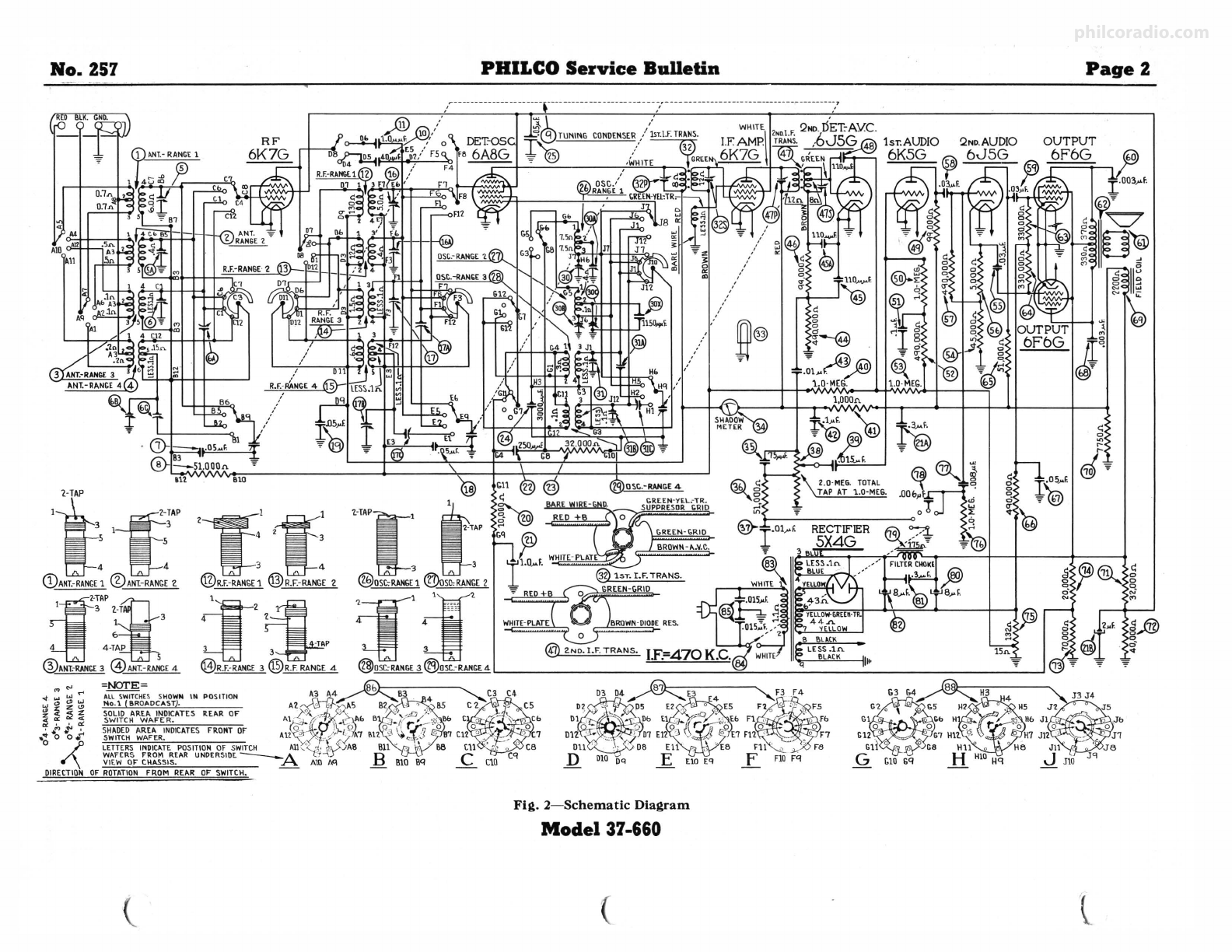
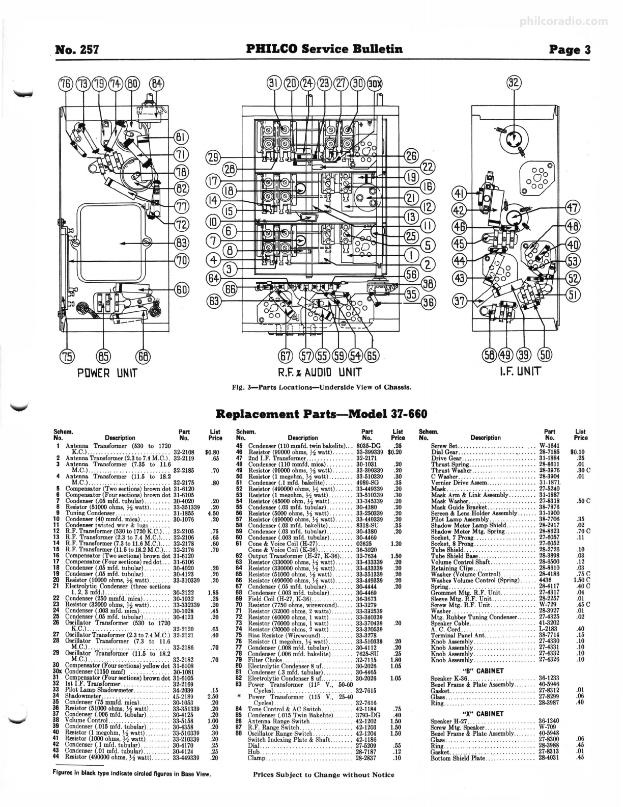
Fl~. 3-Parts Location-Underside View of Chassis.
Replacement Parts-Model 37-660
Sehem. Part
No. Description No.
1 Antenna Transformer (530 to 1720
K.C.
l. ..... . . .. .. . . .. . .. .. .. .. . . . 32-2108
2 AntennaTransformer (2.3to 7.4M.C.). 32-2119
3 Antenna Transformer (7.35 to 11.6
M.C.)............................ 32-2185
4 Antenna Transformer (11.5 to 18.2
M.C.)........... . ............... . 32-2175
5 Compensator (Two sections) browndot 31-6120
6 Compensstor (Four sections)browndot 31-6105
7 Condenser(.05 mfd. tubular) ......... 3.~020
8 Resistor (51000ohms,½ watt). 33-351339
9 Tuning Condenser....... . . .. . . 31-1855
10 Condenser (40 mmfd. mica). ...... 30-1076
11 Condenser twisted wire & lugs ...... .
12 R.F. Transformer (530to 1720K.C.)... 32-2105
13 R.F. Transformer (2.3 to 7.4 M.C.l.... 32-2106
14 R.F. Transformer (7.3to 11.6M.C.l.... 32-2178
15 R.F. Transformer (11.5to 18.2 M.C.)... 32-2176
16 Compensstor (Two sections) browndot 31-6120
17 Compensator(Four sections)red dot... 31-6106
18 Condeneer(.05 mfd. tubular) ...... ... 3~020
19 Condenser(.05 mfd. tubular) ... ... ... 3~123
20 Resistor (10000ohms, ½ watt) . ... ... 33-310339
21 Electrolytic Condenser (three sections
I, 2, 3 mfd.)........ .. ...... . ..... 30-2122
22 Condenser(250 mmfd. mica)......... 30-1032
23 Resistor (32000ohms, ½ watt). . . . . . . 33-332339
24 Condenser(.003 mfd. mica)......... .. 30-1028
25 Condenser(.05 mfd. tubular) ...... ... 3~123
26 Oscillator Transformer (530 to 1720
K.C.)..... ... ...... ....... ...... . 32-2120
27 OscillatorTransformer (2.3t-07.4M.C.) 32-2121
28 Oscillator Traneformer (7.3 to 11.6
M.C.)..... ... . ....... . ........... 32-2186
29 Oscillator Transformer (11.5 to 18.2
M.C.)...... .. ...... . .. .... .... . .. 32-2182
30 Compensator (Four sections)yellowdot 31-6108
30x Condenser(1150 mmf) ..... . .·. . . . . . 30-1081
31 Compcnsstor (Four sections) browndot 31-6105
32 1st I.F. Transformer....... . . ........ 32-2169
33 Pilot Lamp Shadowmeter. . . 34-2039
34 Shadowmeter.. .. ...... .... 45-2189
35 Condenser (75 mmfd. mica) . . . . . 30-1053
36 Resist-Or(51000 ohms,½ watt).. . . 33-351339
37 Condenser(.006 mfd. tubular) 3~125
38 VolumeControl...... . ... .... .. 33-5158
39 Condenser(.015 mfd. tubular) ... 3~358
40 Resistor (I megohm, ½ watt) .. . 33-510339
41 Resistor (1000ohms, ½ watt) ... 33-210339
42 Condenser(.I mfd. tubular) ... .. 3~170
43 Condenser(.OJmfd. tubular).... 3~124
44 Resistor (490000ohms, ½ watt). 33-449339
Lisi
Price
$0.80
.65
.70
.80
.20
.20
4.50
.20
.75
.65
.60
.70
.20
.20
.20
1.85
.25
.20
.45
.20
.65
.40
.70
.70
.15
2.50
.20
.20
.20
1.00
.20
.30
.20
,25
.25
.20
FiguresIn blacktype indicatecircledfigures in Base View.
Schorn.
No. Part
Description No.
45
48
47
48
49
50
51
52
53
54
55
56
57
58
59
60
61
Ccnderu,er(110mmfd. twin bakelite).. . 8035-DG
Resistor (99000ohms, ½ watt) . . .. .. . 33-399339
2nd I.F . Transformer.... . .. .. . ..... . 32-2171
C-Ondenser(110 mmfd. mica). . ... . .. . 30-1031
Resistor (99000ohms, ½ watt) . . . . . . . 33-399339
Resistor (I megohm, ½ watt) ........ . 33-510339
Condenser(.I mfd. bakelite).... ..... . 4989-00
Resistor (490000ohms,½ watt) ...... 33-449339
Resistor (I megohm,½watt) ......... 33-510339
Resistor (45000 ohm, ½watt) ........ 33-345339
Condenser (.03 mfd. tubular) ....... .. 3~380
Resistor (5000ohms, ½ watt). .. .. 33-250339
Resistor (490000
ohms,½ watt) .... .. 33-449339
Condenser (.03 mfd. bakelite). .. .. ... . 8318-SU
Condenser (.03 mfd. tubular) .. ....... 30-4380
Condenser (.003 mfd. tubular) ........ 30-4469
Cone& VoiceCoil (H-27).. ....... ... 02625
Cone & VoiceCoil (K-36).......... . . 36-3020
62 Output Transformer (H-27, K-36).. . . . 32-7634
63 Resistor (330000ohms, ½ watt). . . 33-433339
64 Resistor (330000ohms, ½ watt). . . . . 33-433339
65 Resistor (51000ohms, ½ watt ). .... . . 33-351339
66 Resistor (490000ohms, ½ watt) ... ... 33-449339
67 Condenser(.05 mfd. tubular) ..... .... 3~444
68 Condenser(.003 mfd. tubular) ....... . 3~469
69 Field C-Oil(H-27, K-36).. .. . . . .. .. 36-3673
70 Resistor (7750ohms, wirewound).. 33-3279
71 Resistor (32000ohms, 2 watts) .. . 33-332539
72 Resistor (40000ohms,·! watt) ..... 33-340339
73 Resistor (70000ohms, I watt). .. .. 33-370439
74 Resistor (20000ohms, 2 watt). 33-320539
75 Bias Resistor (Wirewound).... .. .. 33-3278
76 Resistor (I megohm, ½ watt) ... 33-510339
n C-Ondenser(.008mfd. tubular) ...... . . 3~112
78 Condenser(.006 mfd. bakelite).. 7625-SU
79 Filter Choke.......... ............. . 32-7115
SO Electrolytic Condenser 8 uf.. .. . . . . . . . 30-2026
81 Condenser (.3 mfd. tubular)... .. .. 3~465
82 Electrolytic Condenser8 uf.. .. .. .. .. . 30-2026
83 Power Transformer (II~ V., 50-60
Cycles)... .... ... . ....... ... . 32-7615
* Power Transformer (115 V., 25-40
Cycles).......... .. .. .. .. 32-7616
84 Tone Control & ACSwitch...... 42-1184
85 Condenser (.015Twin Bakelite). 3793-DG
e& Antenna Range Switch.. 42-1202
87 R.F. Range Switch.... . . 42-1203
88 Oscillator Range Switch 42-1204
Switch Indexing Plate & Shaft .. 42-1186
Dial. ... .. .. .. 27-5209
Hub 28-7187
Clamp.... .. . . .. . . .. .. . . 28-2837
List
Price
.25
S0.20
.20
.20
.30
.35
.20
.30
.20
.20
.20
.20
.35
.20
1.20
1.50
.20
.20
.20
.20
.20
.20
.20
.20
.25
1.80
1.05
1.05
.75
.40
1.50
1.50
1.50
.55
.12
.JO
Prices Subject to Chanite without Notice
Patt
Sehem.
No, Description No.
ScrewSet............... .... ... W-1641
Dial Gear... .. .. . . .. .. .. .. .. •. .. . . . 28-7185
Drive Gear..... .. .. .. .. .. .. 31-1884
~t~t~~1it::::::::::::::::::::::~tlm
C Washer.. . . . .. .. . . . . 28-3904
Vernier Drive Assem......... . 31-1871.
Mask. ... . ,. .. .. .. .. .. .. .. . 27-5240
Mask Arm & Link ABSembly. 31-1887
Mask Washer ... . . . .. .. .. .. 27-8318
Mask Guide Bracket... .............. 38-7876
Screen& Lens Holder Assembly.. ..... 31-1900
Pilot,Lamo Assembly. .. ... . . . . . . . . . . 38-7706
Shadow Meter Lamp Shield... ....... 28-2917
Shadow Meter Mtg, Spring... . ..... . . 28-8623
Socket, 7 Prong..... ........... ...... 27-6057
Socket, 8 Prong. ... ................. 27-6052
Tube Shield.. .. .. .. . . .. . . •.. .. . . . . . 28-2726
Tube Shield Base. .. . .. . .. . . .. . . . . . . . 28-3898
VolumeControl Shaft ........... ..... 28-6500
Retaining Clipo... .. .. .. .. .. . .. .. .. . 28-8610
Washer (VolumeControl)............ 28-4186
Washe, VolumeC-Ontrol(Spring)...... 4436
Spring...... . ...... .. . . . .... 28-4117
Grommet Mtg. R.F. Unit .. .......... 27-4317
SleeveMtg. R.F. Unit ............... 28-2257
ScrewMtg. R.F. Unit.. ... W-729
Washer.. .. .. . . .. . . . .. .. .. . . .. . . 28-3927
Mtg, Rubber Tuning Condenser....... 27-4325
Speaker Cable................ . .. 41-3202
A. C. Cord. .. .. . . .. .. . . . . . .. .. . . . . . L-2183
Terminal Panel Ant... .... , •. , . . . . .. 38-7714
Knob ABSembly 27-4330
Knob A880mbly..... . . 27-4331
Knob ABSembly..... . . . . .. . . 27-4332
Knob A880mbly ...... . •.. . .. . 27-4326
"B" CABINET
Speaker K-36. . .... . . ... . .
Bezel Frame & Plate A880mbly..
Gasket... ... . ......... .
Glass....... ,.... .
Ring... ...... . . . ....... . . .
"X" CABINET
Speaker H-27............ . .... . .. .
ScrewMtg. Speaker.... ...... ... .
Besel Frame & Plate Assembly..
Glass........ ... . . .. .
Ring.... ... .
Gasket............ ... _.. .
Bottom ShieldPlate ..........• . ....
36-1233
40-5946
27-8312
27-8299
28-3987
36-1240
W-709
40-5948
27-8300
28-3988
27-8313
28-4031
List
Price
SO.to
.25
.01
.30C
.01
.50C
.35
.02
.70C
.II
.10
.03
.12
.03
.75C
I.SOC
.40C
.04
.01
.45 C
.01
.02
.40
.15
.10
.10
.10
.10
.01
.06
.40
.06
.45
.01
.45
philcoradio.com

Page4 PHILCO Parts and Service Division No. 257
lST.AUDID
2ND.DET.
A.V.C.
6J5G 31 DSC. 11.MC.
@2DSC.18MC
i6K5G
0
0 31CDSC.SERIES1'211C
~DSC .SERIES7.SMC
@R .F.11.MC
Fig . 4-Dlal Calibration Fig. 5-Locatlons of I.F .
Compensator• Top of Ch assis
~R .F.18MC
@.R.F.12MC
@2R.F.7.5MC
6BANT. IBMC
(@ANT.1211C
BA
ANT. 7.5MC
Fig. 6-Locatlons of R.F. Com pensa tors
Underside of Chassis
Alignment of Compensators
To accurately ad ju st this receiver, prec1s1on test equipment is necessary. A
signal generator such as the PHILCO MODEL 088 SIGNAL GENERATOR,
covering from 110 to 20,000 K. C. is recommended to adjust the compensator• at
the various frequencies specified. A visual indication of the receiver output is also
necessary to obtain correct ad justment of the compensators . PHIL CO MODEL
025 CIRCUIT TESTER contains a sensitive output meter and is recommended
for the se adjustments .
Philco Fibre Hand le Screw-driver No . 27-7059 completes the nece ssa ry equip-
ment for the se adjustments. The locations of the various compensators are shown
in Figs.
The following procedure must be observed in adjusting the compensators:
DIAL CALIBRATION - In order to adjus t this receive r correctly, the dial
must be aligned to tra ck properly with the tuning condenser. To do this rotate
the tuning control to the extreme counter•clockwise position (maximum capacity .).
Loosen the set screw of the dial hub, then turn dial until the glowing indicator is
centered between the .first and second index line s of dial sqle (see Fig. 4). Now
tighten the dial hub set screw in this posit ion.
SHADOW METER ADJUSTMENT-R emove aerial and allow tubes to
warm up . Then adjust shadow meter as follows:
1. Move the shadow meter coil backwards and forwards, until the opposi te
edges of the shadow are ¾ of an inch from each end of the shadow screen, measuring
along the bottom edge of the screen. Adjustment of the shadow meter light
bracket may be necessary for perfect centering.
2. Remove the rectifier tube from its socket, and rotate coil until shadow reaches
minimum width. This width must not exceed 1
-1, of an inch.
3. Replace the 5X4G rectifier tube in its socket. The shadow shou ld then
widen to not more than 1
,1'
6 inch or less than •,<,inch from each side of the screen
measuring along the bottom edge. If these limits are not obtained readjust th e
ehadow meter as given in paragraphs 1 and 2 until they are reached.
OUTPUT METER -The 025 Output Meter is connected between the plate
and cathode prongs of one of the 6F6G tubes. The meter -is ad ju sted t o use
the (0-30) volt scale .
INTERMEDIATE FREQUENCY CIRCUIT
Frequency 470 K. C.
I . Connect the 088 Signal Generator output lead through a .1.mfd. conde nser
to the control grid of the 6A8G tube and the ground connection of the output lead
to the chassis. Turn the Volume Contro l to maximum volu me position.
2. Set the range switch in position No . 1 (Broadcast), then rotate the tuning
condenser of th e receiver to approximately -S80 K. C. and adjust the signa l gener -
ator for 470 K. C.
3. Adjust compensators @s 2nd I.F . sec., @p 2nd I.F. Pri., Os 1st I.F . Sec. and
OP 1st I.F . Pri. for maximum reading on the output mete r.
RADIO FREQUENCY CIRCUIT
Tuning Range-11 .5 to 18.2 M. C.
I. Remove the signal generator outpu t lead from the grid of the 6A8G tub e
and connect it with the .I mfd. condenser to terminal No . I on aerial input panel
and the generator ground lead to terminal No. 3, rear of chassis. T ermin als 2
and 3 must be connected with the shorting link provided on the panel.
2. Set the range swi tch in pm;ition 4. Turn the receiver and signal generator
dials to 18 M. C. Now adjust compensator @b by turnin g the screw (clockwise)
to the maximum capacity position, then slowly turning it (counter-clockwise)
U'.1lil a second peak signal is rea ched on th e output meter. The first peak from
maximum capacity is the image signal and must not be used. NOTE-In adjust-
ing some receiver s on ly one peak will be obse rved . therefore, tune the compen-
sator to maximum on this peak . If th e above procedure is correctly performed,
the image signal will be found at 17.06 M. C., by advancing signal generator
attenuator and tu rning receiver dial t o this frequency mark on the dial.
3. The antenna and R.F . compensat ors ©b and @b are now adju sted by con-
nect ing a variable condenser of approxim ately 350 mmfd .-havi ng a good vernier
drive-across the oscillato r compensator Ob contact (first contact from left side
of the receiver facing rear underside view of chassis) and ground. Leaving the
PHILCOHEADPHONEKITS
YoucansellonetoalmostanyRadioowner
AnEasysourceofProfittoServicemen
signal generator and receiv er dials at 18 M . C., tun e the added condense r from
the maximum capacity point until the second harmonic of th e receiver oscillator
beats against the signa l from the generator th ereby bringing in the signal. Th e
antenna and R .F. compensators ©b and @b a re then ad justed for maximum out-
put. Now remove the external conden ser and readjust compensator {Db as given
in paragraph 2 abo ve. ·
4. Turn signal generator and receiver dials to 12 M. C. and adj ust compe n-
sator @c for maximum output. Then adjust compensators @)c and @c for maxi-
mum ,ou tput .
5. Now turn signal generator and receiv er dials to 18 M. C. and readjust com -
pensators Ob Osc., © b Ant. and @b R.F. as give n in paragraphs 2 and 3 above .
Tuning Range (7.35) to (11.6) M. C.
t. Set range switch in position 3. Rotat e signal generator and receiver dia-1s
to 11 M. C. Now adjust compensator @ by turning the screw (clockwise) to the
maximum capaci t y position, the n ~Jow ly turn it (counter-clockwise) until a seco nd
peak signal is reached on the output meter . The first peak from maximum ca-
pacity is the image signal a nd must not be used. NOTE- In adjusting some
rece ivers on ly one peak will be observed, there fore, tune th e compen sato r to
maximum on thi s peak. [f the above procedure is correctly performed, the image
signal will be found at 10.06 M. C. by advancing the signal generator attenuator
and turning receiver dial to this frequency mark on the dial.
2. Using the 11 M. C. signal, compensat ors@ R .F. and© Ant. are ad ju sted by
using the proce dure given in pa rag raph 3, under tun ing rang e (11 .5) to (18.2)
M. C., with the exception, that the external condenser is connected from com-
pensator O contact to ground. This con ta ct is the thi rd one from left side of
the receiver facing rear underside view of chassis. Also use a 11 M . C. signal.
3. Read just compen sator @ Osc . as given in paragraph I above .
4. Turn signal generator and receive r dial to 7.5 M. C. and ad just comp en-
sato rs O a Osc . series @a R.F. and © a Ant. for maximum out put . .
5. Due to th e slight interaction of th e high and low frequency compensa tors
of thi s range, compens ators O osc ., ® R .F. and © Ant. are readjust ed using pro-
cedure in paragraphs 1 and 2 above.
Tuning Ranjle 2.3 to 7.4 M . C.
1. Set range switch in Position 2. Turn signal gener ato r and receiver dials to
7.0 M. C. Now adju st compensators Ob Osc., @a R. F. and ©a Ant. for maximum
outp ut .
2. Turn signa l generato r and receiver dials to 2.35 M . C. Compensator Oc
is now adjusted for maximum as follows: .
Fi rst .tune compensator Oc for maximum output. Then vary the tuning con-
dense r for maximum output abo ut the 2.35 dial mark . Now retune compen sato r
Oc, and again va ry the tuning condensers back and forth about the 2.35 dia l
mark for maximum output. Thi s ope ration of first tuning the compe nsato r, then
the tu ning condense r is continu ed unt il maximum output is obtain ed at or abo ut
the 2.35 dial mark.
If the signa l generat or is not accura tely calibrated th e maximum point on the
dial of the receiver may fall slightly above or below th e dial mark.
3. Turn the signal generator and rec eive r dials to 7.0 M . C. and readjust com-
pensator Ob for maximum output. Th en turn signal generator and re~eiver
dials to 6.0 M . C. and adjust compe nsa tor• @a R.F. and © a Ant. for maximum
output.
Tuning Range 530 to 1720 K . C. .
I. Set range switch in position No. I (Broadcas t) . Rotate signal genera tor
and receiver dials to 1600 K . C. Now adjus t comp en$ators @ Osc., @ R.F. and
© Ant. for maximum output.
2. Tune signal generat or and receive r dials t o 580 K. C. Compen sato ·r ~a
Osc. series is th en adjusted for maximum out put as give n in paragraph 2 under
tuning range 2.3 to 7.4 M. C., the only difference in the procedure being in th e
frequen cy used.
3. Readjust compensator O for maximum output , by turning signa l generat or
and receiver dials ~o 1600 K. C.
4. Turn signal gene rat or and receive r dials to 1500 K . C . and ad just compen-
sator&@ R.F. and© Ant. for maximum output.
THREE TYPES NOW AV AIL ABLE
1. For octal base tubes (Put No. 45-!IH7)
!I. For plain base tubes (Part No. 45-1167)
3. Universal type (Part No. 45-HU)
(With IIPlf•I• u,. of IPHker)
LIST PRICE
s7so
EitherType
Jul y, 1936 Philco Radi o & Television Corooration , Phila .. Pa. Print,,.d in P .S .A
philcoradio.com
Other Philco Radio manuals

Philco
Philco 96 User manual

Philco
Philco 121 User manual

Philco
Philco 29 User manual

Philco
Philco 39-55 User manual

Philco
Philco CSP790BC User manual

Philco
Philco 121 User manual

Philco
Philco 650 User manual

Philco
Philco 15 Series Reference manual

Philco
Philco 37-630 User manual

Philco
Philco 37-650 User manual
Popular Radio manuals by other brands

Fujian Quanzhou Beifeng Telecom Systems
Fujian Quanzhou Beifeng Telecom Systems BF620001 user manual

Sony Ericsson
Sony Ericsson ICF-38 operating instructions

AnyTone
AnyTone Dual Band FM Transceiver user manual

VICTOR TALKING MACHINE
VICTOR TALKING MACHINE Victor Radio instructions

Crosley
Crosley Songbird II instruction manual

SOUNDMASTER
SOUNDMASTER NR976 instruction manual