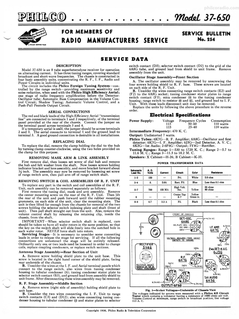
Philco 16 Reference manual

PHILCO
RtO.
U.$.
PAT,
Off.
Price
change
effective
after
Sept.
15,
1933.
Service
Bulletin-No.
165-B
(This
Bulletin
Supersedes
Service
Bulletin
No.
165)
Model
16
TnE
PHILCO
RADIO
MonEL
16
is
an eleven-tube superhetero<lyne broadcast
and
short-wave receiver,
operating upon
alternating
current
and
employing the high-efficiency 6.3 volt tubes, automatic inter-
statiou noise suppression,
and
a frequency (wave-band) coverage
that
permits reception of
the
short-wave
(high-frequency) broadcast programs.
The
same superheterodyne circuit
is
used for all reception.
The
Receiver is equipped with a five-point wave-band switch.
The
ranges
are-
(1) 520 K. C.
to
1500 K. C. (3) 3.2
M.
C.
to
6.0
M.
C.
(2) 1.5
M.
C.
to
4.0
M.
C. (4) 5.8
M.
C.
to
12.0
M.
C.
(5) 11.0 M. C.
to
23.0 M. C.
The
Receiver employs a Philco
Type
77
tube
for first detector, a
Type
76
for oscillator, a
Type
78
for first
I.
F.,
a
Type
78 for second
I.
F.,
and
a
Type
37 for second detector.
The
automatic
interstation
noise suppression circuit uses a
Type
78,
the
first A.
F.,
a
Type
77.
The
driver (second A.
F.)
is a
Type
42;
the
class
"A"
amplification
is
accomplished with two
Type
42 tubes as triodes;
the
rectifier is a
Type
5-Z-3.
The
intermediate frequency
is
460 kilocydes.
The
power consumption of Model 16-122
is
130
watts;
of
Model 16-121, 120
watts.
'fable
1-Tube
Socket
Data*-A.
C. Line Voltage
115
Volts
Inter-
2nd
hi
hi.
2nd
2nd
Station
ht
A.
F.
Rectl·
Circuit
0,1.
01c.
I.F.
I.F.
0,1.
Nol11
A.F.
(Drlv- Output
n,r
Supr. er)
Circuit
----
--
----
--
Type Tube
77
75
78
78
37
78 77
42
42
42
5-Z-3
----
--
----
------
--
Filament
Volts-F
to
F
........
0.3 6.3 6.3 6.3 0.3 0.3
fl.3
6.3 6.3 6.3 4.7
----
--
--
--
--
--
--
--
--
--
Plate
Volts-P
to
K
...........
220 53 225 230 0 1.8 130 220 340 340 400
----
--
--
--
--
--
--
--
--
--
Screen Grid Volt.o-SG
to
K
....
so
-
so
so
-1.8 1.8 220 340
340
-
------
--
--
--
--
--
--
----
Control Grid
Volts-CG
to
K
...
1.0 M 0 0 .2
UI
.4 .6
34
34
-
----
--
----
--
--
--
----
Cathode
Volts-K
to
F
........
4.2 1.9 2.2 2.5 0 0 0 0 0 0 -
• All of
the
above readinl!' were taken from
the
u!1der,i4e of the
cha~111,
ming test prods and leads with a suit-
able
A.
C. voltmeter
for
filament voltages, and a h,gh-re,nstance multi-ran11e D. C. voltmeter
for
other readings.
The
Philco Model 048 All-Purpose Set Tester is highly recommended
for
this use. Volume control set
at
maximum
nnd stn.tion .,eJector
turned
to
low frequency
end;
interstation
noise suppression circuit J><?lentiometer
turned
nil
the way
to
the right: and toggle switch (interstation nmse suppression circuit)
in
"0:,./
..
(''S")
position. Reuding•
taken with a
plu11-in
adapter
will
NOT
be
satisfactory.
NOTE-These
values
arefor Model 16-122.
Model 16-121 uses a
Type
80
Rectifier
Tube.
SeeNote,page
4,
at
end of Replace-
ment
Parts
Li!t.
Table
2-Power
Transformer
Data
TYPE 1-2
TU8E
TY•E4:1.
TUU-fc:==~
n,r.u
TUIE
TYPE 5·1.·3
TVPE
77
TUBE TUBE
TYPri
37
TUIE
TYPE711
TUIE
TYPE70
TU&E
~Fl~.
1-Top
View
of
Chassis,
Showing
Tube Locations
and
Major
Puts
~
~
~~}
Sockets
c-~
78
} Sockets
·ua1
Terminal
1-2
3-5
0-7
8--10
4
9
A.
C.
Volta
Circuit
Color
105-125
Primary
White
6.3 Filament Black
5.0 Filamentof 5-Z-3 Blue
800 Plates of 5-Z-3 Yellow
-Center
Tap
of
3-5
Black-Yellow
Tracer
-Center
Tap
of
8--10
Yellow-Green
Tracer
g
42
Socket
,
~
~
5-Z-3 Soeker
Terminal Arrangement
of
Tub,
Sock1to
Viewed
from
Und1rold1
of
Chassis

1 3 4
I
oO
O S
o~
All
SWITCH
SECTIIMS
SHOWN
IN
,os1TION
1fil
/
/
/
/
/
/
Flt, 2-Schtmatlc Wlrlni Dlairam
J.F.=460
K.C.
GmNlWNIT[
iSrl:fil:f
t},tb.
fJ
,,.
TO
CAN
@
INTERNAL
CONNftTIONS
FILHR
CINIENSER
~ANK
00
(P
"'1
~
-
r:i
(P
c:,
=
-
-
(P
<"1-
.....
::::s
z
0
.
-0
:c
r-
0
0

No.
165-B PH I LCO
Service
Bulletin
Page 3
ANTENNll.
GROUND
Fir.
3-Bottom
View
of
Chassis,
Showin,i
Parts,
and
Position
of
Compensatin&
Condensers
Located
Under
Chassis
~A.
'""·~""-W/1.VETRAP
IST I.F. IITI.F.
~~l'IARY
@@5
.
2••1.R~2•0l.F.
SECONDARY
~
@
PRIMARY
3"DI.F.
)RD
I.F.
SfCONDAA~PRll'IAIW
VOLUME
CONTROL.
AND"
ON·OFF"SWITCH
4
~
3
~
2
~
l
STATION
SELECTOR
H.F.ANT.
L.F.ANT.
RANGE
2.
TOME
CONTROL
Fir.
4-Position
of
CompenutinR
Condensers
Located
Abov"
Chusis
NOTE:
DO
NOT
ATTEMPT
TO
ADJUST
the
compensating
condensers
mounted
upon
sections
3
and
'I
of
the
tuning
condenser.
These
com pcnsatinrr
condensers
are
carefully
adjuste<I,
and
scaled
at
the
factory.
Inability
of
a suitable
radio
receiver
to pick
up
signals
upon
the
shorter
waves
(higher
frequencies)
frequently
can
be
traced
to
the
aerial
itself.
A
relatively
short,
but
efficiently
designed,
aerial
will
give
better
results
on
the
short
wo.ves
than
one
which
has
a Jong
and
involved
lead-in.
Extreme
care
should
be
exercised
in
the
installation
of
the
Model
16,
that
it
may
have
every
opportunity
to
bring
in
all
the
frequencies.
Instruction
should be
given
the
customer
in
tuning
in
the
shorter
waves,
which
are
characteristically
difficult
for
a novice.
Attention
should
be called
to
the
time-difference
existing,
that the listener
may
not
listen
at
such
hours
as a
desired
station
is
n-ot
transmitting.
Much
good will be accomplished
by
a
thorough
instruction
of
the
customer.
Philco
distributors
are
prepared
to
supply
special
aerial
equipment,
especially
designed
for
reception
of
the
short
waves.
ADJUSTING MODEL
16
(Refer
to
Service
Bulletin
No.
16S-A)
These
receivers
are
adjusted
accurately
at
the
factory
prior to shipment.
Under
normal conditions
it
is
not
neccs·
sary
to
readjust
the
compensating
condensers.
If
such
adjustment
becomes
necessary,
it
should
not
be
attempted
without
first
making
sure
that
proper
instructions
and
suitable
equipment
are
at
hand.
Philco
distributors
arc
in
•
position
to
supply
both.
The
Philco Model 048
All-
p,.rpose
Set
Tester
contains
a
variable-frequency
signal
generator
covering
all
frequencies
between 105
K.
C..
and
2000 K. C.,
nnd
is
highly
recommended
for
the
adjust-
ment
of
the intermediate
frequency
compen~atin.R:
con·
<lensers,
and
for the
adjustment
of
those
compensating
condensers
in
the
lower
frequency
circuits. Tlte Philco
Model
091
Siona/
Ge1<erator is recommended
for
the
higher
frequencies.
Refer
to
Service
Bulletin
No.
165-A
for
full-
instructions
upon
the
adjustment
of
Model
16
series.
CAUTION:
The
I.
F.
and
low
frequency
compensating
condensers only should he adjusted in emergencies.
Ex·
treme
care
should be exercised in ~djnsting the JI.
F.
circuits.

Page
4 PH I LCO
Service
Bulletin
No. 165-B
·-··
·-·
REPLACEMENT
PARTS
FOR
·MODEL
16
-
···.
. .
··,·---·-·
No.
on
Lisi
Figs. D11crlptlon · · Part
N·o.
PrlCI
CD
Wave Iland Switch
.............
,
......
.
® Tuning Condenser Assembly
.........
:
..
42-1037 2.75
31-1039 4.50
@ Compensating Condemer
(Wave-trap)
..........
{ Wave-trap } 38
_5199
© Inductance (Wave-trap) . . Assembly
® Condenser . . . . . . . . . . . . . . . . . . . . . . . . . . . . 5858
© Compensating Condenser (Ant.; II. F.;
Part
of@)
.....................................
.
CD
Compensating Condenser (Ant.; Broadcast
and Police;
Part
of @)
..............
.
© Antenna Transformer
(H.F.
Bands)
......
32-1183
© AntennaTransformer (B'dc't &Police B'ds) 32-1182
@ Resistor (Brown-Black-Orange)
..........
4412
@ Compensating Condenser (Range
3)
. . . . . . 04000-V
@ Condenser
............................
30-1000
@ Compensating Condenser (Range 2; series) 04000-R
@ Compensating Condenser (Range
1;
series) 04000-R
@)
Condenser. . . . . . . . . . . . . . . . . . . . . . . . . . . . 3615-L
@ Resistor (Green-Black-Red) . . . . . . . . . . . . . 5310
@ Condenser. . . . . . . . . . . . . . . . . . . . . . . . . . . . 5886
@ Resistor (Brown-Black-Orange)
..........
4412
@ Oscillator Coil
(I-1.
F.)
..................
32-1185
@ Conden~er. . . . . . . . . . . . . . . . . . . . . . . . . . . .
7301
.16
.20
.16
.20
.35
.35
.16
.20
.25
.20
.35
@a
Resistor (Brown-Black-Orange)
..........
4412 .20
® Compensating Condenser
(Rangel;
Shunt) 0-4000-A .12
® Oscillator Coil (Broadcast and Police)
....
32-1184
@ Compensating Condenser (Osc.; H. F.;
Part
of®)
.............................
.
@ Compensating Condenser (Osc.; Police;
Part
of®)
.............................
.
@)
Resistor (Flexible Wire-wound; Green-
Black-Brown). . . . . . . . . . . . . . . . . . . . . . .
6977
@ Condenser. . . . . . . . . . . . . . . . . . . . . . . . . . . . 5863
® Resistor (Green-Brown-Orange)
..........
4237
@ Compensating Cond'ser (1st,
I.
F. Primary) 31-6002
@ 1st, I. F. Transformer. . . . . . . . . . . . . . . . . . 32-1186
@ Compensating Cond'r (1st,
I.
F. Secondary) ~ilim@n
.20
.18
.25
@ Condenser
..
.
..
. . .
..
..
..
. . . .
..
. . . .
..
. 3615-AB .20
@)
Hesistor (Flexible Wire-wound; Orange-
Black-Brown) . . . . . . . . . . . . . . . . . . . . . . . 33-3010
.15
@a
Condenser
............................
3615-BK .16
@ Resistor (Red-Black-Green)
.............
5872 .20
@ Condenser
............................
3615-BL
.16
@ Resistor (Brown-Green-Green) . . . . . . . . . . . 7009 .20
@a
Resistor (White-White-Orange)
..........
4411
.20
@ Resistor (Yellow-White-Yellow).... 4517
.20
® Compensating Cond'ser (2d, I.
F.
Primary) 31-6002 .35
® 2d,
I.
F. Transformer
...................
32-1186
@ Compensating Cond'r (2d,
I.
F.
St"con<lary)
~ilim@)n
@ Condenser
............................
3615-BK
.16
@ Resistor (Flexible Wire-wound; Orange-
Black-Brown) . . . . . . . . . . . . . . . . . . . . . . . 33-3010
@)
Pilot Lamp (Station Selector)
............
6608
@)
Shadow Tuning Meter. . . . . . . . . . . . . . . . . .
6497
@)
Pilot Lamp (Shadow Tuning Meter;
Part
of@))
.............................
.
.15
.12
2.25
@ Compensating Cond',er (3d,
I.
F. Primary) 31-6003 .35
@ 3d,
I.
F. Transformer
...................
32-1188
,k~
~
·
Fl11.
· D11crlption Part
No.
Prlc1
@.
Compensating Cond'r (3d,
I.
F. Secondary) ~ilim@n
@ Condenser
.............................
3615-AS .25
@ Resistor (Part of @)
......
: .
..........
.
@)
Hesistor (White-White-Orange)
..........
4411
® Condenser
............................
4519
@a
Condenser
............................
4519
@)
Condenser (Double) . . . . . . . . . . . . . . . . . . . . 7296-G
@)
Resistor (Yellow-Black-Green)
..........
6010
@ Switch (Toggle); lnterstation Noise Sup-
pression Circuit. . . . .. . . . . . . . . . . . . . . . . 3253
@ Volume Control
and
"On-Off" Switch
....
33-5022
.20
.18
.18
.20
.40
@)
Resistor (Orange-Red-Orange) . . . . . . . . . 5279 .
20
@a
Resistor
:orange-Orange-Yellow)
.....
6046 .20
® Condenser . . .
..
. .
..
. . . . .
..
. . . .
..
.
..
..
. 3903-J .20
@)a
Condenser
...........................
3903-J
.20
@)
Condenser . . . . . . . . . . . . . . . . . . . . . . . . . . . . 4519 .18
@)
Condenser . . . . . . . . . . . . . . . . . . . . . . . . . . . . 3615-AD .
20
@)
Resistor (White-White-Orange)
..........
4411
.20
® R.esistor (Violet-Black-Orange) . . . . . . . . . . 5385 .20
@)
Filter Condenser Bank. . . . . . . . . . . . . . . . . 30-4026 3.00
@)
Resistor (Brown-Blue-Yellow)
...........
5331 .20
@ Resistor (White-White-Orange) . . . . . . . . . .
4411
.20
@)
Condenser (Double)
...................
6287-J
@
Input
Transformer
.....................
32-7057
2.25
@)
Resistor (Brown-Black-Orange) . . . . . . . . . . 3524 .
20
@)
Condenser . . . . . . . . . . . . . . . . . . . . . . . . . . . . 3903-F .
15
@)
Output
Transformer
...................
32-7052
1.50
@)
Voice
Coil and Cone
A!.!<embly
..........
36-3061 .
75
@ Speaker Field, Assembled with
Pot
(U-2). . 36-3088
@ Resistor (Brown-Black-Green)
..........
4409
@ Resistor (Wire-wound) . . . . . . . . . . . . . . . . . 33-3020
@ Resistor (Brown-Black-Green)
...........
4409
@ Condenser (Electrolytic) . . . . . . . . . . . . . . . 30-2003
® Resistor (Yellow-White-Yellow)
.........
4517
@ Condenser (Internal to.@)
.........
·
....
.
@ Tone Control . . . . . . . . . . . . . . . . . . . . . . . . . 30-4069
@)
Condensers (External to @) . . . . . .. . . .. . 7653-C
@ Voltage Divider Resistor (Wire-wound)
...
33-3021
@)
·Potentiometer (lnterstation Noise Suppres-
sion Circuit)
........................
33-5015
@)
Resistor (Brown-Black-Orange)
..........
3524
.20
.30
.20
.70
.20
.16
.80
.20
@ Resistor (Brown-Orange-Orange)
........
6450 .35
@)
Filter Choke
..........................
32-7056
l.
85
@ Condenser
............................
6287-F .12
® Condenser (Electrolytic). . . . . . . . . . . . . . . . 30-2011 1.
25
@ Condenser (Electrolytic) . . . . . . . . . . . . . . . . 30-2011 1.
25
@)
Power Transformer (50-60.--)
...........
32-7058 5.
00
@ Condenser (Double). . . . . . . . . . . . . . . . . . . . 3793-E .
20
® Resistor (Brown-Green-Orange) . . . . . . . . . 5718 .
40
Speaker
Socket.
. . . . . . . . . . . . . . . . . . . . 4957 .08
Tube Shield
..........................
28-1107 .10
Four-prong Socket.
....................
7545 .08
Five-prong Socket.
....................
7546
.10
Six-prong Socket
......................
7547 .10
Knob
(Large)
......................
27-4025
Knob (11:cdiurn)
......................
03063 .08
Knob (Small)
..
. . . .
....
.
.. .. ..
. .
..
. . . . 03064 .
06
NOTE.-Model
16-121
uses
a
Type
SO
tube
in
lieu
of
5-Z-3.
Parts
used
in
the
16-121
chassis
that
differ
from
the
16-122
parts
above
listed
are:
@)
PowerTransformer(50-60.--)
...........
32-7080
4.50
Speaker
..............................
K-17
® Condenser (Electrolytic)
(8.0
Mfd.)
......
6706 1.50 Speaker Socket
Hole
Cover
............
7084
.75per
C
@ Condenser (Electrolytic)
(8.0
Mfd.)
......
746-1
1.25
Speaker Cable
........................
L1632 .20
USE
PHILCO
REPLACEMENT
PARTS
AND
TUBES
FOR
EVERY
MAKE
RADIO.
GET
COMPLETE
CATALOG
FROM
YOUR
DISTRIBUTOR.
PHILCO
RADIO & TELEVISION CORPORATION
Septemller
1033
Printed in
U.
S.
A.
Service
Department
Sec. 1
"Cose
Histories"
of
Receiver Troubles
and
their
Remedies
PHILCO
14X,
14LZX-(Cont'd)
Inoperative
__
1)
failure
or
"open"
circuit
in
shadowcraph
(shadowcraph
(connected
in
"B"-plus
circuit
of
the
r-f
does
not
and
i-f
tubes
operate)
Intermittent
______
1)
snapped
coil
leads
at
lugs
of
01cillator
reception
coil
Insufficient
________
1)
small
antenna.
Increase
size of
antenna
shadowgraph
2)
weak
type
'44
tubes
in
r-f
and
i-f
stages
action
3)
increase
value
of
diode
detector
sec-
ondary-return
resistor
Shadowgraph
____
l)
receiver
circuits·
out
of
alignment
inoperative
on2)
defective
type
'6A7
tube
local
stations
No
control
of
____
1)
check
type
'37
tube
in
first
audio
stare
tone
Signal
drift
_____
1)
after
set
is
turned
on,
the
tuninr
of
the
station
"creeps"
for
as
long
as
30
to
60
minutes.
Replace
tension
spring
on
back
of
gang
condenser-use
new
type
Philco
spring
(part
No. 77760)
(
due
to
dial-
cueping)
Noisy
volume
___
1)
disconnect
end
of
control
that
goes
to
detector
and
from
this
detector
lead
con-
nect
a 300,000-ohm
%-watt
resistor
to
ground.
Also
from
this
lead
bridge
a
0.05
or
0.06-mfd. con.denser
to
the
dis-
connected
end
of
the
volume control.
This
removes
the
d-c
from
the
volume con-
trol
and
permits
quiet
operation
control
(
installing
a
new
control
only
a
tem-
porary
cure)
Motorboatinr
____
l)
eliminate
by
connecting
100,000-ohm
re-
1i1tor
from
first
audio
grid
to
chassis
sound,
Hum
Broad
tuninr
_____
i)
r-f
and
i-f
compensating
condensers
out
of
alignment
Whistling
__________
l)
compensating
condensers
out
of
adjust-
ment
2) move all
leads
adjacent
to
01cillator coil
further
away
from
it.
PHILCO
CT-14
Auto
Radio
Weak
reception
__
})
check
alignment-especially
of
antenna
1tction
of
tuning
gang.
To
improve
per-
formance,
move
the
lead
that
goes
from
~rst
grid
section of
gang
to
the
coil
away
from
all
other
leads
and
the
chassis
PHILCO
TH-14
lfodulation
hum
__
})
replace
conuenser
No.
1!
with
a ~-mfd.
at
hi,:h
volume
electrolytic
unit
PHILCO
15
Inoperative
________
l)
tuning
meter
No.
37
"open"
(indicated
by
narrow
shadow)
2) check
condenser
No.
13
(0.25-mfd.)
from
first
detector
plate
return
to
,:round
for
breakdown
3)
check
condenser
No.
16
(0.05-mfd.)
from
first
i-f
plate
return
to
ground
for
break-
down
(3-mfd., 0.5-mfd., 1-0.015-mfd.,
and
1-
1-mfd.)
4)
check filter
condenser
block No.
3S
5)
"open"
primary
of
input
transformer
No.
56
~) check No.
25,
couplin~
condenser
con-
nected
from
oscillator
plate
to
coil
(Cont'd)
PHILCO
15-(Co11t'c)
Intermittent
--1)
replace
the
200-ohm
oscillator
cathode
reception
resistor
and
the
0.09-mfd.
by-pass
con-
denser.
Use
a 0.1-mfd.
condenser
to
re-
place
the
odd-size 0.09-mfd.
unit
2)
replace
coupling
condensers
No. 44
and
No. 49 (0.01-mfd.
each)
in
first
and
second
a-f
stages.
Although
these
con-
densers
may
test
O.K.
it
is
best
to
re-
place
them
Distortion,
_________
})
connect a 0.25-rneg.
resistor
acro11
the
normal
volume control,
and
a 0.002-mfd.
condenser
between
the
plates
of
the
power
tubes
Weak,
"tinny"
at
hirh
volume
2) check condensers No. 48
(twin
0.25-mfd.)
for
breakdown.
Common
ground.
Ont
goes to
filter
resistor
of
first
audio
plate
supply,
the
other
to
filter
resistor
of
all
audio
grid
biases
3)
bn,akdown
in filter condenser block
No.
33
between
sectio11s.
Capacities
3-0.5-
mf
d.,
1-0.015-mfd.,
1-1-mfd.
4)
check
push-pull
input
transformer
No.
56
for
breakdown
(indicated
by
"fryin~"
noise)
Audio
whistle
----1)
replace
both
'47
push-pull
output
tt1b11
check
for
loose shield
cans
on
r-f
and
i-f
transfort.:.ers
Squealing,
--------1)
Noise.
Squealing
------1)
(intermittent
and
steady)
replace
condenser
No.
12
(0.09-mfd. con-
denser)
from
screens
to
ground.
Con-
denser
may
test
O.K.
but
may
be
inter-
No
:r;ero
Yolume
__
at
any
setting
of
volume
control
mittently
"open"
.
2)
replace
condenser
No.
13,
-(0.25-mfd.)
from
first
detector
plate
returns
to
ground.
Condenser
may
test
O.K.
but
may
be
intermittently
"open"
3)
replace
condenser
No.
31
(0.05-mfd.)
from
first
i-f
AVC
filter
resistor
to
ground.
Condenser
may
test
0.K.
but
may
be
intermittently
"open"
4)
replace
condenser
No. 26 (0.06-mfd.)
first
i-f
plate
return
to
ground.
Con-
denser
may
test
O.K.
but
may
be
inter-
mittently
"open"
"open"
A
VC
Condenser
No. 42 (0.00011-
mfd.)
connected
from
volume
control
to
rround
"Shadowgraph"
--1)
does
not
indi-
cate
on
weak
signals
replace
first
detector
and
i-f
tubes
Tuninr
con-
______
l)
faulty
spring
used
to
hold
drive
cable
under
tension.
Replace
with
imprond
spring
(part
No.
7776)
denser
slip-
pinr
PHILCO
16,
UB,
16X, 16RX-(C-O<l.es 121, 122)
Inoperatin
_______
l)
open
circuit
in
tuning
meter
No. 48
2) check
condenser
block No. 62. Common
goes
to
Cc:'.n;
condenser
A
(2-mfd.)
to os-
cillator
plate
filter
resistor;
condenser
B
to
tuning
metet';
condenser
C (0.6-
mfd.)
to
first
a-f
plate
supply
filter
re-
sistor;
condenser
D (0.5-mfd.)
to
screen
supply
of
first
a-f
tube;
condenser
E
(1-
mfd.)
to
screen
grid
supply
of
first
de-
tector
and
i-f
tubes
3)
check
condenser
No. 94 (0.05-mfd.)
from
first
detector
and
first
i-f
plate
supply
to
ground.
Faulty
condenser
here
indi-
cated
by
narrow
shadow
on
tuning
meter
4) check
for
breakdown
between
Hctions
of
condenser
black
No.
62. (Capaciti11
2-2-mfd.,
2-0.5-mfd.,
1-1-mfd.)
(Cont'd
over)
153

11
Case Histories
11
of
Receiver Troubles and their Remedies Sec. 1
PHILCO 1,,
1'B,
1'X,
1'RX-(Cod•
1%1,
12%)-(Ce,it'i)
Inoperatin
___
1)
wire
from
first
section
of
tuning
con-
(r-f
dead, f-f
denser
pulled too
tight
and
grounding
O.K.)
against
chassis
Inoperative
-------1)
(no
i-fj
high-voltage lead (
black
wire)
from
i-f
transformer
(first
facing
front
of
chassis) grounded.
This
does
not
effect
audio
2)
compensators in
top
of
i-f
can
grounded
to
can
Inoperative,
___
l)
Low !emsitivity
(possibly
short
wave
recep-
tion
comes
in
on
broad-
cast
band
setting)
check
contacts
on
band
switch.
These
contacts
may
shift
or
drop
out
complete-
ly.
This
m1:1.y
be
indicated
by
short
wave reception on
the
broadcast
band,
and
by
improper
tracking
of
the
oscil-
lator
check
for
intermittently
"open"
0.003-
mfd. condenser
No.
£0
Inoperative
at
__
l)
low
end
of
short-wave 2) check
for
intermittently
"open"
0.0007-
mfd. condenser connected
to
76
tube
band
Inoperative
_____
.:._1)
from
11
to
26 me.
Inoperative
be-
..
1)
, low 15
me
replace
condenser
from
lug
1 on
bottom
of
waveband
switch
to
ground
marked
with
orange
and
yellow
dots
with
one
of
the
"lug"
type
(value
700-mmfd.).
A
poor
connection
internally
in
the
pig-
tail
condenser stops oscillation
high
resistance
tuning
condenser
gang
rotor
contacts. Bond
rotor
to
tuning
condenser
frame
with
flexible
wire
pig-
tails
2)
tighten
screw
holding
the
bottom solder-
ing
lug
to
the
tuning
assembly
lnoperafr,e
at
___
1)
if
this
is due
to
failure
of 76
oscillator
to
function
at
the
high
frequencies,
first
try
a
new
76
oscillator
tube.
If
this
does
not
help,
change
the
500-ohm oscillator
cathode
resistor
to
a 300-ohm
unit
hich-freq.
end
of
broad-
cast
band
Intermittent
---1)
reception
(Tolume
drops
"open"
250-ohm
resistor
in
plate
circuit
of second
i-f
stage.
This
resistor
is
con-
tained
within
the
case
of
the
small
black
bakelite
condenur
for
this
stace
and
is
located
adjacent
to
the
2nd
i-f socket
to
very
low
level,
no
plate
voltage
on i-f 78
tube,
and
,:,:
..
"shadow-
..
, z-raph"
indi-
cation
wid-
ens)
Intermittent
____
l)
check 0.01-mfd.
tubular
audio diode-
coupling condenser connected between
bottom
terminal
of
volume
control
and
the
junction
of
the
two
diode load
re-
sistors
reception
(shadow-
.,
-·"~aph
oper-
atH
normal-
ly-)
2)
replace volume
control
3)
faulty
78
tube
(even
though
it
checks
O.K.)
4) replace coupling condenser
No.
59
(0.05-
mfd.) connected
from
first
a-f
to
second
a-f
tubes
5) check
transformer
No.
46
Intermittent
__
1)
reception,
check compensator condensers
No.
30,
39, 45 located
in
first, second
and
third
i-f
transformer
cans.
Fault
may
be
due
to
loose
rivets
or
dirt
between
plates.
Tap
cans
to
locate
trouble,
and
replace
assembly
Low 1en1itivity
(Cont'd)
154
PHILCO
1,,
1'B,
1,x,
URX-(Codes
121,
1%%)-(Cont'li)
Bass
distortion
-1)
(
treble
harsh)
(77
first
det.
and
two
i-f
check
for
reduction
in
value
of
10,000-
ohm
resistor
No.
83 connected
in
network
between noise
potentiometer
and
No.
91
15,000-ohm
resistor.
Replace
with
20-
w~tt
wire-wound
resistor.
Realign
re-
ceiver
78
screen
voltages
above
normal
after
set
warms
up)
Distortion
at
______
l)
replace 0.05-mfd. first
to
second
stare
low
volume
audio coupling condenser
No.
51
2)
check 10-mfd. electrolytic condenser No.
7S connected
from
high
voltage center-
tap
to
chassis
Distortion
at
___
l)
hich
volume,
Weak
"tinny-"
sirnal
check
for
breakdown
between sections of
condenser block
No.
62
(capacities
2-2-
mfd.,
2-0.05-mfd.,
1-1-mfd.)
Distortion
and
....
1)
check
grid-bias
voltage
for
the
driver
Hum
and
output
stages.
Lack
of
normal
bias
on
either
of
these
stages
usually
results
in
the
control
grids
of
the
42 tubes glow-
ing
red
(a
low-emission 42
tube
will
produce
the
same
result)
. Check
for
a
"leaky"
or
"shorted"
0.15-mfd.
grid
filter
?Y-pass con~ens~r
in
the
driver
stage
2)
1f
control-grid
bias
on 42
tubes
is low
or
absent,
check
secondary
return
of
push-pull
input
transformer
for
ground-
mg
to
the
case
or
the
laminations
of
the
transformer
internally.
Replace
trans-
former
3)
l.akage
of
the
paper
which
is
supposed
to
insulate
the
electrolytic
filter
con-
denser
from
the
chassis.
Either
one,
or
both, condensers
must
usually
be replac-
ed
4)
"leaky"
electrolytic condenser
No.
75. Re-
place
with
new
unit
Weak,
choked
----1)
reception
check
screen-grid
voltage
applied
to
77
first
a.f
tube
(should be
approximately
50
volts).
If
off,
replace
the
1-meg.
car-
bon
resistor
which
supplies
this
voltage
(with
tb
noise
sup-
pressor
tube
in
or
out
of
the
circuit)
How
to
tell
_______
1)
difference
b.-
tween
"fad-
ing"
and
"fre-
quency
drift"
Fa.dine
----------------1)
(
condensers
and
resistors
check
O.K.)
Fadinc-
--------1)
in all
cases
of
"apparent
fading"
of
sig-
nal,
shift
1·eceiver
tuning
5
or
10 kc plus
-then
minus.
If
this
restores
the
sig-
n~!,
the
trouble
is
not
due
to
fading
but
to
frequency
drift
which
has
occur-
red in some
part
of
the
receiver
(com-
mon causes
and
remedies
for
frequency
drift
in
various
models
of
receivers
list-
ed
further
on)
intermittent
open-circuit
in
the
third
i-f
transformer.
Replace
with
new
unit
if
defective
bakelite which holds
stator
of
oscillator
tuning
condenser
expands
or
contracts,
allowing set-screws
and
rivets
to
loosen.
This
causes
stator
to
shift
its
position
slightly
thereby
changing
the
oscillator
frequency. Remove
gang
condenser
and
tii-hten all
set-screws
and
rivets.
Realign
receiver
Intermittent
__
l)
secondary
of
first
r-f
transformer
has
fadinr
hirli-rHi1tance
connection (Cont'd}.

Sec. 1 "Case Histories••
of
Receiver Troubles and their Remedies
PHILCO
1',
1'B,
1'X,
1'RX-(CodH
1%1,
12Z)-(Co11t',f)
Fadinc
on
_______
1)
variable
tuning
condenser
imperfectly
crounded
to
chassis.
Bond
condenser
frame
to
chassis
with
heavy
flexible
pig-
tails
which
will
not
interfere
with
"float-
ing"
mounting
•hort-waye
bands
Oscillator
drift
2)
clean
the
rotor-shaft
contacts
S)
.tighten
all
screws
on
gang
condenser,
and
between
gang
condenser
and
chassis
4)
waveband
switch
not
grounded
perfect-
ly.
Ground
frame
of
waveband
switch
to
chassis
with
pigtails
5)
replace
fibre
insulator
on
high-frequency
compensating
condenser
with
new
and
thicker
type
Frequency
_________
l)
in
order
to
alleviate
frequency
drift
it
is
recommended
that
the
first
and
second
i-f
transformers
be
replaced
with
part
No.
32-1186,
using
compensating
con-
denser
assemblies
(Part
No.
91-6090),
with
shunt
condensers,
(Part
No.
30-1086)
connected
across
both
the
pri-
mary
and
secondary
sections.
The
third
i-f
transformer
should
be
replaced
with
Part
No.
31-1866
using
compensating
condenser
assembly
(Part
No.
31-6003),
no
shunt
condensers
being
used
drift
(due
to
i-f
drift)
Frequency
_______
l)
drift
(
due
to
dial-
creepinl')
Volume
un-
______
l)
controlled
Code
inter-
------1)
ference
Whi:stlinc
or
______
1)
1quealinc
(intermit-
replace
tension
spring
on
back
of
gang
condenser
-using
improved
Part
No.
77760
if
at
zero
volume
control
setting
and
with
the
QAVC
switch
in
the
S
position
the
volume
does
not
reach
minimum
or
zero,
replace
the
0.02-mfd.
condenser
in
the
78
QAVC
control-grid
circuit
with
a 0.01-mfd.
condenser
readjust
wave
trap
for
minimum
inter-
ference.
In
extreme
cases,
reduce
the
i-f
to
a
lower
value-say
440 kc.
The
high
and
low
frequency
compensating
condensers
of
the
oscillator
circuit
:should
be
readjusted
in
order
to
repro-
duce
the
correct
i-f
if
accompanied
by
.image
signal
check
0.05-mfd.
condenser
No.
15
for
"open."
Connected
from
first
detector
grid
re-
turn
to
ground
tently
or
:steady)
2)
check
0.05-mfd.
condenser
No.
48
from
second
i-f
plate
supply
filter
resistor
to
cround
3)
solder
pigtails
from
all
r-f,
i-f
and
oscil-
lator
transformer
shield
cans
to
ground
replace
loose
tuning
meter
bracket
4)
Hum
---·
----------1)
(in
early
replace
the
a-c
switch
jumper
from
switch
through
terminal
lug
mounted
on
condenser
at
back
of
set
with
shielded
wire
(with
the
shield
grounded)
:series)
Hum
----·--·--------1)
check
for
"open"
0.3-mfd.
condenser
No.
16
connected
across
filter
choke
Tone
impron-----1)
connect
a 0.006-mfd_ 400-volt
tubular
rnent
condenser
from
the
77
tube
plate
to
the
(
early
models)
tone-control
connection
Two
resonance
--1)
replace
shadowgraph
with
improved
part
peaks
indicat-
number
45-2021
ed
on
shadow-
graph,
Widening
of
shadow
upon
r•sonance
(Cont'd)
PHILCO
1',
1'B,
1,x,
1,RX-(Codea
121,
122)-(Cont'tl)
Choked
-----1)
open-circuited
2-mfd.
by-pass
condenser
B
in
condenser
block
2)
open-circuited
0.5-mfd.
first
audio
plate
by-pass
condenser
Noisy
reception
1)
defective
shadowgraph
bracket.
Replace
Motorboating
----1) check
for
"open"
section
in
condenser
sound
block No.
62
(capacitiH
2-2-mfd., 2-0.06-
(steady
or
in-
mfd.,
1-1-mfd.)
termittent)
PHILCO
16, 16-X, 16-RX
(Code
123)
See
also
the
Case
Histories
listed
for
Philco
1~
(Codes
121
and
122)
receivers
Inoperative
on
-.1)
high-resistance
contacts
in
waveband
S-W
band
switch.
Replace
wtih
new
switch
Intermittent
______
1)
intermittent
connection
between
coil
reception
lead
and
hook-up
wire
in
third
i-f
trans-
former
PHILCO
1',
16B, 16X
(Codes
125, 126)
Inoperative
______
l)
replace
0.05-mfd.
condenser
No.
!%
con-
n•cted
from
filter
resistor
of
r-f
ampli-
fier
plate
supply
to
ground
(open
shadow
on
tuning
meter)
2)
replace
twin
0.05-mfd.
condensers
No. 15
connected
from
each
side
of
shado-.r-
graph
to
ground
(open
shadow
on
tun-
ing
meter)
3)
check
1-mfd.
condenser
No-
79
connect-
ed
from
screen
grid
of
77
first
audio
tube
to
ground
•
4)
check
0.05-mfd.
condenser
No.
SI
con-
nected
from
filter
resistor
of
second
i-f
plate
supply
to
ground
5)
cheek
0.25-mfd.
condenser
No.
It
con-
nected
from
filter
resistor
of
first
audio
plate
supply
to
ground
Inoperative,
______
l)
check
contacts
on
band
switch.
These
contacts
may
shift
or
drop
out
complete-
ly.
(This
condition
may
be
indicated
by
Weak
reception
short
wave
reception
coming
in
on
the
broadcast
band
setting,
and
by
improper
tracking
of
the
oscillator)
Weak
nception
_})
check 0.003-mfd.
condenser
No.
11
con-
nected
from
ave
load
resistor
of
first
r-f
tube
to
ground.
Breakdown
indicated
by
inability
to
peak
on
broadcast
band
pad-
der
2)
check
for
"gassy"
5Z3
tube
Weak
reception._
1)
(intermit-
tently)
Weak
reception.
1)
No
plate
volt-
age
on
second
i-f
tube,
Wide
shadow-
graph
indica-
tion
Intermittent
_l)
reception,
check
compensating
condensers
No
. .JI
(first
i-f
primary),
No.
49
(second
i-f
primary),
No. 55
(third
i-f
primary).
Tapping
the
i-f
transformer
cans
will
usually
indicate
intermittent
condenser.
Replace
faulty
one
open-circuited
500-ohm
wire-wound
pig-
tail
type
second
i-f
tube
cathode
bias
rui:stor
open-circuitin~
0-06-mfd. cond•n:ser
con·
nected
between
the
junction
of
the
two
diode
load
resisto1·s
and
the
bottom
lur
of
the
volume
control
·
Very
weak
sig-
nals
(shadow-
graph
operates)
2)
open-circuiting
by-pass
condenser.
Trou-
ble
in
lead
contacts
3)
open-circuiting
250-ohm
resistor
a11em-
bly
blocks
in
i-f
plate
circuit
(Cont'd over)
155

11
Case
Histories'~
of
Receiver Troubles
and
their
Remedies Sec. 1
PHILCO
1',
168,
HiX
(Codes 1!5,
1!6)-(Cont'tl)
Distorted,
_________
l)
open-circuiting,
or
change
of
resistance
of
first
audio
tube
1-megohm
screen
re-
sistor
Intermittent
reception
2)
replace
0.05-mfd.
coupling
condenser
No.
75
connected between
first
and
sec-
ond audio
tubes
Distortion
at
_____
l)
breakdown
in
0.05-mfd.
coupling
con-
low Yolume
denser
No.
75 connected
between
first
and
second
audio
stages
Distortion
at
______
l)
"open"
0.25-mfd.
filter
condenser
No.
82
connected
in
plate
supply
circuit
of
77
hich
Yolume,
Weak
"tinny"
sicnals
first
audio
amplifier
'
Distortion
_______
l)
center-tap
of
push-pull
input
transform-
er
grounded
to
core
or
can
(Insulate
from
chassis
with
insulating
bushings
and
washers)
(crids
of
42
tubes
get
red
hot)
Distortion
_________
l)
leakage
between
insulation
and
chassis
of
first
filter
condenser
(screens
of
42
tubes
get
red
hot)
Whistling
or
_____
l)
insert
a 700-ohm
1-watt
carbon
resistor
in
series
with
the
plate
lead
of
the
78
r-f
tube,
and
remove
the
condenser
shown in
the
circuit
diagram
as
No.
2A
squealing
2)
check
for
"open"
twin
0.05-mfd. conden-
sers
No.
25.
These
are
connected
with
their
"common"
to
ground,
one
to
each
side
of
tuning
meter
3)
check
twin
0.0001-mfd. condensers
No.
61.-These
are
connected
with
their
"com-
mon"
to
ground,
one on
each
side
of
the
second
detector
grid
return
load
re-
sistor
4)
solder
pigtails
from
coil-mounting
screws
of
r-f,
oscillator
and
i-f
trans-
former
shield
cans
to
ground
lfotorboatinr
....
1)
check electrolytic
condenser
block No.
sound
rs,
red,
blue
and
blue 1-mfd. each,
plain
2-mfd. Common
negative
connects
to
can
Hum
_________________
l)
Hum
(intermit-
..
1)
tently)
check
for
"open"
0.3-mfd.
condenser
No.
97,
connected
across
filter
choke
check
for
"open"
8-mfd. electrolytic filter
condenser
No.
91
Dial sticks,
__
l)
excessive
pressure
exerted
by
felt
rests
Dial slipa
against
dial
2)
dial cable
worn
or
frayed
PHILCO
TH·U
Carrier
hum
_____
l)
replace
condenser
No.
lt
with
a 4-mfd.
at
hirh
electrolytic
unit
Yolume
PHILCO
17
SH
also Case
Histories
listed
for
Philco 15
Inoperatin
____
l)
check
for
"shorted"
0.05-mfd. condenser
No.
21
connected
from
oscillittor 11crHn
grid
to
ground
2)
"open"
tuning
meter
No.
ti
(indicated
by
narrow
shadow)
Inoperatin
with
1)
Yolume
con-
trol
at
mini-
mum
settinc
and
QAVC
switch
at
"on"
156
replace condenser 6 (
circuit
diacram)
with
a
O.Ol-mfd-0.002-mfd.
unit
(Cont'd)
PHILCO
17-{Cont'tl)
Intermittent
__
l)
check
for
"open"
first
audio
screen re-
reception,
sistor
Distortion
2)
check
for
increased
value
in
first
audio
1creen
resistor
3)
check
for
faulty
by-pass
condenser
in
rrid-return
of
oscillator
coil
4)
Intermittent
-----1)
reception,
check
for
faulty
r-f
transformer
check
the
2-mfd. section
of
the
filter con-
denser
block
by-passing
large
7,500-ohm
Cho
kine
wire-wound bleeder
resistor
2)
check
the
0.5-mfd.
condenser
units
by-
passing
the
70,000-ohm
resistor
in
the
1st
audio
plate
circuit.
They
are
mark-
ed B
and
C, respectively
Weak
reception
1)
cassy
type
'5Z3
tube
Choked,
__________
1)
1-meg.
carbon
resistor
in
the
plate
and
screen-grid
circuits
of
the
silencing
and
lit
a-f
tubes
has
increased
in
value,
thus
lowering
the
screen-grid
voltage
of
I::;t
a-f
tube
almost
to
the
cut-off point
Distorted
reception
Distortion,
___
l)
secondary
return
of
push-pull
input
transformer
grounded
to
metal
case or
laminations
internally
Hum
(
control-grids
of
output
42
2)
tubes
glow
leakage
between
electrolytic
filter con-
denser
cans
and
chassis-due
to
seepage
and
formation
of
oxides
at
the
bases of
the
condensers
red)
Hum
-----------------1)
(stronc
and
steady)
check
for
"open"
condenser
connected
across
speaker
field
Whistling
---------1)
(
intermittent
check
for
"open"
0.05-mfd. condenser
No.
21
connected
from
oscillator
screen
grid
to
ground
or
steady)
Apparent
_________
l)
check
for
loose
rivets
which
hold the
bakelite
insulating
panels
in
the
sides
of
the
tuning
condenser
sections, permit-
ting
the
statprs
to
shift
"fading"
due
to
freqµency
drift
in
receiver
PHILCO
17-X
Distortion,
____
1)
1st
tilter
condenser leakai-e between in-
sulation
and
chassis
Type
'42
1creens
get
red
hot
Hum
------------------1
)
(stronc
and
steady)
check
for
"open"
condenser
connected
across
speaker
field
PHILCO
18
(Codes 122, 123)
Inoperatin
__
l)
control
grid
of
type
'75
tube
shortinr
to shield
can
2)
open-circuited
audio
coupling-condenser I
3)
"aborted"
tone
control
condenser
4)
check
first
i-f
primary
for
"open"
or
high-resistance
joints
5)
check AVC
coupling
condenser
for
"open"
or
"intermittent"
joint
6)
check
for
"shorted"
0.05-mfd. condenser
No.
12
connected
from
tuning
to
ground
(wide
shadow)
7) check
for
"shorted"
electrolytic
filter
condenser No.
40
(capacities
2-1-mfd.,
1-2-mfd.
(narrow
shadow)
8)
check
for
"open"
tuning
meter
'No. 63
(narrow
shadow)
.
9)
check
for
"shorted"
0.05-mfd. condenser
No.
20
connected
from
6A
7
tube
space
charge
grid
supply
filter
resistor
to
cround
10)
check
for
"shorted"
· 0.006-mfd. con-
denser
No.
4~
connected
from
plate
of
42
flrat
i-f
tube
to
ground
11)
check
for
"open"
primary
in
input
transformer
No.
41 (Cont'd)
Table of contents
Other Philco Radio manuals