Philco 37-116 User manual

• • • • • • • • • • • • • • ?rl.odRl37-116
FOR MEMBERSOF
RADIOMANUFACTURERSSERVICE SERVICEBULLETIN
No. 158
Model 37-116-Codes lZl-lZZ
Electrical Specifications
Type Circuit: Superheterodyne, with magnetic tuning ; Fidelity -
Selectivity control in the intermediate frequency circuit and
pushpull c!ass "A" audio output. The Code 122 Recejver uses
the Philco Automatic Dial tuning system.
Power Supply: 115 Volts A.C. 50 to 60 cycles. For 25 to 40 cycle
operation use power transformer listed in the parts list for this
purpose.
Power Consumption: 165 Watts.
Intermediate Frequency: 470 K. C.
Undistorted Output: 15 Watts.
Philco Tubes Used: 4--6K7G; 3-6J5G; 1-6L7G; 1-6N7G;
1-6A8G; 1-6H6G ; 2-6B4G; 1-6F6G; 1-5U4G.
Tuning Ranges: Fiv,e. Range 1-530 to 1600 K.C .; Range 2-
1.58 to 4.75 M.C.; Range 3-4.7 to 7.4 M.C.; Range 4--7.35 to
11.6 M.C.; Range 5- 11.5 to 18.2 M.C.
Speaker: "W" High-Fidelity Cathedral type.
Precaution
DO NOT APPLY POWER TO THE RECEIVER WITH THE
SPEAKER BNIT DISCONNECTED
Replacing Dial Control Screws
REMOVING CONTROL SCREWS
Code 122
A. First remove the tuning knobs, then detach the metal plate,
covering the control handle by removing the three screws in the
center of the plate.
B. When the metal cover is removed, two screws will be noted
holding the indexing handle to the rotary hub. Remove these
screws and detach the handle. See Fig. 1.
C. Referring to Fig. 1, five screws will be seen which hold the
dial escutcheon to the dial body. Remove these screws and lift the
escutcheon from the dial body .
D. After removing the dial cover insert a screw-driver blade into
the control (indexing) screw, then push in and turn the control screw
until the indexing pin on the side end of the screw is centered in the
small semi-circular slot on the housing adjacent to the hole. When
the screw is in this position release the tension on the screw-driver
and lift the screw from the hole.
NOTE: It may be necessary to move the screw slightly to the
right or left to mesh the teeth on the screw with those in the screw
hole. REPLACING THE CONTROL·SCREWS
A. Insert the control screw in the screw hole. After it is inserted
press the screw in and turn it 18<1degrees, until the stop on the side
of the screw will be in a position to clear the stopping shoulder in the
dial cover hole of this screw. When the screw is in position replace
the dial escutcheon and Indexing Handle.
REPLACING THE DIAL OR MASK ARM ASSEMBLY
Code 122
To replace the dial or mask arm assembly, remove the chassis from
the cabinet . Then remove the tuning knobs, indexing handle ,
handle cover and dial cover as given in the procedure for the removal
of the indexing screw.
DIAL
COYER
SCREW
HANDLE
SCREW
Fig. 1-Automatlc Tuning Dial, Code 122, Receiver-
With these parts removed the scale may be lifted from the dial
housing. MASK ASSEMBLY
Code 122
The removal of the mask and arm assembly necessitates the
removal of the twp fibre and one metal rings around the outer edge
of the dial housing. The mask arm can then be slipped off. Care
should be taken on replacing the metal ring to have the sprin1t
located along the bottom edge of the ring in position, otherwise the
mask will vibrate.
©
®
R£CTIFIER
SU4G
c::;}')
RCCTIF/£/6oi:Kfr,, ~OIIN1"£P
(}Ji TOP orl'OWClf T"RANlJ.
OSC.PLATE-1201/.
OSC.GRl
SCREEN·t:!~V.
SCREEN-84\/ .
,--------·······-·················-·-··-! ~---s._ sv_.-A_.c.._-~_.,.._=_'-_-'.'._--!
6.3V.-A.C
I -
LATE--zqo'-1. lOY.-GRIO~
s;~;~~;;:~:qoK
6.3V.-A.C.
111.I.F.
6K1G 63\L·
-s v.-su•o~ 0
SCREEN-qov .
PLUE-'l'20V. tiqOI<
t:NJ~·O 6.3V.-A.~
- 311.-SUP.G. o
SCREEN·QOV. ao
PLA.TE-2.'ZOV. H O
6.31£-A.C.
FIil. 2-Socket Voltages, Measured from Underside of Chaeala
The voltages indicated by arrows were measured with a Philco 025 Circuit Teet•
which contains a voltmeter having a resistance of 1000 ohms per volt. Volume
Control at minimum, range switch in broadcast position. line voltage 115 A. C.
Copyright 1936, Philco Radio & Television Corporation
philcoradio.com

Page! PHILCOService Bulletin No. 258
127 ®
®@~)
POWERUNIT Fig. 3-Parts Locations - Underside of Chassis View
( ( \
philcoradio.com

No. 258
RED-8 ,uf
rnrntA,'-"'
@ ELECTROL'iT1t COND.
~t.,,,
~BlUE · lO,..f.
@ELECTROL'ITICCONO.
PHILCO Service Bulletin Page 3
------------7··------------------- 7
Fla. ~bematlc Dia gram
Model 37-11&-Codes 121-122
philcoradio.com

Page4 PHILCO Service Bulletin No. 258
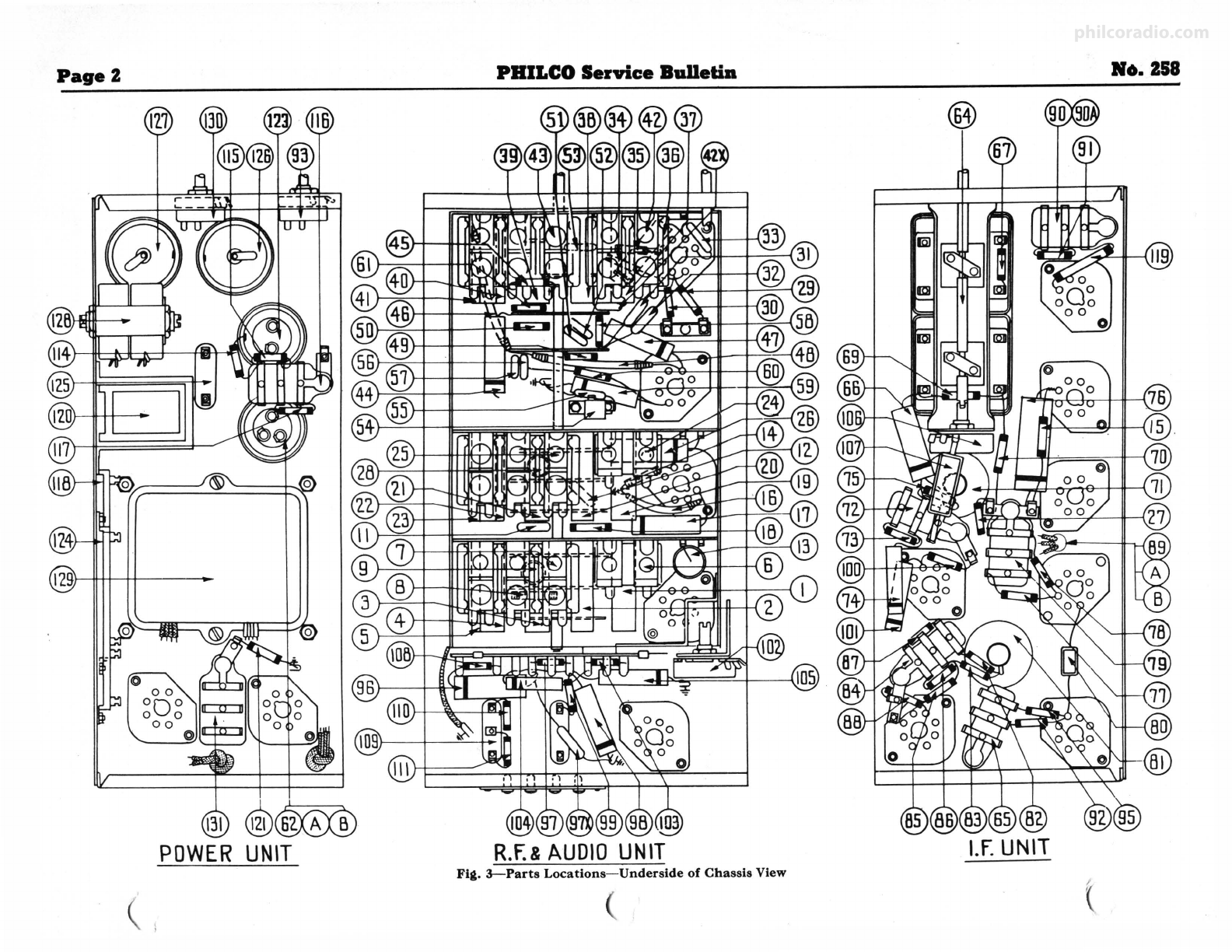
Replacement Parts-Model 37-116
Sch em. Part
No. Descdptlon No.
l Antenna Transformer (Range 1) . . . . . •. . . . . . . . . . . 32-2108
2 Antenna Translormer (Range 2) .......... ... .... 32-2146
3 Antenna Transformer (Range 3) .....•........... 32-2183
4 Antenna Translormer (Range 4) . ................ 32-2185
i ~~::::~"Ii~~'1°br::~~
.<.~~~~
~!:::::::::::::::::it~m
7 Compensator (6 Sections) ...........•....•. .. ... 31-6112
8 Resistor (51000 ollms ½ watt) ....... •. ... • ...... 33-351339
9 Condenser (.05 mtd . Tubular) . . . . . •.•. . . . . •. . . . . . 3o-4020
10 Tuning Condenser ................ • ... . •.. •.... . 31-1892
11 Condenser (40 mmld.) ................. . ..... . .. 30-1076
U gg~3::::~ l5
of::!ft\·iitiu1ai-i:: .-.-...-.::::::::::::: i&-lm
14 Resistor (1. megohm, ½ watt) ........ ...•.. • .... 33-510339
15 Resistor (1000 ohms, ½ watt) ........ . .•. . •. .... 33-210339
16 Resistor (400 ollms wlrewound) ... ............... 33-3016
17 Condenser (.05 mid . Tubular) . . . . . . . . . . . . . . . . . . . 30-4444
18 Resistor (10000 .,hms, ½ watt) ..... .... . . .. . .... 33-310339
19 R. F. Translormer (Range 1) ..... . ... .. ......... 32-2105
20 R. F. Transformer (Range 2) ..........•......... 32-2147
11 R. F. Transformer (Range 3) ........ •. ...•...... 32-2177
22 R. F. Transformer (Range 4) ......•.... •. . •..... 32-2178
23 R. F. Transformer (Range 5) ........ .. . . . . ... . .. 32-2176
24 R. F. Compensator (2 Section) ... .......•. • • ..... 31-6093
25 R. F. Compensator (6 Section) .......... .. . ...... 31-6113
26 Condenser (.05 mid . Tubular) . .... ... .. .• . . .. ... . 30-4123
~~
~:~~~';..l!fo~.::~.T."t.i'tu'l'.!'r\t>:::...·.:::::::::::::it:~&½g
39
29 Resistor (99000 ohms, ½ watt) . . . . • . . . . • . . • . . . . . 33-399339
it
~:~~~~~gg
~i::'1':!.~;:;:tt>_ ·.: : : : : : : : : : : : : : : : : gg:fm
39
32 Condenser (250 mmld. Mica) ...........•.. . ..... 30-1032
33 Resistor (700 ohms Wlrewound) ... .. ••.. . ..•..... 33-170339
34 Resistor (20 ohms, ½ watt) . . . . . . . . . . • . . . . . . . . . . 33--020339
ii ~:~~~:;t8r'::i°id~:rgt\~;.j :.-.-.-...·.:::: : :: :: :::: i~m39
37 Osclllator Transformer (Range I) .... . •. .. ..•..... 32-2191
38 Osclllator Translormer (Range 2) .....•..•. . •.... . 32-2194
39 Osclllator Translormer (Range 3) . ... .. •. ..... .... 32-2197
40 Osclllator Transformer (Range 4) .......•. .• . .... . 32-2198
41 Osclllator Transformer (Range 5) ..... .. ••........ 32-2190
:~xgggir.i::.~~t(i~s~::,~~~ .<.4 Bectlo_n_).': : : : : : : : : : : : : : ~-mi
:~ gg::ir..:.~%?'~~~a~~Jt1~ftlo~):::: : : : : : : : : : : : gAjm
45 Resistor (8000 ollms, ½ watt) . . . . . . . . . . . . . . . . . . . 33-280339
46 Resistor (200 ohms Wlrewound) .. ... . , . .. , . . ..... 7217
:~ ~~~:~~~600~h~~,J;~~~':[Jd): ·.: : ::: : : : : : : : : : : : g~m
:: ~=~ig~ggggggg:::::
~
::m::::::::::::::::::gtg~&m
U gg~3::::~ l~ ::::::itt{l~:l::::::::::::::::::::18:rn:~
g:ggfldc~.r tr2g,)m~ld ..~'.~~) ::: : : : : : : : : : : : : : : : : : l!t½m
gi gg~3::::~ rni
0m~'¥J\,.i1'1i,\:i1:: :::::::: : ::::::::: i:i:rn:i
57 Condenser (25 mmld. Mica) .. .. . . . . . . . . . . . . . . . .. 30- 7
g: ~:~~~:tl°J>Jl.::~.T."tlu'l'!W!::.-...-.::::::::::::: ga- 9
:r~=~igrngggggg:::::
~
:::ii::::::::::::::::::i3 t
61 Electrolytic Condenser (2, 3, 8 mid.) . . . . . . . . . . . . . . 30
63 Condenser (.05 mid . Tubular-Code 121 only) ..... 3
t
~~g~~~!r
~~tt~rii.'ila1<eiitei::::::::::::::::::::~~si1lfJ
66 Condenser (.05 mid. Tubular) . . . . . . . . . . . . . . . . . . . . 30-4123
67 Resistor (1000 ohms, ½ watt) ... . ... . ....... . ... 33-210339
68 Slladowmeter ................... • ... .... •.. .... 45-2189
69 Resistor (1000 ohms, ½ watt) ............. . ..... 33-210339
70 Resistor (1000 ohms, ½ watt) .... ... .... . ..... .. 33-210339
71 Third I. F. Transformer . .. ... ........ .. ... . ... .. 32-2215
72 Condenser (110 mmld. Dual Bakellte) . . . . . . . . . . . . 8035DG
~: ~~~~~e\.5l'llli 0
4°.::ras·T~b~f~:?: .........::::::::::::: itm~
39
75 Resistor (160,000 ohms, ½ watt) .......... . .... . . 33-416339
76 Condenser (.25 mid. Tubular) .......... ... . . . .... 30-4134
~~
I:~ig~lfcl80°~r:-..½½w;!Vti : : : : : : : : : : : : : : : : : : : gt½fclU8
79 Condenser (.05 mid. Dual Bakellte) .......•. . .. . . 3615DG
80 Condenser (110 mmld. Mica) ..... .. ...... .... ... 30-1031
81 Magnet Tuning Transformer . . . . . . . . . . . . . . . . . . . . 32-2217
82 Resistor (490,000 ohms, ½ watt) ... ........•. .... 33-449339
83 Resistor (490,000 ohms. ½ watt) ... ........ . ..... 33-449339
84 Condenser (110 mmld. Dual Bakellte) . . . . . • . . . . . . 8035DG
85 Resistor (490,000 ohms. ½ watt) ...... . . . . . •.. . . . 33-449339
86 Resistor (I meg. ohm, ½ watt) ... . .. ............ 33-510339
87 Resistor (I meg. ohm, ½ watt) .................. 33-510339
88 Resistor (490,000 ohms, ½ watt) . . . . . . . . . . . . . . . . . 33-449339
89 Condenser (Three section .1, .1, .8 mid .) ... ... .... 30-4466
90 Condenser (.01 mid. Dual Bakelite) .............. 3903DG
91 Resistor (20,000 ohms, ½ watt) . . . . . . . . . . . . . . . . . . 33-320339
92 Resistor (1.0 meg., ½ watt) .............. .. . . ... 33-510339
93 Switch (Mag. Tuning) .............. , . ... •...... 42-1216
94 Flood Lamp (Code 122) ............ . ..•..... .. .. 34-2039
95 Resistor (490.000 ohms. ½ watt) .. . . • •... . •• ..... 33
96 Condenser (.05 mid. Tubular) . . . .. . . •. . . . . . . . . . . . 30
97 Resistor (51,000 ohms, ½ watt) ..... . . .. •. . • . .... 33-
97X Condenser (110 mmld. Mica) ........ • ..•. . ... .. . 30-1 I
98 Condenser (.05 mid. Tubular) .... . ....•..•....... 30-4123
99 Resistor (99.000 ohms, ½ watt) . .. . . . • . . . . . . . . . . . 33-399339
rnr
~~~!~e~
l"o1gmll;i,;t~tiari:........::::::::::... itmi39
102 Volume Control. .................... .. .•..•.... 33-5158
103 Resistor (70,000 ohms, ½ watt) .................. 33-370339
104 Condenser (.008 mid. Tubular) ...... . .......•.... 30-4112
105 Condenser (.006 mid. Tubular) ........ . .• . . .. , ... 30-4445
106 Potentiometer (Expander unit). . . . . . . . . . • . . . . 33-5172
107 Condenser (100 mmld. Mic a) ..........•. • .. • .... 30-1035
108 Resistor (240,000 ohms, ½ watt) ... . .. . . ......... 33-424339
109 Input Audio Translormer ............•. . •..•. . .. 32-7057
110 Resistor (25,000 ohms, ½ watt) ...... . . .. . . .. . . .. 33-325339
111 Resistor (25,000 ohms, ½ watt) . . . . . . . . . . • . . • . . . . 33-325339
112 Output Transformer... .... ..... 32-7717
113 Cone and Voice Coll .... .. .......... .. ... . . . . .. . 36-3647
114 Resistor (330,000 ohms, ½ watt) . . . . . . . . . . . • . . . . . 33-433339
m~:~!~J/~
0i~i 11
~ ..11a1:ltl.i ·:: ·:::::::::::: 1gsti~~
0
117 Resistor (51,000 ohms, ½ watt)..... . . .•....... 33-351339
118 Resistor (14,000 ohms, ½ watt). .. .. . . . 33-3291
Flp• In blaek type Indicate circled llguree In Bue View.
Ll1t
Price
so.so
.80
.60
.70
.80
.40
1.40
.20
.20
3.75
.·.26
.20
.20
.20
.20
.20
.75
.60
.60
.60
.70
.40
1.40
.20
.20
.20
.20
.20
.25
.25
.20
.20
.20
.·.so
.80
.50
.50
.50
1.00
·t'.26
.20
.20
.20
.20
.25
.20
.20
.25
.25
.25
.25
.25
.20
.20
.20
.25
.20
.20
1.60
.·.35
.20
.20
.·.26
.20
.·.25
.20
.25
.20
.25
.20
.20
.40
.20
.·.26
.20
.25
.20
.20
.20
.20
1.40
.30
.20
.20
.75
··.20
.20
.20
·.20
.20
.20
.25
1.00
.20
.20
.20
·.20
3.50
.20
.20
2.00
2.25
.20
.20
.40
.20
Schem. Part
No. Deecrlptlon No.
119 Resistor (20000 ohms, I watt) . . . . . . . . . . • . . • . . . . . 33-320439
120 Clloke (Filter) .. .... ......... .... ........ , ..... 32-7491
m~':1~tg~1\
1
M~lfi':ea~e~~~~>...·.·.:·.·.·.·.:·.:·.:·.·.·.:·.·.·.:~~t39
123 Electrolytic Condenser (8 and 10 mid.) .....•..... 30-2123
124 Resistor (1000 and 4000 ohms) ........ -. . . . . . • . • . • 33-3289
125 Choke (Filter). . . . . .. .. .. . . . . . . . . . . . . .. . . . . . . .. 3i-7056
126 Electrolytic Condenser (8 mid.) . .. . . . . • . . . . . . . • . . 30-2026
127 Electrolytic Condenser (8 mid.). . . . . . . . . . . . . . . . . . 30-2026
128 Potentiometer (Dual 60 ohms) . . . . . . . . . . . . . . . . . . . 33-5176
129 Power Transformer 115 Volts, 60 Cycle ........... 32-7688
Power Transformer 115 Volts, 25 to 40 Cycle ...... 32-7689
Power Transformer, 220 Volts .......... . ... . . ... 32-7690
130 Power and Tone Switch.. .. .. . . . . . . .. . . . . . . . . . . . 42-1196
131 Condenser (.015 mid. Dual Bakellte) ..... ..... ... 4989DG
132 Range Switch (Osc) ............................ 42-1217
133 Range Switch (R. F .) .......... . ........ . . . ..... 42-1212
134 Range Bwltcll (Ant.) ...... . ..................... 42-1211
135 PIiot Lamp (Codes 121-122) ...... ...... .. . ...... 34-2039
136 Bhadowmeter Lamp (Code 121 only) .............. 34-2039
USED ON CODES 121-122
Dial Screen Holder Assembly .... ,................ 31-1900
Coup!lng Assembly (Tuning Condenser) . .......... 31-1907
Screw ............. .. .... . . ...... ....... ..... .. W-650
Set Screw . . . . . . . . . . . . . . . . . . . . . . . . . . . . . . . . • . . . . W-644
~~!~:;,~D6~ri~r~t~Jait'.'.'.'.'.' ...::: : : : : : : : : : : : : : : : : :
~~A~Y
Retaining Clip. . . . . . . . . . . . . . . . . . . . . . . . . . • . . . . . . 28-4394
~g~1ig,ie'
iiiiiex.i>iat,, i:ii.,iilieswtictii·.:::'.:·.:·.::·.·.:tml
Socket (8 Prong) ...................... .. . . •.... 27-6058
Socket (7 Prong) ........ . .. ....... .... ...... ... 27-6057
Socket (Power Transformer) ...... ... ....•..••. .. 27-6061
Tube Sllleld. . . . . . . . . . . . . . . . . . . . . . . . . . . . . . • . . . . 28-2726
Tube Shield Base.. .. . .. . . . . . . . . • . . . . . . . . . . . . . . . 28-3898
Tube Bllleld (6N7G) ...... . ..... , . . . . . . . •. . . . . . . 8005
Tube Shield Base (6N7G).. . . . . . . • . .. . • . . . . • . . . . 8004
Mtg. Grommet (R. F. U.nlt) ......... . ... • ..•.... 27-4317
Mtg. Sleeve (R. F. Unit) .. .... . . ...... . .... . . ... 28-2257
Mtg. Screw (R. F . Unit) ..... . ........•..•...... W-729
Mtg. Spacer (R . F . Unit) Code 121 ........•...... 27-8339
~m:~:,:'fe/R : .~·.~~It!
-~~~
.'.2.2·:: .':::::: '.::::
~~J~~
Mtg . Rubber Tuning Condenser .................. 27-4325
m~:iY!t~gci~ 0.;:::~t~rni.;,i::.-.::::::::::::::lii~5~
Mtg, Spacer (R . F. Transformer) ... .. ••...... ... . 27-8228
Mtg , Screw (R. F . Transformer) ........ • . • . . .... W-1635
Terminal Panel Antenna ................... • ... . 38-7714
Terminal Cover (Speaker). . . . . . . . . . . . . . . • . . . . . . . 36-3672
Knob .. . ........................ • ........ .... . 27-4330
Knob. . . . . . . . . . . . . . . . . . . . . . . . . . . . • . . • . . . . • . . . . 27-4331
Knob ......................................... 27-4332
Knob ....... ..... ................ .... ......... 27-4326
Cable (Speaker) . . . . . . . . . . . . . • . . • . . . . . . . . . . . . . . . 41-3220
A. C. Plug and Cord ................ ... . ... . .... L-2288
Fuses.. .. .. . . . .. .. .. . . .. . . . .. • • . . .. . . .. • . . . . . . 45-2046
Cllassls Mtg. Rubber .........• .•.•• .. ..... •. ... 3558
Rubber Bushing (Small) . . . . . . . . . . . . • . . . . • . • . . . . 27-4359
Rubber Bushing (Large) .... . .. . . • .• •. •.. •...... 27-4360
~==::r.ir:::::::.·.·...·.·.·.·...........·.·.·.·.·.·...·.·.·.·.·.·.·.·.·.itm:
Aconstlc Clarlfter (Type K) . ....... .•..•. ...•.... 36-1155
Bottom Bllleld. . . . . . . . . . . . . . . . . . • . •. . • . . . . • . . . . 38-8142
Snap Fasteners. . . . . . . . . . . . . . . . . . . . . . . . . . . . . . . . . 28-4279
PIiot Lamp Assembly ............ ; ............ .. 38-7909
CODE 121
Dial. ... .....•..... ... .................... . ...
Hub .. ..........•..•. •.. .• . .......... ... •. . . ..
Clamp ............. . . .•....... . ....•....•... ..
Set Screw .................................... .
Gear (Dial) .......... ... ........ .. ............ .
Gear Drive ..... ............•.•..•....•..•.....
Thrust Spring ........ . ....... . . . .............. .
Thrust Washer ............. .. ... . • ..•.... ... ...
C Washer ....................... . ............ .
M~ .... . .. ......... ........ ..... ..... . ..... .
Mask Arm and Link A88embly .......... . .. . .... .
Mask Washer ........ . ................ . . ...... .
Mask Gulde and Bracket ....... .. ........... ... .
Drive Mounting Assembly .. .................... .
Vernier Drive .......................... .. ..... .
Bezel Frame and Plate A88embly (Cabinet) ....... .
Glass .............. ·,·,············· · ·· ······ ·
~~ei:::·.·.·.::::::::::::::::::::::::::::::::::
CODE 122
27-5249
28-7187
28-2837
W-1641
28-7185
31-1884
28-8611
28-3976
28-3904
27-6206
31-1899
27-8318
38-7876
31-1901
31-1895
40-5948
27-8300
28-3988
27-8313
Auto Dial Tuning Assembly Complete ......... . .. 31-1886
Dial Scale.. .. . . . . . . . .. . .. .. . . . . .. . .. . . . . . . . .. . 27-5207
Gasket (Dial Beale) . ....... ......... . ...... ..... 27-8398
Mask and Link Assembly .. . . ..... ... . .. ........ 45-2328
Mask Gulde .. .. . . . ...... ... ............ .. ..... 28-411R
Ring (Retaining Mask Assembly) ...... . •.•...... 28-7195
Spring (Retaining Mask Assembly) . . . . . . . . . . . . . . . 28-8629
Indexln nger ..........................•.... 31-1898
Plunger and Switch Assembly. . . . . . • . . . . . . . . 45-2330
Ran Shalt Coupllng ........ .. ... . . . .... 2R-7198
Felt ................ ...... ... . . .. . . . ... 27-8399
Washer ... . ............... .. ........ . .... ..... W-495
Snap Fastener.. . .. . . .. .. . . . .. . . . . .. . . • .. . . . . .. 28-4279
Indexing Handle. . . . . • . . . . • . . . . • . . • . . . . . . . . . . . . 45-2329
Handle Cover . . . . . . . . . . . . . . . . . . . . . • . . • . . . . • . . . . 28-4077
Set Screws . . . . . . . . . . . . . . . . . . . . . . . . • . . • . . •. . . . . . 28-6493
Screws (Cover) ........................ .. ....... W-1669
Dial Escutcheon Aasembly. . . . . . . . . . . . . . . . . . . . . . 45-2324
Flood Lamp Aasembly ......................... . 38-7937
Bezel Frame and Plate Assembly (Cabinet) . . . . . . . . 40-5980
Bezel Gasket. . . . . . . . . . . . . . . . . . . . . . . . . . . . . . . . . . 27-8517
Screw. . . . . . . . . . . . . . . . . . . . . . . . . . . . . . . . . . . . . . . . . W-480
Station Tab Kit ....... . ........................ 40-6013
Prices Subject to Chanae without Notice.
Llat
Price
$0.20
.95
.20
·1·.00
.50
2.20
1.05
1.05
·foo
.·.ts
.40
2.00
1.60
1.60
.15
.15
.30
··.or.
Per C·..a
.50
.11
.11
.·.io
.03
.10
.03
.04
.01
Per C .45
Per C .40
··.oi
Per C·.10
.02
.01
Per C .30
.15
.15
.10
.10
.10
.10
.50
.·..a
.40
.12
.10
.02
.10
··.oi
PerC.30.01
.30
.50
Per C .50
.25
.·.so
.06
.45
.01
philcoradio.com

No. 258 PHILCOService Balletill Pages
13
~
'"
{I).AttT.·RANGl 1 Q)ANl. -RANGl?. @ANT : RANGE3 @ANT .-RANGE4 @ANT .-RANU 5
QYR.FRANGE1 @)R.f. -RANl'.f.2 @R.F. -RANGE3 @RS. -RANGE4 @)RS. - RANG[ 5
@osc.-RANG[ I @ osr.·RANG[2 @osc,RANG[ 3 @osc ,RANU
~
@.osc .-RANG( 5
Fla. 5-Coll Wlrlna
~
l.F EXPANDERUNIT "'
g
i~
@)MA GTUN.TRANS.
The numbers on the coil leads correspond to those shown on the schematic diagram. For example: On Antenna transformer (I) lead No. I is connected
to range switch wafer contact A6.
HUM ADJUSTMENT
With Volume control at minimum volume position,
adjust Potentiometer (128) on power unit for minimum
hum.
SHADOWMETER ADJUSTMENT
Code 0l2l
Remove aerial and allow tubes to warm up. Then
adjust shadow meter as follows:
I. Move the shadow meter coil backwards and for-
wards, until the opposite edges of the shadow are ¾ of
an inch from each end of the shadow screen, measuring
along the bottom edge of the screen. Adjustment of
the shadow meter light bracket may be neceBSary for
perfect centering.
2. Remove the rectifier tube from its socket, and
rotate coil until shadow reaches minimum width . This
width must not exceed 1
,{, of an inch.
3. Replace the 5U4G rectifier tube in its socket. The
shadow should then widen to not more than 1
,{, inch or
less than 1
,1',inch from each side of the screen measuring
along the bottom edge. If these limits are not attained
readjust the shadow meter as given in paragraphs I
and 2 until they are reached .
DISCRIMINATOR
@
3Ro.l.F.
TRANS.
~ .F.EXPANDERUNIT
MJkTUN.
AMP.
6K7G
1sr.l.f.
6K1G
Fla. 7-Locatlons of I.F. Compensators
Top of I.F. Unit
ANT.-5.0M.C. 1A
ANT.·1.0M.C.
ANT~l'lM.C.
@
@
BLACK
vrn1rt
BLACK
BLACK- -~HITE-TR.
'ftllOW
Fla. 6-Speaker Wlrlntt
J-ii---:[email protected].
Ltf:=:::'.::::'.___ ~24 R.F.-4.5M.C.
----'--1 6 ANT.-1400 K.C.
'------'--i@ ANT.-4.5 M.C.
Fltt. 8-Locatlons of R.F. Compenaators
Underside of ChaBBls View
philcoradio.com

Page ·& PHILCO Service Bulletin No. 258
Alignment of the Compensalors
To accurately adjust this receiver, precision test equipment is nece99ary.
A signal generator such as the PHILCO MODEL 088 SIGNAL GEN-
ERA TOR , covering from 110 to 20,000 K. C. is recommended for adjusting
the compensators at the vllrious frequencies specified. A visual indication
of the receiver output is also nece99ary to obtain correct adjustment of the
compensators. PHILCO MODEL 025 CIRCUIT TESTER contains a
sensitive out1>11tmeter and is recommended for these adjustments.
Philco Fibre Handle Screw-driver No. 27-7059 completes the necessary
equipment for these adjustments. The locations of the various compensa-
tors are shown in Figs. 7 and 8.
NOTE-The receiver should be allowed to heat for at least 15 minutes
before adjusting the compensators.
OUTPUT METER
The 025 Output Meter is connected to the plate and cathode terminals
of the 6F6G tube . Adjust the meter to use the (0-30) Volt Scale.
DIAL CALIBRATION
In order to adjust this receiver correctly the dial must be aligned to track
properly with the tuning condenser . To do this proceed as follows:
I. Loosen the set screws on the shaft coupling of the tuning condenser.
Then turn the tuning condenser until the plates are in the maximum
capacity position. Now set the glowing beam indicator on the index line at
the low freque'1CY end of the broadcast band . With dial and tuning con-
denser in this position tighten set screws.
l. Turn the tuning condenser control until the indicator is on the first
division from the index line.
3. With the dial in this position, loosen the shaft coupling set screws .
Then turn the dial until the indicator is again on the Index line . Tighten
the set screws in this position.
NOTE: Be careful when turning the dial that the position of the tuning
condenser is not disturbed.
INTERMEDIATE FREQUENCY CIRCUIT
Frequency 470 K. C.
I. Connect the 088 Signal Generator output lead in series with a .I mfd.
condenser to the grid of the 6L7G tube, and the ground connection of the
output lead to the chassis.
2. Set the receiver volume control in the maximum position. Turn the
fidelity-selectivity control clockwise; magnetic tuning control in the "off"
position (counter-clockwise); range switch in position No. 1 (Broadcast);
tuning condenser to approximately 580 K. C., and adjust the signal gen•
erator for 470 K. C.
3. Now adjust compensators (64B) 1st I.F. Sec., (64A) 1st I.F. Pri.,
(64D) 2nd I.F. Sec., (64C) 2nd I.F. Pri., (71S) 3rd I.F . Sec., and (71P)
3rd I.F . Pri. for maximum output.
4. Turn the fidelity-selectivity control to the expanded position (counter·
clockwise). The intermediate frequency curve is now checked for symmetry
as follows: Slowly shift the signal generator dial between 460 K. C. and
480 K. C. As the dial is turned two peaks will be indicated on the output
meter-one about 46S. K. C., and the other about 475 K. C. These peaks
should &ivethe same deflection or reading on the output meter . If they are
unequal, compensator (71S) must be readjusted slightly to the right or left-
<!epending on which peak gives the lowest reading-until they are equalized.
Each time the compensator is set in another position, rotate the signal
generator dial .through 460 to 480 K. C. and note the reading of each peak
on the output meter. If the peaks become more equal when compensator
(71S) Is turned to the left, continue in this direction until they are equal.
If they become more unequal turn the compensator to the right. Continue
this adjustment In either direction until the peaks equalize.
5. After adjusting the third I.F . transformer, turn the fidelity -selectivity
control clockwise (selective position) and adjust the attenuator of the
signal generator for maximum output. Now tune the primary compensa-
tor (SIP) of the magnetic tuning transformer for minimum output.
RADIO FREQUENCY CIRCUIT
Tunlna Ranae U.5-18.2 M. C.
I. The signal generatcr output lead with the .1 mfd. condenser, is con-
nected to terminal No. 1 on the aerial input panel (rear of cha88is) and the
generator ground lead to terminal No. 3. Terminals 2 and 3 must be con-
nected with the shorting link provided on the panel.
2. Set the magnetic tuning control in the "off" position, and the fidelity-
selectivity control In the extreme clockwise position. Set the range switch
in position No. 5 (11.5 to 18.2 M. C.) Turn the receiver and signal gen·
erator dials to 18 M. C. and adjust the generator attenuator for a readable
Indication on the output meter. Now adjust compensator (43D) by turn•
ing t~e screw (clockwise) to the maximum capacity position, then slowly
turn 1t counter -clockwise until a second maximum peak is reached on the
output meter. The first peak from maximum capacity is the image signal
and the receiver must not be adjusted to this signal. On some receivers,
however, only one peak will be found, therefore, adjust compensator (43D)
to this peak. If the above procedure is correctly performed, the image
aignalwill be found at 17.060 M . C. by advancing the signal generator input,
and turning the receiver dial to this frequency mark on the scale .
3. Leaving the aignal generator and receiver dials at 18 M. C, the
antenna and R. F. compensators (7D) and (25D) are now adjusted by
connecting a variable condenser (Philco Part No. 45-2325) across the
oscillator compensator (43D) contact (first contact from the left side of
the receiver facing rear underside view of the chassis) and ground. Now
tune the added condenser until the second harmonic of the receiver oscillator
beats against the algnal from the generator, resulting In a maximum indica-
tion on the output meter. Note: It may be necessary to increase the signal
generator output to obtain a aignalof sufficient strength for reading on the
output meter. Compensaton (7D) and (25D) are now adjusted for maxi-
mum output. After these adjustments, remove the external condenser and
readjust compensator (43D) as given In paragraph 2 above .
4. Turn the algnal generator and receiver dials to 12 M. C. and adjust
compensators (43E), (25E) and (7E) for maximum output.
5. Readjust compensator (43D) as given In paragraph 2 above, for
maximum output .
6. Readjust compensators (7D), (25D) and (43D) as given In paragraph
3 above. This readjustment Is to correct any variation that the low
frequency compensator may have caused in the high end of this range.
Tuning Range (7.35-11.6 M. C.)
I. Turn selector switch to Range 4. Set the aignal generator and receiver
dials to 11.0 M. C. Now adjust compensator (43B) for maximum output.
Check for image at 10.06 M. C.
2. Leaving signal generator and receiver dial turned to 11.0 M. C., con-
nect the external variable condenser across the oscillator compensator
(43B) contact (third contact from left aide of the receiver facing rear
underside view of cha88is) and ground. Tune the added condenser for
maximum output, then adjust compensators (7B) and (25B) for maximum
output . Remove the added condenser and adjust (43B) for maximum.
3. Turn the signal generator and receiver dials to 7.5 M . C. and adjust
compensator• (43C), (25C) and (7C) for maximum output.
4. Readjust compenaator (43B) as given In paragraph 1 above.
5. Readjust compensator& (7B), (25B) and (43B) as given in paragraph
2 above.
Tuning Ranae (4.7 to 7.4 M. C.)
I. Turn selector ewitch to range 3. Set the signal generator and receiver
dials for 7.0 M. C. aild adjust compensators (43), (25) and (7) for maximum
output.
2. Rotate the signal a:eneratoreand receiver dials to 5.0. M. C., then
adjust compenaators (43A), (25A) and (7A) for maximum output.
3. Readjust compensators (43), (25) and (7) on the 7.0 M. C. signal.
Tuning Ranae (1.58 to 4.75 M. C.)
I. Turn the selector switch to range 2. Set the signal generator and
receiver dials .fo 4.5 M. C. Now adjust compensators (42B), (24A) and
(6A) for maximum output.
2. Rotate the aignal generator and receiver dials to 1.7 M . C. Com-
pensator (42C) Osc. series is now adjusted for maximum output as follow•:
First tune compensator (42C) for maximum output, then vary the.
tuning condenser of the receiver for maximum output about the 1.7 M.C .
dial mark . Now turn compensator (42C) alightly to the .right or left and
vary the receiver tuning condenaer for maximum output. If the output
reading increases, turn compensator (42C) in the aame direction a trifle
more, and again vary the tuning condenser for maximum output . If the
output decreases, set the compensator In the oppoeite direction . This
procedure of first setting the compensator and then varying the tuning
condenser is continued until there is no further a:ain In output reading .
3. Readjust compensators (42B), (24A) and (6A) for maximum output
as given in paragraph 1 above.
Tuning Ranae (530 to 1600 K. C.)
I. Set selector switch in range 1. Rotate the eignal generator and
receiver dial to 1500 K. C. Adjust compensators (42)'. (24) and (6) for
maximum output .
2. Turn the signal generator and receiver dials to 580 ·K. C. Compen-
sator (42A) Osc. series Is now adjusted, using the same procedure as given
in paragraph 2 under Tuning Rana:e (1.58 to 4.75 M. C.). The only dif-
ference in the two adjustments is the frequency and compensator used .
3. Readjust compensator (42) on 1500 K. C. and compensatora (24) and
(6) on a 1400 K. C. signal .
ADJUSTMENT OF THE MAGNETIC TUNING CONTROL
I. Leave the selector switch in position 1. Set tlle fidelity-selectivity
control in the "selective" poeition (clockwise). Magnetic tuning in the
"out" position. Turn the signal generator and dial to 1000 K: C., then
adjust the receiver tuning condenser for maximum output.
NOTE : It is very important to accurately adjust the receiver tuning
condenser. also, adjust the signal generator attenuator to maximum output .
2. Turn the (Magnetic Tuning Control) to the "on" position (clock-
wlae). Compensator (81S) Sec. of magnetic tuning transformer is now
adjusted for maximum output . If the indicator of the output meter goes
off scale, turn the volume control of the receiver toward the minimum
poeition until a readable indication is obtained.
3. The above adjustment is now checked for accuracy, by turnina: the
magnetic tuning control "off". When this is done there should be no
change in the tone of the receiver signal. If a change:of tone or a hi88develops,
it indicates a shift in frequency and the adjustment must be made again.
philcoradio.com

No. Z58 PHILCO Service Bulletin Page7
New Profit-Makers and Time-Saversfor R.M. S.
Now... PHILCObringsyou the New
IDENTIFIED RESISTORS
Put
No,
45-1146
in all popular values !
The Grtatest Th1ite S.vtr and Convenience recently
de.,.loped for S.rvicemenl Th111 resl,ton hn lnt their
value ste,nped on • lit att«hed In one IHd, 1llm ln1t1
bother about color code , and doubt about their nlue . They
will sa.-e YOU ti••and houble In 111your service worlr.
Get this convenient lcit of selected values
uted in the most common ,enice jobs, end HI
For yountlf how they will help yo11I Once
you UH them .,ou will ncvcr u,e any other , . . .
end they ere priced 11 low 11 ordinary old
1tyl1 reslstonl
Hancly Serviceman's Kit
3ll Resistors, A11ortecl Values
LIST PRICE $6.40
Get this handy
TUBE SOCKET
and
EYELET ASSORTMENT
An auortment of quality tube sockets is an essen-
tial for any servicemen or de1ler '1 terv ice
department-and a neceuity for the experi-
menter or Ht-builder . Thi, kit contain, 1i1 each
of all types of 1ockeh from four to seven-prong
typH , to9ether w;th 100 eyelets for mount;n9 .
A representative ,tock
♦
hat
i
♦
will pay you
• lwey1 to have h•ndy . Port No, 45-1225. •
.
Handy PILOT
SERVICES MOST
ANY RADIO!
LAMP KIT NOW!-
A IALANCED
ASSORTMENT OF
SMALL HAIIDWAIIE
1110d 111all
SERVICE WOIIKI
PHILCO EYELETAND
DRIVE SCREWKIT
·,robably more pilot lamp, •re
replaced in radio Hh than any
other part - every Hrviceman
sho":ld have • portable 111ort-
ment of the11 to carry with him
on all service ca lls. Here i1 one
especia lly prepared for you at
minimwm price and in con'llenient
form. Order several of the•• and
be ready for any emerqel'lcy .
40 LAMPS ...
10 of Hell popul., type
DISPLAY THIS BOX
ON YOUR COUNTER PART No. • ···. 1
45-1226
A Hlected taorbaent ol .-11 .
h
■
rdw
.. INlls 11enentlel lo
quick eHlclent shop HrYiclaa
11 weh u experl•ental -'c.
Here Is t co•plett
b
■
ltncod
nltctlon cofflplled by ••
11loyet1
ofIhaPhilco
N
■
tloul
Strvlc
■
St
■
llon
titer
Y
■
-1
of
experlnce In h1ncllln1
■
II
kinds of service Job,. Every
type of 11ut,bolt, rivet,
■
nd
drive scraw
ordln
■
rlly
und Is
Included.
Get 1h11ldt
■
1
■
n
lnvest•enl
In ti••
■
nd
lroublt•Hvlnr-
be
■
deqHltly
prepared for_
your hardwere netd1 for •
lon1 II•• lo co••·
COMPLETE!
COMPACT!
INDISPENSABLE!
LIST
PRICE
s6.1s
SAVES TIME t, MONEY FOIi YOU
PART No.
45-1150
Brand New-BAKELITE CONDENSER Quick, Efficient Service Worf&..
August, 1936
UNIVERSAL
MOUNTING
TYPE
ASSORTMENT SAVES .YOU TIME & MONEY
Easily Installed-
All Heeded Values!
New ! Latest style 1i1-lu9 universal balel ite con •
deniers u used in all current Philco, . A full rang•
of veluH in
♦
his
popular serv ice pert , conveniently
mounted , each one ple inly ma rked with J:>arlnumber
end velue.
Eesily in,ta lled and connected-su itable for many
service app licet ions . Every serviceman should keep
et least one of these condenser
CONTAINS
ALL TOOLS
lll(j)UIIIED
IN ALL
OIIDINAIIY
SERVICE
OPERATIONS
PHILCO RADIO & TELEVISION CORPORATION
Parts and Service Division
DESIGNED
IY PHILCO
TO MIET THI
NEIDS OF
EVERY
UP-TO-DATE
SIIIVICEMAN
Part No.
45-1230
Printed in U. S. A.
philcoradio.com
Table of contents
Other Philco Radio manuals

Philco
Philco 121 User manual

Philco
Philco CSP790BC User manual

Philco
Philco 37-640 User manual

Philco
Philco 121 User manual

Philco
Philco 623 User manual

Philco
Philco 611 User manual

Philco
Philco 121 User manual

Philco
Philco PHOTOFACT 49-1150 User manual

Philco
Philco 37-670 User manual

Philco
Philco 37-630 User manual