Philco 37-675 User manual

·-s
• • • • • • • • • • • • • • 'YflJJdlll 37-675
FOR MEMBERSOF
RADIOMANUFACTURERSSERVICE SERVICEBULLETIN
No. 261
Model 37-675-Codes IZl-lZZ
Electrical Specifications
Type of Circuit: Superheterodyne with Magnetic Tuning; Spread-
band dial; Philco Foreign Tuning System, and a class "A" Audio
Output Circuit . Code 122 receiver has the Philco Automatic Dial
tuning system.
Power Supply: 115 Volts A.C. 50 to 60 cycles or 25 to 40 cycle.
Power transformer Part Numbers for the different voltage and
frequency ranges are listed on Page 5.
Power Consumption: 155 Watts.
Intermediate Frequency: 470 K.C .
Undistorted Output: 10 Watts.
Philco Tubes Used: Twelve (12)-3 -6 K7G; 3-6F6G; 1-6 L7G;
1-6N7G; 1-6A8G; 1-6Q7G; 1-6 H6G; 1-5X4G.
Tuning Ranges: Five - Range 1- 530 to 1600 K.C.; Range 2- 1.58
to 4.75 M.C.; Range 3-4.7 to 7.4 M.C.; Range 4-7 .35 to 11.6
M.C.; Range 5-11.5 to 18.2 M.C.
Tone Control: Twin Tone Controls-
A. Continuously variable treble control
B. Three point variable bass compensation
Speaker: U~15. Aerial Connections
To obtain the full advantage of the sensitivity of this receiver the
Philco High Efficiency Aerial supplied with the receiver must be used.
The connections for the aerial are as follows:
The red and black leads of the High-Effi ciency Aerial "transmis-
sion line" are connected to terminals 1 and 2 respectively, of the
terminal panel provided on the rear of the chassis . Connect the
jumper on the terminal panel across terminals 3 and 4.
If a:temporary aerial is used, the jumper should be across termin als
2 and 3. The aerial connects to terminal 1 and the ground lead to
terminal 3. A good ground connection is desirable in all installations .
DIAL CALIBRATION
In order to adjust this receiver correctly the dial must be aligned
to track properly with the tuning condenser. To do this proceed
as follows:
1. Loosen the set screws on the shaft coupling of the tuning con-
denser. Then turn the tuning condenser until the plates are in the
maximum capacity position. Now set the glowing beam indicator on
the index line at the low frequency end of the broadcast band. With
dial and tuning condenser in this position tighten set screws.
2. Turn the tuning condenser control until the indicator is on the
first division from the index line.
3. With the dial in this position , loosen the shaft coupling set
screws. Then turn the dial unt il the indic ator is aga in on the index
line. Tighten the set screws in this position.
NOTE: Be careful when turning the dial that the position of the
tuning condenser is not disturbed.
REPLACING AUTOMATIC DIAL CONTROL SCREWS
Code 122
See Bulletin 258 for the procedure on removal of the Automatic
Dial Control screws.
REPLACING THE DIAL OR MASK ARM ASSEMBLY
Code 122
To replace the dial or mask arm assembly, remove the chassis
from the cabinet. Then remove the dial tuning knobs. Take off the
control handle cover by removing the three screws holding it to the
handle hub. When the metal cover is removed, two screws will be
noted holding the control handle to the rotary hub . Remove the
screws and detach the handle.
Now remove the five screws holding the dial escutcheon plate to
the dial body and lift the escutcheon from the dial body. With these
parts removed, the dial may be detached.
MASK ASSEMBLY-Code 122
With the dial removed, two fibre rin gs and one metal ring will be
found around the"outer side of the dial housing. Take off these rings
and slip the mask .from the housing.
FRONT OF CHASSIS
00
AIL VOLTAGESMEAS·@
·II/UP FIWMSOCKET
CONTACTSTOliNP. 0
EXC£PTASNOTED. 0
- - - - -
""~
6F6G
OUTPUT
l 4
□
V.
'
I \
63VAf. 63V.AC.
320\J. 0 31.01/.
320V : 00 ; 20V
o G
·33\1. ·33'1.
6K7G
~
-1.s,cm
s
□
v~
200V.
sov IBOV 6K7G
~
6L7G i:.';~,. . •~
MIXER
~
o,,,oo H p O a
-'~~--- 6.3V>C p O a o
I00V O 20SV63V.A..
6K7G ~-,. "6CJ7G
R.F. ~o O 2110-.oer.
IST,AUDIO.AV.C.
6.3V.A~
6F6G ~o
DRIVER 205V QoH
- 20!>. 00
6.3V.A..C
Fill. I-Socket Voltaites, Measured from Underside of Chassis
The voltages indicated by arrows were measured with a Philco 025 Circuit Tester
which contains a voltmeter having a resist ance of 1000 ohms per volt. Volume
Con tr ol at minimum , range switch in broadcast position, line voltage 115 A. C.
SHADOWMETER ADJUSTMENT - Code 121
Remove aerial and allow tubes to warm up. Then adjust shadow
meter as follows:
1. Move the shadow meter coil backwards and forwards , until the
opposite edges of the shadow are ½of an inch from end of the shad-
ow screen, measuring along the buttom edge of the screen. Adjust-
ment of the shadow meter light bracket may be necessary for perfect
centering.
2. Remove the rectifier tube from its socket, and rotate coil until
shadow reaches minimum width . This width must not exceed 3
,12 of
an inch.
3. Replace the 5X4G rect ifier tube in its socket. The shadow
should then widen to not more th an 3
,{6 inch or less than ½'6 inch
from each side of the screen measuring- along the bottom edge. If
these limits are not obtained read just the shadow meter as given in
parag rap hs 1 and 2 until they are reached.
w
:::i
...J
co
@
BLACK
@ YELLOW
\c;R EEN-\/'JH11£.·TR.
Flit . 2-U15 Speaker WlrlnQ
Copyright I936, Philco Radio & Television Corporation
philcoradio.com

Page2 PHILCO Service Bulletin No. 261
Fig. 3- Parts locations. Underside of Chassis
( :, ( (
philcoradio.com

No. 261
-·
.,../
...., '"·' "
'
'
@1sr. 1.F.TRANS.
Page3
philcoradio.com

Page4 PHILCO Service Bulletin No. 261
Alignment of the Compensators
To accurately adjust this receiver, precision test equipment is necessary .
A signal generator such as the PHILCO MODEL 088 SIGNAL GEN-
ERATOR, covering from 110 to 20,000 K. C. is designed for adjusting the
compensat ors at the various frequencies specified . A visual indication of the
receiver output is also necessary to ohtain correct adjustment of the com•
pensators . PHILCO MODEL 025 CIRCUIT TESTER contains a sensitive
output meter and is recommended for these adjustments.
Philco Fibre Handle Screw-driver No. 27-7059 completes the necessary
equipment for these adjustments. The locations of the various compensators
are shown in Figs . 5 and 6.
NOTE-The receiver should te allowed lo heat for at least 15 minutes
before adjusting the compensators.
OUTPUT METER
The 025 Output Meter is connected to the plate and cathode terminals
of the 6F6G driver tube . Adjust the meter lo use the (0-30) Volt Scale.
INTERMEDIATE FREQUENCY CIRCUIT
Frequency 471 K. C.
IMPORTANT- Before adjusting the compensators, calibrate tuning
dial u given on Page I .
I . Connect the 088 ·signal Generator output lead in series with a I mfd.
condenser to the grid of the 6K7G tube, 2nd I.F., and the ground connection
of the outp ut lead to the chassis.
2. Set the receiver volume control in the maximum position; tone control
counter-clockwise; Magnetic Tuning Switch "Off" (counter-clockwise);
range switch in position No. I (Broadcast); bass compensation switch on
first tap from "off" position, and the receiver dial to approximately 580 K . C.
Adjust the signal generator tor 470 K. C.
J. Now adjust compensator (84P) for maximum output.
4. Remove the signal generator output lead with the .I mfd. condenser
from the 6K7G 2nd I.F. grid and connect them to the 6K7G, Isl I.F. grid.
5. Tum compensator (69T) clockwise until it is tight, then adjust com-
pensator., (68) and (69S) for maximum output. Now adjust compensator
(69T) for maximum output. Caution: Do not adjust compensators (68) and
(698) unless compensator (69T) is turned to the extreme clockwise position.
6. Rem ove the signal generator output lead and condenser from the
6K7G, 1st I.F . tube and connect them to the grid of the 6L7G tube, Isl
detttto r, and adjust compensators (64P) and (64S) for maximum output.
RADIO FREQUENCY CIRCUIT
Tunlna Ranae 11.5-18.2 M. C.
1. The signal generator output lead with the .I mfd. condenser, is con-
nected to terminal No. I on the aerial input panel (rear of chassis) and the
generator ground lead to terminal No. 3. Terminals 2 and 3 must be con-
nected with the shorting link provided on the panel.
l. Set the magnetic tuning control in the "off" position . Set the range
IWitch in position No. 5 (11.5 to 18.2 M. C.). Turn the receiver and signal
cenerator dials to 18 M. C. and adjust the generator attenuator for a read-
able indication on the output meter. Now adjust compensator (44D) by
turning the screw (clockwise) to the maximum capacity position, then
slowly turn it counter-clockwise until a second maximum peak is reached on
the output meter. The first peak from maximum capacity is the image sig-
nal and the receiver must not be adjusted to this signal. On some receivers ,
however, only one peak will be found, therefore, adjust compensator (44D)
to this peak. If the above procedure is correctly performed, the image signal
will be found at 17.06 M. C. by advancing the signal generator input, and
turning the receiver dial to this frequency mark on the scale.
3. Leaving the signal generator and receiver dials at 18 M . C. the antenna
and R. F. compensators (7D) and (25D) are now adjusted by connecting a
variable condenser (Philco Part No. 45-2325) across the oscillator compen-
sator (44D) contact (first contact from the left side of the receiver facing
rear underside view of the chassis) and ground . Now tune the added con-
denser until the second harmonic of the receiver oscillator beats against the
signal from the generator, resulting in a maximum indicati on on the output
meter . Note: it may be necessary to increase the signal generator output to
obtain a signal of sufficient strength for reading on the output meter.
Compensators (7D) and (25D) are now adjusted for maximum output. After
these adjustments, remove the external condenser and readjust compensa-
tor (44D) as given in paragraph 2 atove.
4. Turn the signal generator and receiver dials to 12 M. C. and adjust
compensators (44E), (25E) and (7E) for maximum output.
5. Readjust compensator (44D) as given in paragraph 2 above, for
maximum output.
2ND . OET.· ,..V.C .
1ST. ,_UOI0
SQ"lG
□
2No .l.F'.
6K7G
FIil. 5-Locatlons of I.F. Compeneators
Top of I.F. Unit
6. Readjust compensators (7D), (25D) and (44D) as given in paragraph
3 above. This readjustment is lo correct any variation that the low fre-
quency compensator may have caused in the high end of this range.
Tunlna Ranae (7.35-11.6 M. C.)
,L Turn selector switch lo _Range 4. Set the signal generator and receiver
dials lo 11,0 M . C. Now ad1ust compensator (44B) for maximum output.
Check for image at 10.06 M. C.
2. Leaving signal generator and receiver dial turned to I 1.0 M. C., con-
nect the external variable condenser across the oscillator compensator
(44B) contact (third contact from left side of the receiver facing rear
underside view of chassis) and ground. Tune the added condenser for
maximum output, then adjust compensators (7B) and (25B) for maximum
output. Remove the added condenser and adjust (44B) for maximum.
3. Turn the signal generator and receiver dials to 7.5 M. C. and adjust
compensators (44C), (25C) and (7C) for maximum output.
4. Readjust compensator (44B) as given in paragraph I above.
2 ;bo~: .adjust compensators (7B), (25B) and (44B) as given in paragraph
Tunlna Ranae (4.7 to 7.4 M. C.)
1. Turn selector switch to range 3. Set the signal generator and receiver
dials for 7.0 M . C. and adjust compensators (44), (25) and (7) for maximum
output.
2. Rotate the signal generators and receiver dials to 5.0 M. C. then
adjust compensators (44A), (25A) .and (7A) for maximum output. '
3. Readjust compensators (44), (25) and (7) on the 7.0 M . C. signal.
Tunlna Ranae (1.58 to 4.75 M. C.)
1. Turn the selector switch lo range 2. Set the signal generator and
receiver dials to 4.5 M. C. Now adjust compensators (42B ) , (24A) and
(6A) for maximum output.
2. Rotate the signal generator and receiver dials to I. 7 M . C. Com-
pensator (42C) Osc. series is now adjusted for maximum output as follows :
First tune compensator (42C) for maximum output, then vary the tuning
condenser of the receiver for maximum output about the I. 7 M. C. dial
mark. Now turn compensator (42C) slightly to the right or left and vary
the receiver tuning condenser for maximum output. If the output reading
increases, turn compensator (42C) in the same direction a trifle more,
and again vary the tuning condenser for maximum output. If the output
decreases, set the compensator in the opposite direction. This procedure
of first setting the compensator and then varying the tuning condenser is
continued until there is no further gain in output reading.
3. Readjust compensators (42B), (24A) and (6A) for maximum output
as given in paragraph 1 above.
Tunlna Ranae (530 to 1600 K. C.)
1. Set selector switch in range I. .Rotate the signal generator and
receiver dial to 1500 K. C. Adjust compensators (42), (24) and (6) for
maximum output. .
2. Turn the signal generator and receiver dials to 580 K. C. Compen-
sator (42A) Osc. series is now adjusted , using the same procedure as given
in paragraph 2 under Tuning Range (1.58 to 4.75 M. C.) . The only dif-
ference in the two adjustments is the frequency and compensator used.
3. Readjust compensator (42), on 1500 K.C . and compensators (24) and
(6) on a 1400 K. C. signal.
ADJUSTMENT OF THE MAGNETIC T~NING CONTROL
1. Leaving the selector switch in position I. Set the Magnetic tuning
switch in the "out" position. Turn the signal generator and dial to 1000
K. C.. then adjust the receiver dial for maximum output.
NOTE : It is very important to accurately adjust the receiver tuning
condenser for peak output, also, adjust the signal generator attenuator to
maximum output position.
2. Turn the (Magnetic Tuning Control) to the "on" position (clock-
wise). Compensator (84S) Sec. of magnetic tuning transformer is now
adjusted for maximum output. If the indicator of the output meter goes
off scale, turn the volume control of the receiver toward the miminum
position until a readable indication is obtained.
3. The above adjustment is now checked for accuracy, by turning the
magnetic tuning control "off". When this is done there should be no change
in the tone of the rece ived signal. If a change of tone or hiss develops ,
it indicates a shift in frequency and the adjustment must be made again.
ANT.-5.0M .C
ANT.·1.0 M.C.
ANTcl'lM .C.
I
42 OSC.-4.5 M.C.
42 DSC.· 1500 K.C.
••---'-- @ R.F.·1400 K.C.
=--=::.....--.:........, @) R.F.-4.§M.C .
'----.:....... @ ANT .· 1400 K.C.
=.-=::.....--'-- @ ANT .-4.SM .C.
FIil . 6- Locatlons of R.F. Compensators
Underside of Chassis View
philcoradio.com

No. 261 PHILCO Service Bulletin Page 5
Replacement Parts-Model 37-675-Codes 121-lZZ
Schem. Part
No. Dner lptlon No.
1 Antenna Transformer (Range I) ... . . . . 32-2108
2 Antenna Transformer (Range 2) ....... 32-2146
3 Antenna Transformer (Range 3). . . . . . . 32-2183
4 Antenna Transformer (Range 4). . . . . . 32-2185
5 Antenna Transformer (Range 5). . .. . . . 32-2175
8 Compensator (2 sections) ............. 31-6093
7 Compensator (6 sections) ............. 31-6112
8 Resistor (51000 ohms, ½ watt) . . .. .... 33-351339
9 Condenser (.05 mfd. tubular).. . . . . . . . . 30-4020
10 Tuning Condenser . . . . . . . . . . . . . .. 31-1892
11 Condense r (40 mmfd . mica) .... . . , .... 30-1076
12 Condenser (5 mmfd. mica) ............ 30-1077
13 Conden.,er (.05 mfd. tubular) . . . 30-412.1
14 Resistor (I mel!Ohm ½watt.)... 33-510339
15 Resistor (1000 ohms ½ watt).. 33-210339
18 Resistor (400 ohms wirewound) 33-3016
17 Condenser (.05 mfd. tubular) .......... 30-4444
18 Resistor (10000 ohms ½ watt) .. .... ... 33-310339
11 R. F. Transformer (Range I) ...... . ... -32-2105
20 R. F. Transformer (Range 2) .... ... ... 32-2147
21 R. F. Transformer (Range 3) .. . . . . . . . . 32-2177
22 R. F. Transform er (Range 4) ..... . .... 32-2178
23 R. F. Transformer (Range 5) .....•.... 32-2176
24 Compensator (2 sections) .... . .. .. .... . 31-6093
25 Compensator (6 sections) . . .. . ........ 31-6113
28 Condenser (.05 mfd . tubular) .......... 30-4123
27 Resistor (51000 ohms ½ watt) . . .. ..... 33-351339
28 Condenser (.05 mfd. tubular). ..... . . . . 30-4020
29 Resistor (99000 ohms ½ watt) . . .. . . . . . 33-399339
30 Resistor (99000 ohms ½ watt) .. . .. .. . . 33-399339
31 Condenser (250 mmfd . mica) ....... .. . 30-1032
32 Condenser (250 mmfd . mica) .......... 30-1032
33 Resistor (700 ohms wirewound) ....... . 33-170339
34 Resistor (20 ohms ½ watt) . ........... ·3~20339
35 Resistor (20 ohms ½ watt). . . . . . . . . . . . 33--020339
38 Condenaer (.02 mfd.-tubular) . .... . ... . 30-4481
37 Osc. Transformer (Range I) ..... . . . 32-2191
38 Osc. Transformer (Range 2) . . . . . . . . 32-2194
39 Osc. Transformer (Range 3)..... . •. 32-2197
40 Osc.Transformer (Range 4) ..... . . . 32-2198
41 Osc. Transformer (Range 5) . .....•.... 32-2199
42 Compensator (4aections) . . .... . . . . .. . 31-6124
43 Condenaer (600 mmfd . mica) .. ... . . . .. 30-1049
44 Compensator (6 section) .... . ......... 31-6117
45;. Condenser (.05 mfd . tubular) . ... . . .. . . 30-4123
48 .Resistor (8000 ohms ½ watt) . . . . . . . . . . 33-280339
47 Resistor (20000ohms ½ watt ). . . . . . . . . 33-320339
48 Resistor (200 ohms wirewound) . . .. .. . . 7217
49 Condenser (.02 mfd . tubular) . :..... , . . 30-4481
50 Resistor (100 ohms wirewound) . .... . •. 33-3023
51 Resistor (75000 ohms ½ watt) .... . . .. . 33-375339
52 Condenser (250 mmfd. mica) ....... .. . 30-1032
53 Condenser (600 mmfd. mica) ..... . .... 30-1049
84 Condenser (600 mmfd . mica) ...... . .. . 30-1049
55 Resistor (32000 ohms ½ watt) ..... . ... 33-332339
58 Resistor (20000 ohms ½ watt) ... . ..... 33-320339
57 Electrolytic Condenser (8 mfd.). . . . . .. 30-2024
58 Condenser (.01 mfd. tubular) .. .. ...... 30-4169
59 R,,siotor (10000 ohms ½ watt) ........ 33-310339
80 Condenser (25 mmfd. mica) ... . . . . . 30-1067
81 Condenser (55 mmfd. mica) ........... 30-1045
82 Coil (6A8G plate) ....... . . . . . . . . . . 32-2242
83 Condenser (200 mmfd. mica). ... . . . 30-1047
84 !st I. F. Tra nsformer .. . .............. 32-2209
85 Resistor (1000 ohms ½ watt) .. . ... . ... 32-210339
58 Shadowm eter (Code 121 only)... 45-2189
87 Condenser (.05 mfd. bakelite). . .. . . . . . 3615-SG
88 Compensator (Pri. 2nd I.F . Trans .) .. 31-6079
89 2nd I. F. Tran sformer .... . . . . 32-2211
70 Resistor (1000 ohms ½ watt) .... 33-210339
71 Resistor (490000 ohm• ½ watt) . . . . . . . 33-449339
72 Condenser (.1-.1- .8 mfd. metal case). . .. 30-4470
73 Resistor (490000ohms ½ watt) . 33-449339
74 Resistor (I megohm ½ watt) . 33-510339
75 Resistor (I megohm½ wat.t) ......... 33-510339
78 Condenser (110 mfd.' dual bakelit e)..... 8035-DG
77 Resistor (490000 ohms ½ watt.) . . 33-449339
List
Price
$0.80
.80
.60
.70
.80
.40
1.40
.20
.20
3.75
.20
.20
.20
.20
.20
.20
.20
.20
.75
.60
.60
.60
.70
.40
1.40
.20
.20
.20
.20
20
.25
.25
.20
.20
.20
.80
.80
.50
.50
.50
1.00
.25
1.20
.20
.20
.20
.20
.25
.20
.25
.25
.25
.20
.20
1.10
.20
.20
.20
.20
.25
.25
.20
2.50
.35
.20
.20
1.40
.20
.20
.20
.25
.20
Schem. Part List
No. Description No. Price
78 Resistor (490000 ohms½ watt) .. . .... 33-449339 $0.20
79 Condenser (.05 mfd. dual bakelite) . . .. 3615-DG .40
80 Resistor (1.0 megohm ½watt) . ...... 33-510339 .20
81 Resistor (1.0 megohm ½ watt) ....... 33-510339 .20
82 Resistor (490000 ohms ½ watt) . . .... . 33-449339 .20
83 Condens er (110 mmfd. mica) . .. ... .. . 30-1031 .20
84 Magnetic Tunin g Transformer .. .. . ... 32-2217 2.40
85 Condenser (5 mmfd. mica) ........... 30-1083
88 Condenser (.05 mfd. bakelite) .. . ..... 3615-SG
87 Resistor (99000' ohms ½ watt) ........ 33-399339
88 Condenscr(.25 mfd. bakelite) . .. . . ... 6287-DG
89 Resistor (99000 ohms ½ watt) ... : . . . . 33-399339
90 Resistor (51000ohms ½ watt) ... . .... 33-351339
91 Condenser ()10 mmfd. dual bakelite) .. 8035-DG
92 Condenser (.01 mfd. tubu lar) ........ . 30-4124
93 Resistor (490000 ohms ½ watt) ....... 33-449339
94 Resistor (I megohm ½ watt) ......... 33-510339
95 Condenser (.I mfd. bakelite) ...... . . . 4989-SG
98 Condenser (75 mmfd. mica) .. .... . . .. 30-1053
97 Volume Control. ........... . . .. ..... 33-5158
97XRing & Contact Assem. (For shorting
volume control Code 122 dial) . .. ... 45-2350
98 Condenser (.01 mfd. tubular) . .. . ..... 30-4124
99 Condenser (.05 mfd. tubular) ..... .... 30-4449
100 Condenser (110 mmfd . mica) .. ....... 30-1031
101 Resistor (70000 ohms ½ watt) .... ... . 33-370339
102 Resistor (70000 ohms ½ watt) . ....... 33-370339
103 Condenser (.I mfd. tubular) .. ........ 30-4455
104 Tone Control. . . .. . . . .. . . . . . . . . . . . . . 33-5I73
105 Condenaer (500 mmfd . mica) . .. . .. . . . 30-1086
108 Resistor (51000 ohms ½ watt) ........ 33-351339
107 Condenser (.01 mfd . tubular) ......... 30-4169
108 Condenser (.008 mfd. tubu lar) ... ... . . 30-4112
109 Resistor (490000 ohms½ watt) ....... 33-449339
110 Transformer (Audio Input) ... 32-7057
111 Condenser (.003mfd. tubular) 30-4469
112 Output Transformer . 32-7685
113 Cone-Voice Coil U-15... ... ..... 36-3631
114 Condenser (.003 mfd . tubular) ........ 30-4469
115 Resistor (203 ohms 3 taps wirewound) 33-3290
118 Resistor (40000 ohms I watt) ... 33-340439
117 Resistor (13000 ohms 2 watt) ......... 33-313539
118 Electrolytic Condenser (2 sections 4-4
mfd.) ..... .. . ..... ............... 30-2170
l~ l}jidtoL (7750 ohms wirewound) ... , . :tmg
121 M:net~m/~.;;iig S~it~h·cci;,;.;,;~>-·..: 42-1216
122 Magnetic Tunin g Switch (Code 122
dial asaembly) ..... ............... 45-2330
.35
.20
.40
.20
.20
.25
.25
.Zo
.25
.35
.20
1.00
.25
.20
.20
.20
.25
.20
.20
.20
.20
.20
2.00
1.75
.20
.60
.20
.30
1.50
.55
.07
.75
123 Field Coil Assembly U-15 . . .......... 36-3162 8.00
124 Resistor (4000ohms 2 watts ) ......... 33-240539 .30
125 Electrolytic Condenser (2 sections 8-10
mfd.) . . . . . . . . . . . . . . .. .... .. . 30-2046
126 Choke ........ . .................... 32-7056
127 Condenser (.15 mfd. dual bakelite) .. . . 6287-DU
128 Electrolytic Conde nser (8 mfd.) ....... 30-2025
129 Power Transform er 115V, 50-60 cycles. 32-7699
Power Tr ansformer 115 V, 2.~-40cycles. 32-7700
Power Transform er 220 V, 50-60 cycles. 32-7701
130 Condenser (twin bakelite .015 mfd.) ... 3793-DG
131 Base Compensat ion & A. C. Switch . . . . 42-1196
132 Pilot Lamp (Dial)........ ..... ·. . .. .. 34-2039
133 Shadowm eter Lamp (Code 121 only) .. 34-2039
134 Range Switch (Ant.) .... . . ....... 42-1211
135 Range Switch (R . F.) . . . 42-1212
138 Range Switch (Osc.). . .. .. .. . 42-1217
Usedon Code121 and 122
Brace (Drive Mt g.) ...... . .
Coupling Assembly (drive) ..... ..... .
Shaft & Ind ex Plate (Range Switch) .
Volume Contr ol Shaft ...
Retaining Clip . . .
Spring .... .'...... .
Socket (8 prong). ..
Socket (7 prong) ........ ... .
Socket, (Power Tran sformer) .
Tub e Shield .
28-4119
31-1907
42-1208
38-8061
28-43A4
28-4117
27-6058
27-6057
27-6061
28-2726
1.85
2.20
.40
1.10
7.50
.40
.75
.07
.07
1.60
1.60
2.00
.05
.45
.50
.01
.40 0
.11
.11
.10
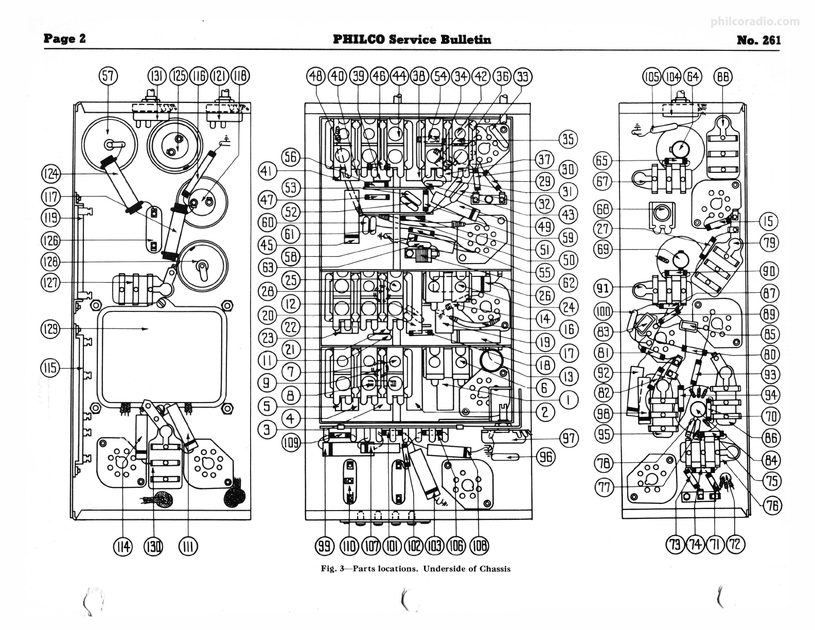
FiguresIn blacktypeIndicateclrded flguree In BaseView. Prices Subject to Change Without Notice.
Schem . Part
No. Dnerlptlon No,
Tube Shield Base ... . . . . . . . . . . . . . . . . 28-3898
Tube Shield (6N7G) .......... ... .... 8005
Tube Shield Base (6N7G)°. .. .... ..... 8004
Mtg. Grommet (R . F. Unit) . ....... .. 27-4317
Mtg. Sleeve (R . F . Unit) ... -.. . .. . .... 28-2257
Mtg . Screw (R. F . Unit) ....... .... .. W-729
Mt g. Spacer (R. F. Unit) code 121... . 27-8339
Mtg . Spacer (R. F. Unit) code 122. .. . 27-7807
Mtg . Washer ........... . .. . ...... .. 28-3927
Mtg. Rubber (Tuning Condense r) .... . 27-4325
Mtg . Rubber (Chassis) .... 3558
Mtg. Bushing . ... .... . ... , . . . .. . ... 27-4360
Mtg. Plate (R. F. Transformer) ..... . . 28-3808
Mtg . Spacer (R. F. Transformer) ... .. 27-8228
Mtg. Screw (R.F. Transformer) ..... . W-1635
Terminal Panel (Ant .). . . ... . . . . . . . . . 38-7714
Terminal Cover (Speaker) . . . .....•... 36-3672
Knob (Tuning) ................ .. .. . 27-4330
Knob, Vernier ..... . .. . ........•.... 27-4331
Knob, Tone & Volume ..... ...... . ... 27-4332
Knob , Range Switch.. . . . . . . . . . •. . . . 27-4326
Cable (Speaker) ..... . . .. .... . .•. ... 41-3223
A. C. Plug & Cord . . .. . . . • . . . . . •. . . . L-2288
Fuocs .. . . .. .. . . . . . . . . . . . . . . . • . . . . . . 45-2Q46
Bottom Shield Plate ..... . .... . .•.... 38-8143
Snap Fasteners. . . . . . . . . . . . . . .. .. . . . 28-4279
Speaker (U-15) ..................... 36-1252
CODE 121
Dial. . . . . . . . . •. . . . . . . . . . . . . . . . . . . . . 27-5249
Hub .. ... ......... . ........ . ...... 28-7187
Clamp. . . .. .. . . . . . . . . . . . . . . . . . . . . . . 28-2837
Set Screw .... .. .... . . . .... ......... W-1641
Dial Screen Holder Assembly . . . .... . . 31-1945
Drive Mtg . Asaembly ................ 31-1901
Vernier Drive ..... 31-1895
Gear (Dial). . . . . . . . . .. . . . . . . . . . . . . 28-7186
Thrust Spring. .. . . .. . . . . . . . . . . . . . . . 28-8611
,:hr,ust Washer .. . . . 28-3976
C Washer . ....... 28-3904
Gear (Drive) . . . . . . . . . . . . 31-1884
Mask. . . . . . . . . . . . . . . . . . . . . . . . . . 27-6206
Mask Arm & Link Assembly .... . . .. . 31-1899
Mask Washer ... . .......... ... . . ... 27-8318
Mask Guide & Bracket 38-7876
Pilot Lamp Assembly . ..... . ......... 38-7909
Bezel Frame & Plat e Assembly ... . . . . 40-5948
Glass. . . ... . . . . . . . . 27-8300
Ring .. . . . . . . . . . . . . . .. . . . . . . .. . 28-3988
Gasket . . . . . . . . . . . 27-8313
CODE122
Dial Escutcheon Assembly .......... .
Auto Dial Tuning Assembly Complete
Dial Scale .......... . ............. .
Dial Screen Hold er Assembly . .. ... . .
Gasket (Dial Scale) .. . . . . ....... ... .
Mask & Link Assembly .... ... . . . . . .
Mask Guide ....... . ..... . ... . . . . .
Ring (Retaining Mask Assembly) ... .
Spring (Reta ining Mask AABembly).
Contro l Screw .... .... . .... .
45-2324
31-1886
27-5207
31-1946
27-8398
45-2328
28-4118
28-7195
28-8629
31-1898
Ran ge Swit<\h Shaft Coupling .... 28-7198
Felt Wash er .. .
Wash er ...... .
Snap Fastene r .....
Control Handl e . .
Cover (Handl e) ....... . .
Set Screws (Handle) .
& rews (Cover) . . ......... . . .
Flood Lamp Assembly (single)
Pilot Lamp AASembly .
Bezel Assembly .
Bezel Gask et ..
Screws .......... .
Rt.~tion Tah Kit ........... ..... .. .
Insulator Rin g and Contact Assemb ly.
27-8399
W-495
28-4279
45-2329
28-4077
28-ij493
W-1669
38-7937
38-8051
40-5980
27-8517
W-480
40-6013
27-8351
Ll1t
Price
$0.03
.10
.03
.04
.01
.450
.400
.soc
.01
.02
.03
.04
.02
.01
.30C
.15
.15
.10
.10
.10
.10
.40
.05
.76 C
16.00
.40
.12
.10
.02
1.80
.10
.01
.300
.01
.25
.30
.50
.soc
.25
.40
.80
.06
.45
.01
25.00
.80
.01
.25
.20
.04
.15
.30C
.30C
.750
.25
.02
.40C
.35
1.00
.55C
.90
Ylew.REDUCEDPRICES
on PHILCO VIB·RATORS
Oct . 2, 1936
-s4.2s
Now Only List ... (formerly $5.00)
Part No. 41-3186 .... For all Philco sets up to 1936
Part No. 41-3170 .... For 1936 Philcos and most other malces
PHILCO RADIO & TELEVISION CORPORATION
·Parts and Service Division Printed in U.S.A.
/
philcoradio.com
Other Philco Radio manuals