®
,-- ---t-1}
"
I.F.•460 KC.
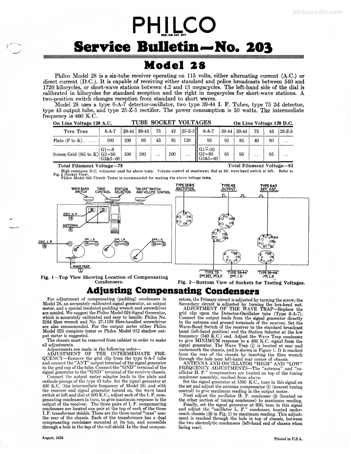
Fig. 3-Sc hem at ic Wiring Diagram
REPLACEMENT PARTS-
MODEL 28
No.on
Flis. Description Part No. Llat Price
Each
I
Cf)
Condenser (.00125 mfd.-Mica) . . ...... ... ...... 58S6
Wave:Trap . ...... . ... ...... .. .. . ... ... ... .... 3/HI050
Resistor (10,000 ohms) (Brown-Blo ck-Orange) .... 33-1000
Antenna Tr ansformer . . ........ ....... . ... ... .. 32-1360
Wave Band Switch .... ..... . .... . . .. . ......... 42-1062
Conden,er (.25 m!d.-Tubular) ........ . ..... . . .3()-4146
Tunin g Conden ser A!!embl;v. . .... .. ..• . . ..... .31·-1366
Compensating Conden ser (Antenna). . . . . . . . . . . .Part of CD
Condenser (.1 rnfd.-Tubular) . ..... ...... .. .... 30--4122
Resistor (400 ohms-Flex .) (Yellow-Black-Brown). 33-3016
Cond enser (.1 mfd.-Tubular ) ......... . ........ 3()-4122
Resistor (120.000 ohms) (Brown-R ed-Yellow).... .33-1128
Condenser (.003 mld .-Mi ca) . . .. . .............. 30-1028
Compensating Condenser (Osc. H . F. ) .. . . .. .. . .. Part of CD
Oscillator Tra nsformer .............. .. . ........ 32-1361
Condenser (.0008 mld.-Mi ca) ... . .... . ......... 5878
Resist.or (10,000 ohms) (Brown-Black-Orange) .. . .3524
Compensating Condens er (Osc. L. F .) ........... 04000S
Comp ensatin g Cond enser (1st I . F . Prim ary) ... . .Part of @
First I. F. Transformer ....... . ..... .. . ... ... . .32-1362
Compensating Condens er (1st I. F Secondary) ... . Part of@
Resistor (200 ohms-Flex. ) (Red-Black-Black) ... .7217
Condenser (.1 mfd.-Tubnl ar) .. . .. . ........... .3()-4122
Condenser (.09 mld.-Twin -Bakelite Block) . . ... .4989M
Resistor (15,000 ohms) (Brown-Gr een-Orange) •... 6208
Resistor (.1 meg.) (Whit e-White-Orange) ...... .. 4411
Compensating Conden ser (2d I. F. Primary) •. . •. .Part of@
2d I. F. Transformer ... .... .. ...... .... . .. .... 32-1363
Compensating Condenser (2d I. F. Secondary) ... .Part of@
Compensating Condenser (3d I. F . Primary) .. . ... Part of@
3d 1. F. Transformer ...... .............. ...... 32-1364
Compensating Condenser (3d I. F.
Set-ondary) ........ . ...... ..... .Part of@
@
8 Conde nser (.05 mld .-TubularJ ..... 3()-4()2()
@ Resistor (1000 ohms) (Brown-Bla, ·k- .35
Red) ....... . ... ............... 5837
~
Resistor (2 megs.)(Red-Black-Green) 5872
@ Condenser (.0001 mfd.-Twin-Bak,-
lite Block) ....... . .. . ...... ·.... 8035E
@) Resistor (50,000 ohms) (Green-
Brown-Orange) .............. ... 4518
@) Volume Control and On-Off Switch
(350,000 ohms, tapped at 75,000).. 33-5066
@ Resistor (10,000 ohms) (Brown-
Black-Ornn ge) ................. 33-1000
i
~
43
Condenser (.05 mfd .-Bakelit e Block) 3615- BU
~
Condenser (.01 mfd.-Tubul nr) . . .. .30-4124
Condenser (.00025 mfd.-Mica) .... 5858
Resistor (1 meg.) (Brown-Black-
Green) . ..... . ...... ..... . ... .4409
@ Resistor (.5 meg.) (Yellow-Wbite-
Yellow) . . .. ..... .. ... .. . ...... 4517
ICondenser (.1 mfd.-Tubulnr) .... . .3()-4122
46 Condenser (.25 mfd.-Tubular ).. ... 3o-4146
47 Condenser (.00011 mfd.-Mi caJ... .. 30-1031
@ Condenser (.0'2mfd.-Mi ca) . . ... .. 30-4113
@ Resistor (.25 meg.) (Red-Yellow-
Yellow) ... .. .. ............. . .. 4410
@) Resistor (.5 meg.) (Yellow-White-
Yellow) ... ... . . ........ . .. .. . .4517
.25
.25
.25
.25
1.45
.25
.35
.25
.35
.25
.25
.35
.40
.35
.30
.25
.25
S0.35
.50
.25
.60
1.10
.40
5.70
.35
.20
.35
.60
.65
.65
.35
.25
.35
1.50
.20
.35
.40
.25
.25
1.50
1.55
i
2
63
65
I
Resistor (50,000 ohms) (Green-B rown-Orang e) ... .4518
Condenser (.09 mfd.-Twin-Bnkelit e Block) . ... ... 4989M
Resistor (25,000 ohms) (Red-Green-Orange) . .. ... 33-1013
Tone Contro I (3-point)........ .. . .. . ........... 3()-4211
Condensers (In tone control) ..... . .....•...•. .. Inside @
Output Transformer (28CJ . ... ... ..... .. . . . .... 32-7243
Cond enser (.25 mfd.-Tubu hr) ................. 3()-4146
V . C ·1 d C A bl lP-21. ... .. ...... 02861
oice 01 an one ssem y K-27 .••.•. .. . . .36-3159
Field Coil and Pot Assembly P-21. · · · · · · · · · · .3&-3357
K-27.. ...... . .. 36-3352
Pilot I.amp . . ... . ............... . .... .. ....... 4567
Resistor (Wire Wound , New Type)(37 , 63, 29 obms)33-3!59
Filt er Choke .............. .. .. .. . . .. ... .. .. ... 6658
Filter Choke ... .... . .. . . . ... ..... .. .. . .... . ... 32-7018
Condenser (.05 mfd.-Tul,ular) . ..... .......... ,3()-4123
Conden ser (Electrolytic 6 and 12 mid., 150 volts) .. 30- 2083
Resistor (Wire Wound , New Typc)(lO, 137 ohms) 33-31 58
Condenser (.09 mfd.-Tubular) .......... ... . ... 3()-412:l
Condenser (Electrolytic 6 and 12 mid ., 150 volts) . .30-2083
Five-prong Socket ... . ............ . ...... .. . . . .7546
Six-prong Socket .... . . . . ....... .. . ......... . .. 7547
Seven-P.rong Socket . ..... . .. . . . ... .. . . ....... . .27-6005
Knob (large) . .... .......... . . . . ............. .27-4051
Knob (small) ... . .. ... ............ . ...... . .... 27-4052
Dial Assembly ....... . ..... . ..... .. ..... . ..... 31-1208
Speaker So,,ket (Ezcept 28C) ........ . ... . .. .. .. 4957
A.C . Cord and Plug Assembly . . . .... . . .. ....... lr943A
Chassis Mounting Screw . ........•. . ..... .. . . . .W-134,5
Chassi s Mounting Washer .. . ...... . ..... . ...... ~2089
Chassis Mounting Foot. ... ...... . . . ... . . . . .... 27-4116
Chassis Mounting Foot Plate ... .. ........... . .. 27-7497
Back Cover (28-C only) ..... . ...... .. ... ... . . .. ~2006
Bottom Shield Plate. . .. . . . . .. .. . .. . . . .. .. . . .W-200li
S0.25
.40
.25
.75
1.10
.40
.65
.80
3.50
4.00
.35
1.50
1.50
.35
1.70
,45
.35
1.70
.11
.11
.11
.10
.10
.45
.10
.60
2.75C
.35C
.05
.35C
.50
.30
+