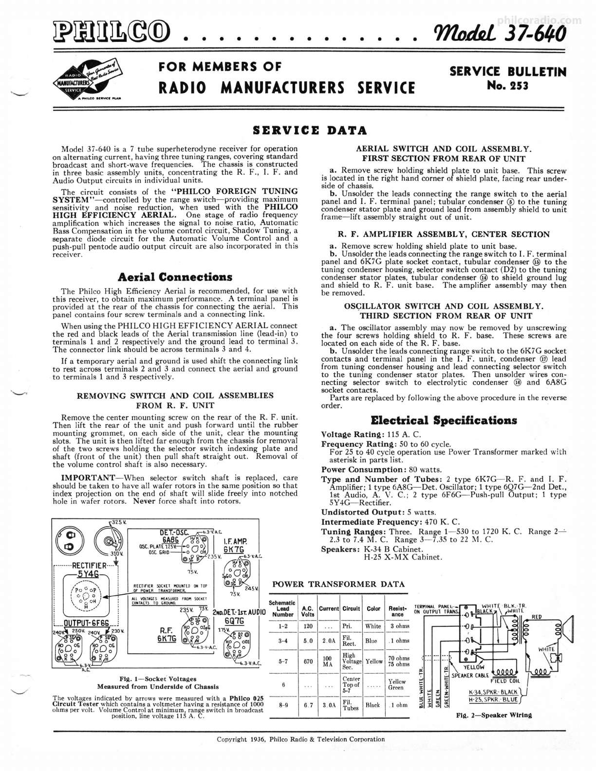
Page4 PHILCO Parts and Service Division No. 253
2No.DET.
1ST.AUDIO
8Q7G
SLOWINGBEAM
INDICATOR fRONl or CHA:.51S
@DSC.I
18H.C.
~
0SC.·1M.C.
(@R.f.
18M.C.
@ANT.I
18M.C.
FIii,. 5-Dlal Calibration FIii,. 6-Locatlon of I. F. Compensators FIii,. 7-Locatlons of R . F. Compensators
Alignment of Compensators
The accurate adjustment of the various compensating condensers iR vital to the
proper functioning of this receiver . There are four compensating condensers in
the I. F. Circuit, four in the Oscillator Circuit, three in the R . F. Amplifier Circuit
and three in the Antenna Circuit. Incorrect adjustment will cause loss of sensitivity,
unsatisfactory tone, and poor selectivity.
To accurate ly adjust this receiver, precision test equipment is necessary , A
signal generator such as the PHILCO MODEL 088 SIGNAL GENERA TOR ,
covering from 110 to 20,000 K. C. is recommended for adjusting the compensators
at the various frequencies specified. A visual indication of the receiver output
is also necessary to obtain correct adjustment of the compensators . PHILCO
MODEL 025 CIRCUIT TESTER contains a sensitive output meter and is recom-
mended for these ad ju stments.
Philco Fibre Handle Screw-driver No. 27-7059 completes the necessary equipment
for these adjustments. The locations of the various compensators are shown in
Figs. 6 and 7.
The following procedure must be observed in adjusting th e compensators:
DIAL CALIBRATION - In order to adjust this receiver correctly, the dial
must be aligned to track property with the tuning condenser. To do this, rotat e
the tuning condenser control to the extreme counter-clockwise position (maximum
capacity). Loosen the screw of dial hub, then turn dial until the glowing indicator
is centered on the first index line of dial scale (see Fig. 5). Now tighten the dial
hub set screw in this position.
SHADOW METER ADJUSTMENT-Remove aerial and allow tubes to warm
up . Then adjust shadow meter as follows:
1-Move the Shadow meter coil backwards and forwards, until the shadow is
within one-eighth of an inch of each side of the screen.
2-Remove the Rectifier tube from its socket, and rotate the shadow meter coil
for minimum shadow width .
3-Replace the Rectifier tube. The shadow should then return to maximum width
or within one-eighth of an inch of each side of the screen. If the shadow does
not return to maximum width, operations 1 and 2 should be continued until
it does .
OUTPUT METER -The 025 Output Meter is connected to the plate and
cathode terminals of one (6F6G) tube. Adjust the meter to use the (0-30) Volt
Scale.
During the I. F . and R. F. adjustments, the signal generator output sttould be
maintained at the lowest possible level that will give an indication on the output
meter. INTERMEDIATE FREQUENCY CIRCUIT
Frequency 470 K. C.
I-Connect the 088 Signal Generator output lead , through a .1 mfd. condenser,
to the control grid of the 6A8G tube; and th e ground connection of the output
lead to the chassis.
2-Set the range switch in position No. 1 (Broadcast), then rotate the tuning
condenser of the receiver to the maximum capacity position (counter-clockwise),
and adjust the signal generator for 470 K. C.
3-Adjust compensators Os 2nd I. F. Sec., @p 2nd I. F. Pri., ~s !st I. F. Sec., and
<i;J)p 1st ·r. F. Pri. for maximum reading on output meter.
RADIO FREQUENCY CIRCUIT
Tunlnl!, Ranl1,e-7.3 to 22.0 M. C.
1-Remove the signal generator output lead from the grid of 6A8G tube, and
connect it through the .1 mfd. condenser to terminal No. 1 on aerial input
panel, and the generator ground lead to terminal No . 3, rear of chassis.
(a) Termina ls 2 and 3 of aeria l input panel must be connected with connector
link provided on the panel, during these adjustments.
2-Se t the tuning range switch in position No. 3 (Short Wave) . Turn the signal
generator and receiver dials to 18 M. C. and adjust compensators @b Osc.,
(i)b R. F. and @b Ant. for maximum output (see note (a) below).
(a) The adjustment of the Radio Frequency compensator on the high frequency
range causes a slight detuning of the oscillator circuit. In order to overcome
this detuning effect , connect a variable condenser of approximately 350 mmfd .,
having a good vernier drive, across the oscillator section of the tuning condenser.
Leaving the signa l generator and receiver dials at 18 M. C., tune the added
condenser so that the second harmonic of the receiver oscillator will beat against
the signa l from the 088 signal gene rator bringing in the signal. The antenna
and R . F. compensato r @b and @b should then be adjusted to give maximum
output. Now remove the exte rn al condenser and turn compensator @b to
maximum capacity (clockwise) then without moving signal generator or receiver
tuning condenser, back off compensator @b (counter-clockwise) until a second
peak is reached on the output meter . The first peak is caused by tuning to
the image frequency signal and must not be used.
Tunlnl!, Ranl!,e-2.3 to 7.4 M. C.
I-Turn the range switch to position No . 2 (police). Rotate the signal generator
and receiver dials to 7.0 M. C. Then adjust compensator @a for maximum
output. Now turn the signal generator and receive r dials to 6.0 M. C. and
adjust compensators © a R . F. and © a Ant. for maximum reading on the
output meter.
Tunlnll. Ran 11,e-530 to 1720 K. C.
I-Set the range switch in position No. 1 (Broadcast). Set the 088 Signal Generator
indicator at 800 K. C. and the receiver dial at 1600 K. C.
(a) In adjusting the receive r at 1600 K. C. the second ha rm onic of 800 K. C.,
to which the signal genera tor is tuned, is used. The second harmoni c of 800
K . C. is 1600 K. C. Now adjust compensators @ Osc., @ R. F. and 0 Ant.
for maximum reading on output meter.
2-The low frequency end of the range is now tuned by turning the signal generator
and receiver dials to 600 K. C. and adjusting compensator ® Osc. series (see
Note (a) helow) for maximum reading on output meter.
(a) While compensator @ is being adjusted, the tuning condenser must be
rolled for maximum output. This is accomplished as follows: First tune com-
pensator (!!}for maximum output. Then vary the tuning conde nser for maximum
output at 600 K. C. Now retune compensator ® and again va ry the tuning
condenser back and forth at 600 K. C. for maximum output. This operation
of first turning the compensator then the tuning condenser is continued until
maximum output is obtained at the 600 K. C. frequency.
3-After the low frequency (600 K. C.) end of the range is adjusted, the 1600
K. C. end is readjusted , as given in Paragr aph (1) above, to correct any variation
that the low. frequency series com pensa tor ma y have ca used in the alignment
of the high frequency end .
4-Now turn the signal generator and receiver dials to 1500 K. C. and read just
compensato rs © Ant., and ® R. F., for maximum output.
NEW PROFITABLEBUSINESS
PHILCO
Noise-Elimination
Kit __,,,...,
for ALL SERVICEMEN
■ ■
■ ■
Part No. 45-
ListPrice S15.oo
June, 1936 Printed in U. S. A.