Fig.3-Dlagrarn
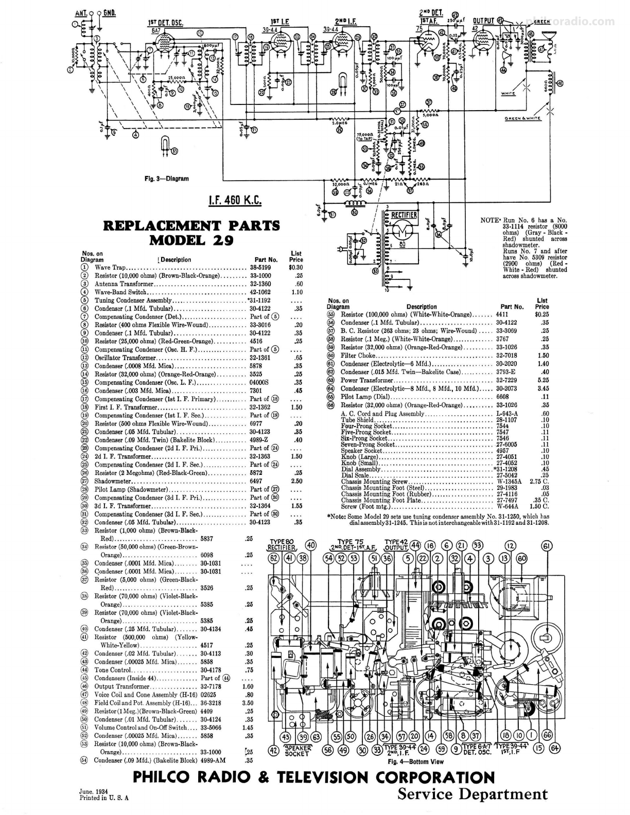
1.F.460K.C.
REPLACEMENT PARTS
MODEL 29
Nos. on
Diagram [Description Part No.
© Wave Trap ............ .. ..... ........... . . ........ 38-5199
@ Reaistor (10,000 ohms) (Brown-Black-Orange) . ........ 33-1000
@ Antenna Transformer ... .......... . . ........... .. ... 32-1360
© Wave-Band Switch... . .......... . ........ . .. .... .. . 42-1062
© Tuning Condenser Assembly .. ... .......... . ......... 031-1192
© Condenser (.1 Mfd. Tubular) ....... . . . . . . . . 30-4122
(D Compensating Condenser (Det.) ..... . . . . . . . . . . . . . . . . . Part of ®
® Reaistor (400ohms Flexible Wire-Wound)....... . .. 33-3016
® Condenser (.1 Mfd. Tubular). . . . . . . . . . . . . . . . . . . . . . . 30-4122
@) Resistor (25,000 ohms) (Red-Green-Orange) ..... , . . 4516
@ Compensating Condenser (Osc. H. F.) ....... .. . . .. . Part of©
@ Oscillator Transformer... .......... . . ... , .... 32-1361
@ Condenser (.0008 Mfd. Mica). . .. . . . . 5878
@ Reaistor (32,000 ohms) (Orange-Red-Orang e). . ....... 3525
@ Compensating Condenser (Osc. L. F.). ... .. . . .. . 04000S
@ Condenser (.003 Mfd. Mica) ... ..... ........ .... , .. . . 7301
@ Compensating Condenser (1st I. F. Primary) Part of@
@ First I. F. Transformer..... .. . .. .. .. .. .. 32-1362
@ Compensating Condenser (1st I. F. Sec.).. . Part of@
@) Reaistor (500 ohms Flexible Wire-Wound) .. . . 6977
@ Condenser (.05 Mfd. Tubular) .. . . . . . . . . . . 30-4123
@ Condenser (.09 Mfd. Twin) (Bakelite Block) . 4989-Z
@ Compensating Condenser (2d I. F. Pri.) .. .. . . . . Part of @
@ 2d I. F. Transformer ......... 32-1363
@ Compensating Condenser (2d I. F. Sec.). .... .. .. . , .... Part of @
~
!~1s::~te~.~-~~".'5~ _<~~--Bl.ack.•Green): : : : : : : : : : : : . ::!~
@ Pilot Lamp (Shadowmeter) .... . . . . . . . . . . . . . . . Part of@
@) Compensating Condenser (3d I. F. Pri.) . .. . . Part of @)
@) 3d I. F. Transformer....... . . . ...... .... . .. .... 32-1364
@ Compensating Condenser (3d I. F. Sec.) ... Part of@)
@ Condenser (.05 Mfd. Tubular) .... ................. ... 30-4123
@ Resistor (1,000 ohms) (Brown-Black-
Red)... .. ..... ... 5837 .25
@ Resistor (50,000 ohms) (Green-Brown-
Orange).. . . 6098
@ Condenser (.0001 Mfd. Mica).. . 30-1031
@ Qondenser (.0001 Mfd. Mica) 30-1031
® Resistor (5,000 ohms) (Green-Black-
Red)...... . 3526
@ Resistor (70,000 ohms) (Violet-Black-
Orange).. .. . . . . . 5385
@) Resistor (70,000 ohms) (Violet-Black-
Orange). . . . 5385
@ Condenser (.25 Mfd. Tubular). 30-4134
@ Resistor (500,000 ohms) (Yellow-
@
@
@
@
@
@
@
@
@)
®
@)
@
White-Yellow) 4517
Condenser (.02 Mfd. Tubular). 30-4113
Condenser (.00025 Mfd. Mica). 5858
Tone Control.. .. ........... 30-4178
Condensers (Inside 44) Part of @
Output Transformer .. 32-7178
Voice Coil and Cone Assembly (H-16) 02625
Field Coil and Pot . Assembly (H-16).. 36-3218
Resistor(! Meg.)(Brown-Black-Green) 4409
Condenser (.01 Mfd. Tubular) . . . . . . 30-4124
Volume Contr ol and On-OffSwitch .. . . 33-5066
Condenser (.00025 Mfd. Mica) . 5858
Resistor (10,000 ohms) (Brown-Black-
Orange)... .. .... . .. 33-1000
@ C~ndenser (.09 Mfd.) (Bakelite Block) 4989-AM
.25
.25
.25
.25
.45
.25
.30
.35
.75
1.60
.80
3.50
.25
.35
1.45
.35
~5
.35
List
Price
$0.30
.25
.60
1.10
.35
.20
.35
,25
.65
.35
.25
.35
.45
1.50
.20
.35
.40
1.50
.25
2.50
1.55
.35
NOTE• Run No. 6 has a No.
33-1114 resistor (8000
ohms) (Gray - Black -
Red) shunted acrosa
shadowmeter.
Runs No. 7 and after
have No. 5309 resistor
(2900 ohms) (Red -
White• Red) shunted
acrossshadowmeter.
Nos.on
Diagram De9Crlptlon PartNo.
@ Reaistor (100,000 ohms) (White-White-Orange) 4411
I
Condenser (.1 Mfd. Tubular) . . . . . . ......... 30-4122
B. C. Resistor (263 ohms; 23 ohms; Wire-Wound) . . . . 33-3069
Resist-Or
(.1 Meg.) (White-White-Orange)........ . .... 3767
I
~:rt~h~:~~-
~~~).
(Orang~R~d~~an~e~ ::: :: :::: . :::;~~:
Condenser (Electrolytic-6 Mfd.) ..... .. . ... ... . .... . . 30-2020
Condenser (.015 Mfd. Twin- Bakelite Case) ... ........ 3793-E
@ Power Transformer.... . .. ... 32-7229
@ Condenser (Electrolytic-8 Mfd., 8 Mfd., 10 Mfd.) ..... 30-2073
@ Pilot Lamp (Dial).... .. .. .. .. .. .. .. .. .. .. . .. .. .. .. . 6608
@ Resistor (32,000 ohms) (Orange-Red-Orange) .......... 33-1026
A. C. Cord and Plug Assembly.. . . . . . . . . . . .. .. . .. L-943-A
Tube Shield... .... ... ... ... . ......... .. . ........... 28-1107
Four-Prong Socket.. ....... .. . . . . . .. . . . . . . . . . .. .. .. . 754•
Five-Prong Socket ........ , .. . . .. . ... . . .... ..... . . .. 7547
Six-Prong Socket ................... ... .. .. ..... .... 7546
Seven-Prong Socket ........ . .. ... , • .... . ...••....... 27-6005
~eaker Socket ...... .... . ........ .. . . . . . . ..... . .... 4957
nob (Large)............... .. .. ..... ...... ........ 27-4051
Knob (Small) ........ .......... ... ...... .. .. ....... 27-4052
Dial Assembly...... . . . . . . .. .. . . .. . . . . . .. . .. .. . .*31-1208
Dial Seale.. . .. . . . .. . . . . . . . . .. .. .. . . . . .. .. . . .. .. .. . 27-5042
Chassis Mounting Screw. . .. ... .. . . . . . . . . • . . . . . . . . . . . W-1345A
Chassis Mounting Foot (Steel).. . .. . ... .• •... ........ 29-1983
Chassis Mounting Foot (Rubber) ...... ...... . ........ 27-4116
ChassIS Mountmg Foot Plate .. ...... ... . . . .. . ....... 27-7497
Screw (Foot mtg.) .. .. . . . .. .. . . . . . . W-644A
List
Price
S0.25
.35
.25
.25
.35
1.50
1.40
.40
5.25
3.45
.11
.35
.60
.10
.10
.II
.II
.II
.JO
.10
.10
.45
.25
2.75 C.
.03
.05
.35 C.
1.50 C.
*Note: Some Model 29 sets use tuning condenser assembly No. 31-1250,which has
dial assembly 31-1245. This is not interchan geablewith 31-1192and 31-1208.
PHILCO RADIO & TELEVISION CORPORATION
~~
S . D
Printed in U. S. A efVlCe epaftfileflt