• • • • • • • • model38-38,CodL121
SERVICEBULLETINNo. 290 lo, members ol
RADIO MANUFACTURERS SERVICE
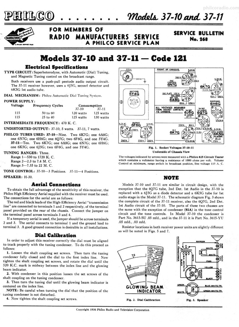
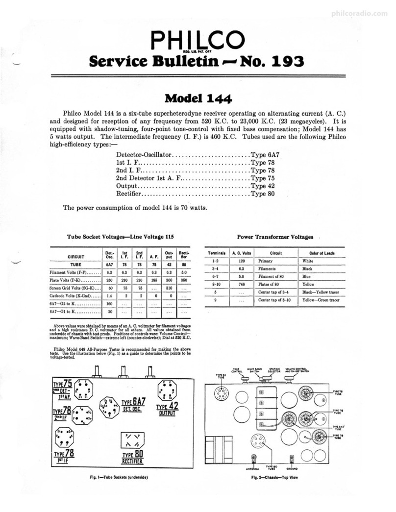
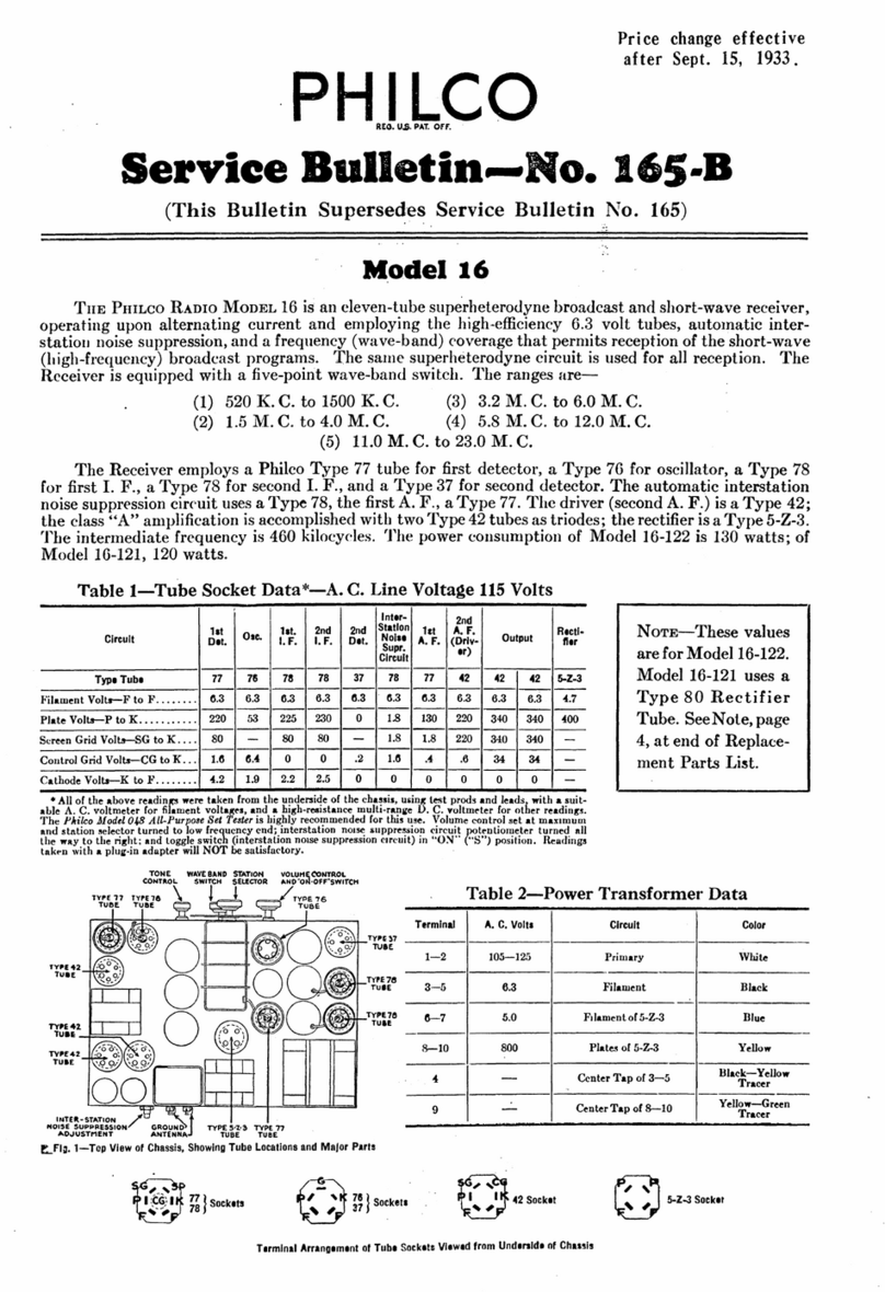
Electrical Specifications
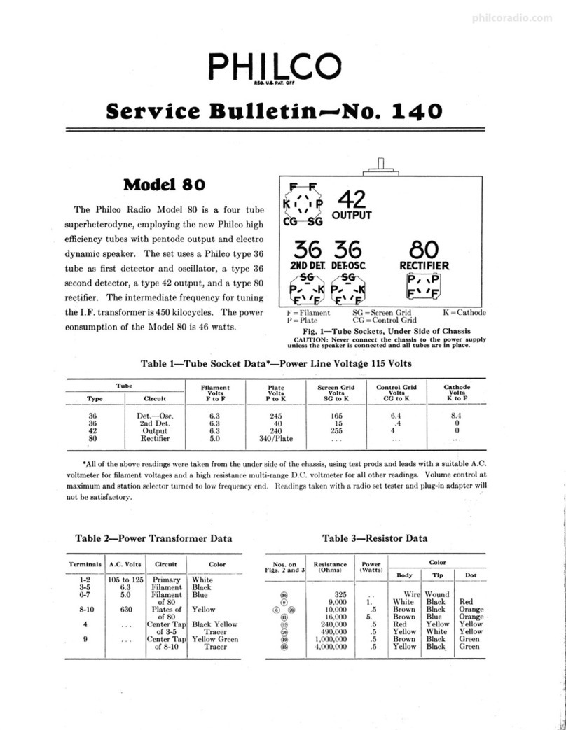
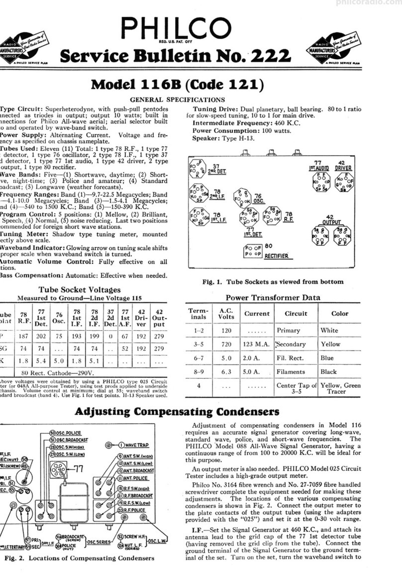
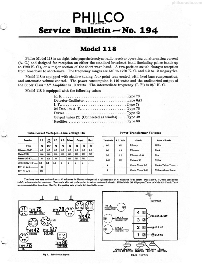
TYP ..: OF (.;IR CU JT : Six tube, battery opera ted superhelerody ne circuit, hav inJ.:
two liming rangC"s covering broadcast and sho rt- wave freciuencies; Automatic
\·111u111cControl: Tone Con tr ol, and a class " B" output stag<'.
INT ERMEDIATE FREQ UENCY: 470 K . C.
TUNING RANGES: Two - Range 1, 5.lO to 1720 K. C.
Range 2, $.7 to 18.0 M. C.
POWER OUTPUT: I watt.
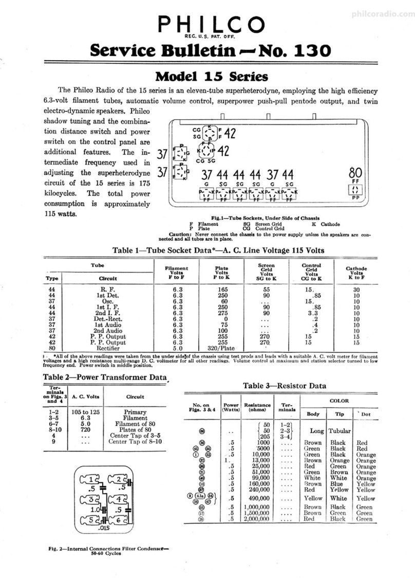
PHILCO TUBES USED: One 1C7G, 1st Det . & O,c.; one 1D5GT, I. F. amplifi er;
on,, 1H4(;, 2nd Del. (A.V.C.); one tE5GP, Isl Audi o ; one IH4G, Audio
Driver, and one IJ6 G, ou tput.
TYPE AER IAL : '"L"' type, Philco Part No. 45-2428.
CAB INETS AND SPEAKERS USED: Cahlnet
Type
BATTERIES REQ UIRED :
T
K
X
Speaker
Use d
KR26
HRlO
HRlO
"A" Batte ry: Two volt storage batte ry Philco t ype 172R or Dry "A"
hatt ery Philco Part No . 41-8011.
If a dry A l:!attery is used, a ballast lamp "type IFI" MUST be inserted in
t lie socke t provided in the (41-8011) batte ry. This lamp acts as a voltage regu lator
and maintains a constant potent ial of tw o vol ts on the filament of th e tubes .
"BC" Battery: Philco battery Part No. 41-8007 is used to supply "B" and
"C" voltages. This batter y con tains a soc ket into which the receiver battery cab le
plug is inserted.
Alignment of Compensators
EQUIPMENT REQ UI RED : (I ) Signal Generator, having a fun1amental
frequency range cove ring the tuning and int ermediate frequencies of th e receiver.
Philc o 11odel 07i A. C. opera ted Signal Genera tor or Model 088, battery operated
Signal Generator which have th e required frequency range .are the correct instru•
rnents for thi s purpose; (2) Output meter, Philco Model 026 circuit tester incor-
pora tes a sensitive ou tput meter and is recommended; (3) Philc o Fibre Handl e
Scr ew Driv er, Part -:,.Jo.17-i059 and Fibre \·Vrench, Part ~o . 316-t.
OUTPUT METER: The 0!6 Outpul ~Jete r is conn ected to the plate termin als
c,f ti1e lj 6G tube . Adju st the meLer to use th e (0-30) volt sca le and advance th e
atte nuat or contr ol of th e genera tor until a readable indicat ion is noted on th e
ou tput meter after sig nal is applied.
DIAL CALIBRATION: In order to adjust th e receiver correctl y t he dia l
must be aligned Lo track properly with th e tuning condenser. To adjust th e dial
proceed as follows:
1. Turn t he tuning condenser t o maximum capacity posit ion (p lates fu lly
meshed ).
2. Holding the tu nin g conde nser in thi s position, loosen the dia l clamp; th en
turn the dial until the indicator is ce nt ered on th e middle index line. Tighten clamp
1n thi s position. See Fig . 3 Cw
16A 168
'-._,/
7 7A
@)@@
Fi~. !. Locations of Co mp cnsators - Top of Chassis
1ST. AUDIO
~
A PHIi.CO Service Plan
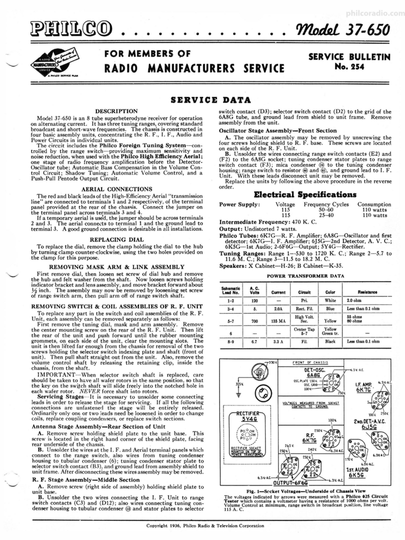
Fli, 1. Socket Voltaiies, Underside of Chassis
The vol tages indi cated by ar rows were measured with a Philco 026 Circuit Tester
which contains a sensitive vol tm eter. Volume Con tr ol at minimum, range switch
in broadcast position.
INTERMEDIATE FREQUENCY CIRCUIT
Insert th e signal genera tor shielded outp ut lead into the "Med" jack on the
panel of Lhe generator. Conn ect the other end of the output lead through a .I mfd.
condenser to the grid of th e IC7 G Det. Osc. tub e and the gro und connectio n of
th e sig nal generato r to the chassis. Set th e signa l generator and receiver co ntr ols
and ad 1ust the I. F. compensators as follow s:
I. Set Signal Generato r at 470 K. C. Turn "M ultiplier" Con trol to 1000
and adjus t the attenuato r for a readab le indication on th e outp ut meter.
2. Turn the receive r dial to 580 K. C.
3. Receiver Vo lume Control maximum.
4. Range Sw itch Broadcas t Po siti on.
5. Adju sl compensa lors (16B), (16A), (15B ) and (15A) for maximum output.
lf the ou tput metn goes off sca le when adjus ting the compensators retard signa l
genera tor "attenuator."
RADIO FREQUENCY CIRCUIT
1'.mlng Ran iie: 5;7 to 18 M. C.
I. With one end of th e shie lded lead of th e signal genera tor outp ut cable in
th e '"Med" jack, connect th e other end through a 400 oh m carbon resistor to the
"'Ant." termina l of the aerial panel of the receiver . The output lead ground must
be connected to the "G nd" terminal or to the chassis.
2. Set the controls and adjust the R. F . compensat ors as follows:
Volume Ranie Slinal Generator Compensators
Control Switch and Receiver Dial In Order
Max. 2 18 M. C. (4B) See Not e A
Tuning Range: 530 to 1720 K . C.
Remove the 400 ohm resistor fr om the generator outpu t cable and rep lace
with a 200 mmfd. conaenser. Then set the controls and adjust the compensators
as follows:
Volume
Control
Max.
Max.
Max.
RanJ!e
Switch
I
Signal Generator
and Receiver Dial
1500 K . C.
580 K . C.
1500 K. C.
Compen sators
In Order
(7A), (4A)
(7)
(7A), (4A)
NOTE A-T o accurately adjust t he high frequency oscilla tor co mpensator to
th e fu ndamental instead of the image signal, turn the oscillato r compe nsator to the
maximum ·capaci t y positi on (clockwi se). From this position slowly turn the com 4
pcnsator coun ter•clockwise until a seco nd maximum peak is ob taine d on the output
mete r. Adjus t the compe nsator for maximum outpu t using this second peak. The
first peak from maximum capacity position of th e compensator is the image signal
and mu st not be used in ad ju sting the compensator.
If the above procedure is correc tl y performed , the image sig na l will be found
(much weaker) by turning th e receiver dial 940 K. C. below the frequency :being
used on the high frequency range.
Copyright 1937 Philco Rad io & Television Corparation

