Contents
PHYTEC Meßtechnik GmbH 2006 L-681e_1
Preface............................................................................................................1
1Introduction............................................................................................2
1.1 Block Diagram.................................................................................. 4
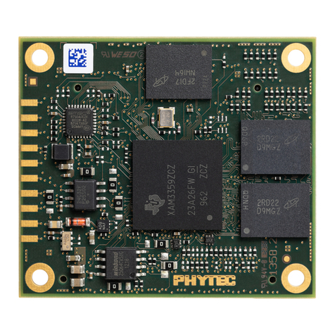
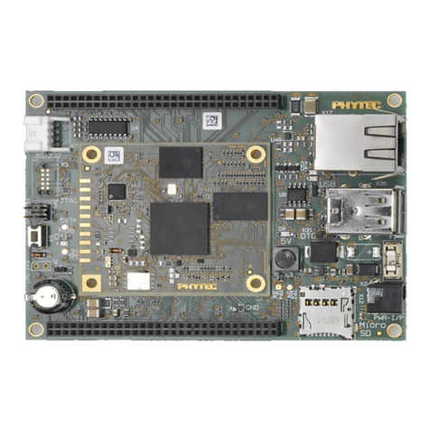
1.2 View of the phyCORE-LPC3180......................................................5
2Pin Description.......................................................................................7
3Jumpers................................................................................................17
3.1 J503 MCKO Signal........................................................................20
3.2 J504 A/D Positive Supply/Reference Voltage...............................21
3.3 J505 A/D Negative Supply/Reference Voltage ..............................21
4Power Requirements........................................................................... 22
4.1 Real Time Clock Battery ................................................................22
4.1.1 Real Time Clock Power Source (J506)..............................23
4.2 Voltage Supervision (U409)...........................................................23
5System Configuration..........................................................................24
5.1 Starting the phyCORE-LPC3180 ISP Mode...................................24
6System Memory ................................................................................... 25
6.1 Memory Model................................................................................25
6.2 SDR SDRAM (U602, U603)...........................................................26
6.3 NAND Flash Memory (U600)......................................................... 26
6.3.1 NAND Flash Write Protection Control (J604).....................27
6.4 I²C EEPROM (U601)......................................................................27
6.4.1 Setting the EEPROM Lower Address bits (J600, J601, J602)
...........................................................................................27
6.4.2 EEPROM Write Protection Control (J603).........................28
7Serial Interfaces................................................................................... 29
7.1 RS-232 Transceivers (U301, U302)...............................................29
7.1.1 UART2 Routing Jumpers J300, J301, J302 and J303.......29
7.2 USB Transceiver (U300)................................................................30
8Processor Independent Watchdog (U408).........................................31
8.1 Setting the Watchdog Timeout Period (J400)................................31
8.2 Interfacing the WDI Watchdog Input (J401)...................................32
9Debug Interface X201 .......................................................................... 33
10 Technical Specifications..................................................................... 36
11 Hints for Handling the phyCORE-LPC3180....................................... 38
12 The phyCORE-LPC3180 on the phyCORE-LPC3180 Carrier Board 39
12.1phyCORE-LPC3180 Carrier Board Peripherals............................. 39
12.1.1 Jumpers on the phyCORE-LPC3180 Carrier Board ..........42
12.2Functional Components on the phyCORE-LPC3180 Carrier Board45
12.2.1 Power Supply at X304........................................................45
12.2.2 Starting the LPC3180 Bootstrap Software......................... 45
12.2.3 Accessing UART5 through Socket P300A.........................46
