PI L-412.XX9025E1B Series User manual

L412M0015EN ‒ 3/14/2019
User Manual
L-412.XX9025E1B HIGH-LOAD LINEAR STAGE
MOTION | POSITIONING

Contents
1 Legal Information.........................................................................................................4
2 About this Document..................................................................................................5
2.1 Objective and Target Group..............................................................................5
2.2 Explanation of Symbols....................................................................................5
2.2.1 Typographic Conventions................................................................. 5
2.2.2 Symbols Used.................................................................................... 5
2.3 Figures................................................................................................................6
2.4 Downloading Manuals...................................................................................... 6
3 Safety............................................................................................................................7
3.1 Intended Use......................................................................................................7
3.2 General Safety Instructions.............................................................................. 7
3.3 Organizational Measures.................................................................................. 7
3.3.1 User Manual....................................................................................... 7
3.3.2 General Personnel Qualification.......................................................7
4 Product Description..................................................................................................... 8
4.1 Model Overview.................................................................................................8
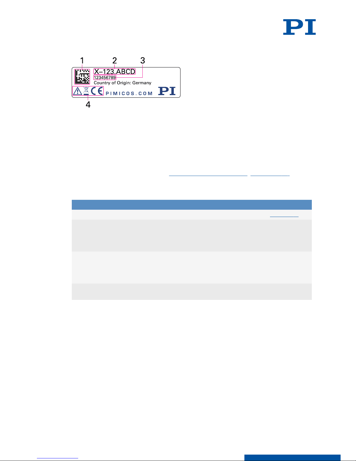
4.2 Product Labeling................................................................................................8
4.2.1 Type Plate........................................................................................... 9
4.3 Scope of Delivery...............................................................................................9
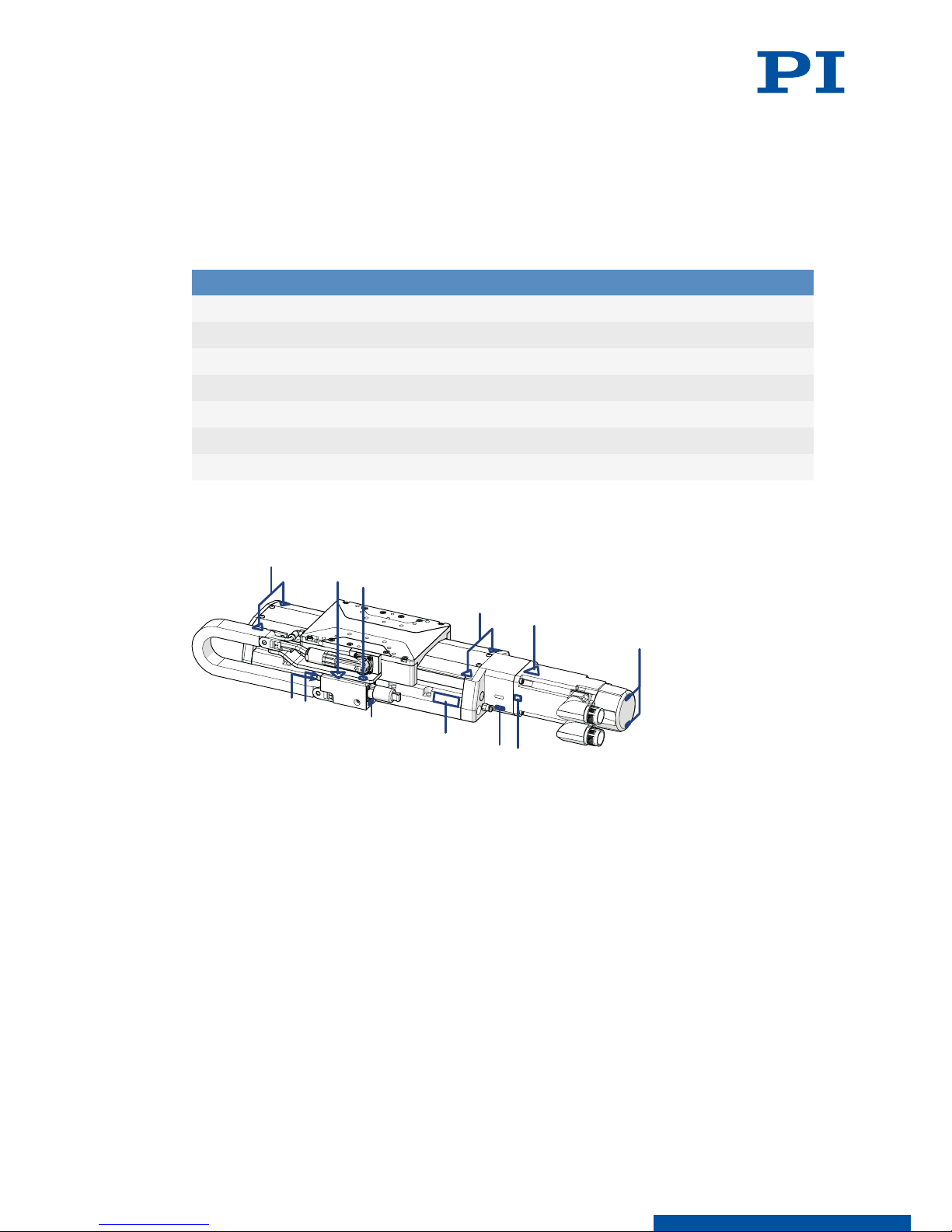
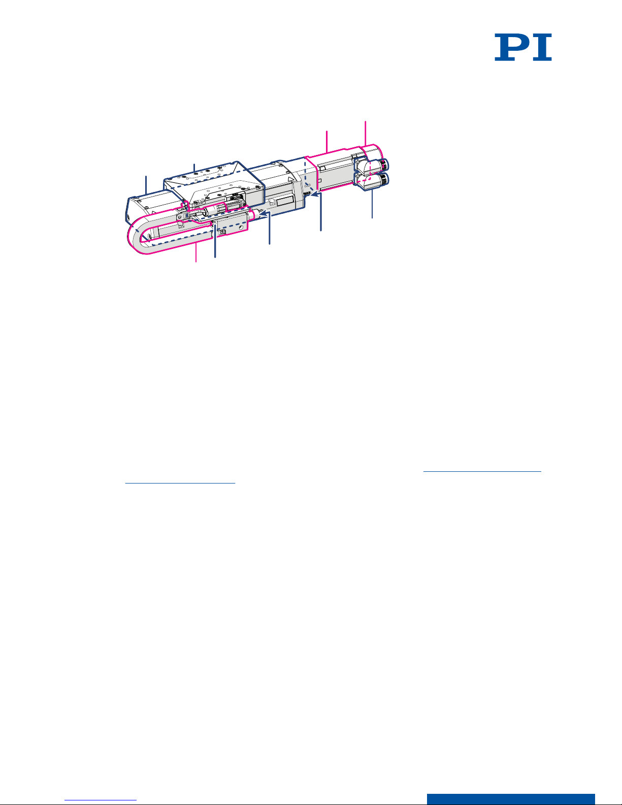
4.4 Overview.......................................................................................................... 10
4.4.1 Base Body......................................................................................... 10
4.4.2 Drive.................................................................................................. 10
4.4.3 Holding brake................................................................................... 11
4.4.4 Drag chain......................................................................................... 11
4.4.5 Linear Encoder Connector............................................................... 11
4.4.6 Purge Air System..............................................................................11
5 Unpacking.................................................................................................................. 13
6 Installation................................................................................................................. 14
6.1 Mounting the L-412.xx9025E1B.......................................................................14
6.2 Connecting the L-412.xx9025E1B to the Protective Earth Conductor.......... 15
6.3 Mounting the Load onto the L-412.xx9025E1B..............................................17
6.4 Connecting the L-412.xx9025E1B....................................................................18
7 Startup / Operation................................................................................................... 20
7.1 Starting and Operating the L-412.xx9025E1B................................................ 20
8 Maintenance...............................................................................................................22
8.1 Maintenance Run.............................................................................................22
8.2 Relubricating.................................................................................................... 22
8.3 Cleaning............................................................................................................22
8.4 Moving the Motion Platform by Hand........................................................... 23
CONTENTS L412M0015EN ‒ 3/14/2019
2MOTION | POSITIONING

9 Troubleshooting......................................................................................................... 24
10 Transportation............................................................................................................25
11 Customer Service Department.................................................................................26
12 Technical Data............................................................................................................ 27
12.1 Specifications...................................................................................................27
12.2 Maximum Ratings........................................................................................... 30
12.3 Ambient Conditions and Classifications........................................................30
12.4 Dimensions...................................................................................................... 31
13 Old Equipment Disposal........................................................................................... 33
14 Appendix.................................................................................................................... 34
14.1 Pin Assignment................................................................................................34
14.1.1 Drive Connector............................................................................... 34
14.1.2 Motor encoder..................................................................................34
14.1.3 Encoder connector...........................................................................36
14.2 PTC Temperature Sensor................................................................................ 36
14.3 Commutation Encoder.................................................................................... 37
14.4 Holding Brake Specifications..........................................................................37
15 EU Declaration of Conformity...................................................................................38
CONTENTS L412M0015EN ‒ 3/14/2019
3MOTION | POSITIONING

1 Legal Information
The following company names and brands are registered trademarks of Physik Instrumente
(PI) GmbH & Co. KG:
PI®, PIC®, NanoCube®, PICMA®, PIFOC, PILine®, NEXLINE®, PiezoWalk®, PicoCube®,
PiezoMove®, PIMikroMove, NEXACT®, Picoactuator®, PInano®, NEXSHIFT®, PITOUCH®,
PIMag®, PIHera, Q-Motion®
The patents held by PI can be found in our list at http://www.physikinstrumente.com/en/
about-pi/patents.
EnDat is a trademark of Dr. Johannes Heidenhain GmbH.
© 2019 Physik Instrumente (PI) GmbH & Co. KG, Karlsruhe, Germany. The text, photographs,
and drawings in this manual are protected by copyright. With regard thereto, Physik
Instrumente (PI) GmbH & Co. KG reserves all rights. The use of any text, images and
drawings is permitted only in part and only when indicating the source.
Original instructions
First print: 3/14/2019
Document number: L412M0015en, ASt
Subject to change. This manual is superseded by any new release. The latest versions of the
user manuals are available for download (p. 6) at www.pi.ws.
Publisher:
PI miCos GmbH
Freiburger Strasse 30
79427 Eschbach
Germany
www.pi.de
Customer service department:
Physik Instrumente (PI) GmbH & Co. KG
Auf der Roemerstrasse 1
76228 Karlsruhe
Germany
www.pi.de
1 LEGAL INFORMATION L412M0015EN ‒ 3/14/2019
4MOTION | POSITIONING

2 About this Document
2.1 Objective and Target Group
This user manual contains the information needed for the intended use of the
L-412.xx9025E1B.
Basic knowledge of closed-loop systems, motion control concepts, and applicable safety
measures is assumed.
2.2 Explanation of Symbols
This chapter explains the symbols and markings used by PI in their user manuals.
2.2.1 Typographic Conventions
Symbol / Label Meaning
1.
2.
Action consisting of several steps whose sequential order must be ob-
served
■ List item
p. 5 Cross-reference to page 5
RS-232 Labeling of an operating element on the product (example: socket of
the RS-232 interface)
Start > Settings
Menu path in the PC software (example: to open the menu, the
Start
and
Settings
menus must be clicked successively)
POS? Command line or a command from PI's General Command Set (GCS)
(example: command to get the axis position)
Device S/N
Parameter name (example: parameter where the serial number is stor-
ed)
5Value that must be entered or selected via the PC software
2.2.2 Symbols Used
Symbol / Label Meaning
General hazard symbol
DANGER
Dangerous situation
Failure to observe can lead to death or serious injury.
►Measures for avoiding the risk.
WARNING
Dangerous situation
Failure to observe can lead to serious injury.
►Action to take to avoid the risk.
2 ABOUT THIS DOCUMENT L412M0015EN ‒ 3/14/2019
5MOTION | POSITIONING

CAUTION
Dangerous situation
Failure to observe can lead to minor injury.
►Actions to take to avoid the risk.
NOTICE
Dangerous situation
Failure to observe can lead to material damage.
►Action to take to avoid the risk.
Information
Additional information on the L-412.xx9025E1B that can affect your application.
2.3 Figures
For better understandability, the colors, proportions and degree of detail in illustrations can
deviate from the actual circumstances. Photographic illustrations may also differ and must
not be seen as guaranteed properties.
2.4 Downloading Manuals
The latest versions of the user manuals can be downloaded (p. 6) at www.pi.ws.
For products that are supplied with software (data storage device in the scope of delivery),
access to the manuals is protected by a password. Protected content is only displayed on the
website after entering the access data. You need the data storage device for the product to
get the access data.
If a manual is missing or problems occur with downloading, contact our customer service
department (p. 26).
Downloading Manuals
1. Open the website www.pi.ws.
2. If the product was shipped with a data storage device: Log into the website:
a) Click Login.
b) Enter the login data.
The login data is in the [...]_Releasenews_[...].pdf in the Manuals directory on the
data storage device.
If necessary: Follow the link and register yourself to get the login data.
c) Click Login or press the Enter key.
3. Search for the product:
a) Click Search.
b) Enter the product number up to the period (e.g., L-412) into the search field.
c) Click Start search or press the Enter key.
d) If necessary: Click Load more results at the bottom of the list.
4. Click the corresponding product in the list of search results.
5. Click the Downloads tab.
➔The manuals are shown under
Documentation
.
6. Click the desired manual and save it.
2 ABOUT THIS DOCUMENT L412M0015EN ‒ 3/14/2019
6MOTION | POSITIONING

3 Safety
3.1 Intended Use
The L-412.xx9025E1B is a laboratory device as defined by DIN EN 61010-1. It is intended for
indoor use and use in an environment that is free of dirt, oil, and lubricants.
In accordance with its design, the L-412.xx9025E1B is intended for positioning, adjusting and
shifting loads in one axis at various velocities. The L-412.xx9025E1B is not intended for
applications in areas, in which a failure would present severe risks to human beings or the
environment.
The intended use of the L-412.xx9025E1B is only possible when completely mounted and
connected. The thermal protection sensor built into the L-412.xx9025E1B's motor must be
evaluated and monitored. The L-412.xx9025E1B must be operated with suitable electronics.
The electronics are not in the scope of delivery of the L-412.xx9025E1B.
The L-412.xx9025E1B may not be used for purposes other than those stated in this user
manual. The L-412.xx9025E1B may only be used in compliance with the technical
specifications and instructions in this user manual.
3.2 General Safety Instructions
The L-412.xx9025E1B is built according to state-of-the-art technology and recognized safety
standards. Improper use of the L-412.xx9025E1B may result in personal injury and/or
damage to the L-412.xx9025E1B.
►Use the L-412.xx9025E1B only for its intended purpose and if it is in perfect condition.
►Read the user manual.
►Eliminate any faults and malfunctions that are likely to affect safety immediately.
The operator is responsible for correct installation and operation of the L-412.xx9025E1B.
3.3 Organizational Measures
3.3.1 User Manual
►Always keep this user manual available with the L-412.xx9025E1B. The latest versions of
the user manuals can be downloaded (p. 6) at www.pi.ws.
►Add all information from the manufacturer such as supplements or technical notes to the
user manual.
►If you give the L-412.xx9025E1B to a third party, also include this user manual as well as
other relevant information provided by the manufacturer.
►Only use the device on the basis of the complete user manual. Missing information due to
an incomplete user manual can lead to serious or fatal injuries and damage to equipment.
►Only install and operate the L-412.xx9025E1B after you have read and understood this
user manual.
3.3.2 General Personnel Qualification
The L-412.xx9025E1B may only be installed, started up, operated, maintained, and cleaned
by authorized and appropriately qualified personnel.
3 SAFETY L412M0015EN ‒ 3/14/2019
7MOTION | POSITIONING

4 Product Description
4.1 Model Overview
High-load linear stage, xx mm travel range, 116 mm width, 400 N load capacity,
absolute linear encoder with EnDat 2.2 signal transmission, 1 nm sensor resolution,
drag chain, holding brake, synchronous servo motor, to 320 V
Product number Travel range: xx
L-412.039025E1B 52 mm (2")
L-412.059025E1B 102 mm (4")
L-412.099025E1B 204 mm (8")
L-412.139025E1B 305 mm (12")
L-412.179025E1B 407 mm (16")
L-412.219025E1B 508 mm (20")
L-412.259025E1B 610 mm (24")
4.2 Product Labeling
1
1
3
12
4
2
4
5
4
6
4
Figure 1: Product label on the L-412.xx9025E1B
1. Warning symbol: Risk of crushing
2. Connector labels
3. Warning symbol: Hot surface
4. Warning symbol: Electrostatic-sensitive device
5. Type plate
6. Protective earth connector
4 PRODUCT DESCRIPTION L412M0015EN ‒ 3/14/2019
8MOTION | POSITIONING

4.2.1 Type Plate
Figure 2: Type plate of the L-412.xx9025E1B
1. Data matrix code (example; contains the serial number)
2. Product number (example)
3. Serial number (example), individual for each L-412.xx9025E1B
Meaning of the position (counting from the left):
1 = internal information,
2 and 3 = year of manufacture,
4 to 9 = consecutive numbers
4. Warning and conformity symbols (old equipment disposal (p. 33), CE mark (p. 38))
4.3 Scope of Delivery
Product number Description
L-412.xx9025E1B Linear stage according to the order (p. 8)
For L-412.xx9025E1B with xx = 03, 05, 09, 13:
L412B0048
Mounting kit for mounting the
L-412.xx9025E1B, consisting of
■10 socket head screws, ISO 4762 M6×30
■2 dowel pins, ISO 8734, 4m6 × 12
For L-412.xx9025E1B with xx = 17, 21, 25:
L412B0049
Mounting kit for mounting the
L-412.xx9025E1B, consisting of
■16 socket head screws, ISO 4762 M6×30
■2 dowel pins, ISO 8734, 4m6 × 12
L412M0015 User manual for the L-412.xx9025E1B (this
document)
4 PRODUCT DESCRIPTION L412M0015EN ‒ 3/14/2019
9MOTION | POSITIONING

4.4 Overview
1
7
5
34
2
6
98
Figure 3: Elements of the L-412.xx9025E1B
1. Base body
2. Motion platform
3. Drive
4. Holding brake
5. Drive and rotary encoder connector
6. Purge air connector
7. Linear encoder connector
8. Grease nipple for relubricating the drive screw
9. Drag chain
4.4.1 Base Body
The base body is the basis of the positioner. The L-412.xx9025E1B is mounted onto a surface
via the base body (p. 14).
The base body comprises the following subassembly (subassemblies):
Drive screw
The drive screw converts the rotary motion of the drive to linear motion of the motion
platform.
Absolute linear encoder
Absolute encoders supply explicit position information that enables immediate
determination of the position. Therefore, no referencing is necessary when switching on.
The position is measured directly at the motion platform, which minimizes the influence of
mechanical play and deformation when measuring the position.
4.4.2 Drive
The drive generates the torque required for the dynamics of the motion platform.
4 PRODUCT DESCRIPTION L412M0015EN ‒ 3/14/2019
10 MOTION | POSITIONING

The drive comprises the following subassembly (subassemblies):
Motor
The motor generates the torque required for the dynamics of the motion platform.
Rotary encoder
The rotary encoder measures the motor shaft's angle of rotation. This signal can be used by
suitable electronics for commutating the motor .
4.4.3 Holding brake
The holding brake blocks the drivetrain at rest.
The holding brake is designed for holding only and is not suitable for continuous braking
during operation.
The holding brake blocks in a zero voltage state.
4.4.4 Drag chain
The drag chain (also: energy chain or energy supply chain) guides and protects the
L-412.xx9025E1B's flexible cables and lines.
4.4.5 Linear Encoder Connector
The linear encoder connector transmits the L-412.xx9025E1B's sensor signals.
4.4.6 Purge Air System
The purge air system protects the drive and guides of the L-412.xx9025E1B against
surrounding dust.
The purge air system comprises the following subassembly (subassemblies):
4 PRODUCT DESCRIPTION L412M0015EN ‒ 3/14/2019
11 MOTION | POSITIONING

Passive dust protection
The passive dust protection consists of covering strips that seal the openings on the side of
the L-412.xx9025E1B's base body and therefore reduces the amount of dust that can
penetrate.
Active dust protection
The active dust protection consists of a purge air connector on the base body of the
L-412.xx9025E1B, which creates a slight overpressure in the L-412.xx9025E1B and therefore
reduces the amount of dust that can penetrate.
4 PRODUCT DESCRIPTION L412M0015EN ‒ 3/14/2019
12 MOTION | POSITIONING

5 Unpacking
Unpacking the L-412.xx9025E1B
1. Unpack the L-412.xx9025E1B with care. Hold the L-412.xx9025E1B by its base body only.
2. Compare the contents with the scope of delivery according to the contract and the
delivery note.
3. Inspect the contents for signs of damage. If any parts are damaged or missing, contact
our customer service department (p. 26) immediately.
4. If the L-412.xx9025E1B was supplied with ESD protective caps on the connectors: Do not
remove the ESD protective caps.
5. Keep all packaging materials in case the product needs to be returned.
5 UNPACKING L412M0015EN ‒ 3/14/2019
13 MOTION | POSITIONING

6 Installation
6.1 Mounting the L-412.xx9025E1B
Overview
Figure 4: Mounting the L-412.xx9025E1B onto an underlying surface
Tools and Accessories
■Screw set for mounting the L-412.xx9025E1B (p. 9)
■Suitable screwdriver
Requirements
✓You have read and understood the general safety instructions (p. 7).
✓You have provided a suitable surface with the holes necessary for the screws and if
required, locating pins (p. 31).
■The flatness of the surface is ≤ 2 μm.
■For applications with large temperature changes: The surface should have the same or
similar thermal expansion properties as the L-412.xx9025E1B.
✓You have accounted for the space required to route cables without bending and
according to regulations.
DANGER
Risk of electric shock if the protective earth conductor is not connected!
If the protective earth conductor is missing or not properly connected, risk of dangerous
touch voltages on the L-412.xx9025E1B in the event of malfunction or failure of the system. If
there are touch voltages, touching the L-412.xx9025E1B leads to serious injuries or death by
electric shock.
►Connect the L-412.xx9025E1B to a protective earth conductor before startup.
►Do not remove the protective earth conductor during operation.
►If the protective earth conductor has to be removed temporarily (e.g., for modifications),
reconnect the L-412.xx9025E1B to the protective earth conductor before restarting.
6 INSTALLATION L412M0015EN ‒ 3/14/2019
14 MOTION | POSITIONING

CAUTION
Risk of crushing by moving parts!
Risk of minor injuries from crushing between the moving parts of the L-412.xx9025E1B or the
load and a fixed part or obstacle.
►Use safeguards to protect limbs in areas where they could be caught by moving parts.
►Maintain the safety distances according to DIN EN ISO 13857 when installing protective
structures.
NOTICE
Damage due to collisions!
Collisions can damage the L-412.xx9025E1B, the load to be moved, and the surroundings.
►Make sure that collisions are not possible between the L-412.xx9025E1B, the load to be
moved, and the surroundings in the motion range of the L-412.xx9025E1B.
►Do not place any cables or other objects in areas where they could be caught by moving
parts.
NOTICE
Excessively long screws and locating pins
Screws and locating pins that are inserted too deeply can damage the L-412.xx9025E1B.
►Pay attention to the depth of the mounting and locating holes (p. 32) in the
L-412.xx9025E1B.
►Only use screws and locating pins of the correct length for the respective mounting holes.
Mounting the L-412.xx9025E1B on a Surface
1. If necessary: Insert the locating pins into the corresponding holes in the surface.
2. Align the L-412.xx9025E1B on the surface so that the corresponding mounting holes in the
L-412.xx9025E1B and the surface are aligned.
3. Place the L-412.xx9025E1B onto the surface so that the locating pins can be inserted into
the corresponding locating holes of the L-412.xx9025E1B.
4. If necessary: Allow access to the mounting holes in the base body of the L-412.xx9025E1B.
Possible measures:
■Temporary startup of the L-412.xx9025E1B (p. 20) and commanding the motion
platform to a suitable position
■Push the motion platform by hand (p. 23)
5. Tighten the screws in all accessible mounting holes completely.
Recommended torque: 3 Nm
6. If necessary: Repeat steps 4 to 5 for all concealed mounting holes.
7. Check that the L-412.xx9025E1B is fixed firmly to the surface.
6.2 Connecting the L-412.xx9025E1B to the Protective Earth
Conductor
The L-412.xx9025E1B must be connected to the protective earth conductor via the drive
connector.
It is only necessary to connect the L-412.xx9025E1B's base body to the protective earth
conductor when both of the following conditions are met:
■The load on the motion platform must be connected to the protective earth conductor, but
it is not possible to connect the protective earth conductor directly.
■The load and the motion platform are connected conductively to each other.
6 INSTALLATION L412M0015EN ‒ 3/14/2019
15 MOTION | POSITIONING

Overview
Figure 5: Protective earth connector on the L-412.xx9025E1B
1. Connector for the protective earth conductor on the L-412.xx9025E1B, indicated by the
protective earth symbol
2. Safety washer
3. Flat washer
4. Protective earth conductor lug
5. Screw, ISO 7045 M4×8
Tools and Accessories
■Suitable protective earth conductor:
■Cable cross section ≥ 0.75 mm2
■Contact resistance <0.1 Ω at 25 A at all connection points relevant for attaching the
protective earth conductor
■Suitable screwdriver
Requirements
✓You have read and understood the general safety instructions (p. 7).
DANGER
Risk of electric shock if the protective earth conductor is not connected!
If the protective earth conductor is missing or not properly connected, risk of dangerous
touch voltages on the L-412.xx9025E1B in the event of malfunction or failure of the system. If
there are touch voltages, touching the L-412.xx9025E1B leads to serious injuries or death by
electric shock.
►Connect the L-412.xx9025E1B to a protective earth conductor before startup.
►Do not remove the protective earth conductor during operation.
►If the protective earth conductor has to be removed temporarily (e.g., for modifications),
reconnect the L-412.xx9025E1B to the protective earth conductor before restarting.
Information
►Observe the applicable standards for connecting the protective earth conductor.
Connecting the L-412.xx9025E1B to the Protective Earth Conductor
1. If necessary, attach a suitable cable lug to the protective earth conductor.
2. Attach the cable lug of the protective earth conductor to the protective earth connection
as shown in the illustration of the L-412.xx9025E1B.
3. Tighten the screw with a torque of 1.2 Nm to 1.5 Nm.
6 INSTALLATION L412M0015EN ‒ 3/14/2019
16 MOTION | POSITIONING

4. Make sure that the contact resistance is <0.1 Ω at 25 A at all connection points relevant for
attaching the protective earth conductor.
6.3 Mounting the Load onto the L-412.xx9025E1B
Overview
Figure 6: Mounting the load onto the L-412.xx9025E1B
1. Screws
2. Load
3. Motion platform of the L-412.xx9025E1B
Tools and Accessories
■At least 3 screws with suitable dimensions (p. 32)
■Suitable tool for tightening the screws
■Optional: 2 suitably dimensioned dowel pins as locating pins for aligning the load on the
L-412.xx9025E1B
Requirements
✓You have read and understood the general safety instructions (p. 7).
✓You have mounted the L-412.xx9025E1B on the surface (p. 14) properly.
✓The L-412.xx9025E1B is not connected to the electronics.
✓You have prepared the load so that it can be fixed to the mounting holes on the motion
platform:
■The distance between the center of gravity of the load and the center of the motion
platform is as small as possible in all directions.
■At least three points are provided for fixing the load on the motion platform.
6 INSTALLATION L412M0015EN ‒ 3/14/2019
17 MOTION | POSITIONING

NOTICE
Impermissibly high load on the L-412.xx9025E1B
An impermissible high load impairs the motion of the platform and can damage the
L-412.xx9025E1B.
►Pay attention to the maximum permissible forces (p. 27) that may act on the motion
platform.
►In the case of multi-axis systems, include the masses of the positioners to be moved
when calculating the load.
Fixing the Load
1. If necessary: Insert the locating pins into the corresponding holes in the motion platform.
2. Align the load on the motion platform so that the mounting holes selected in the motion
platform can be used for mounting the load.
3. Place the load onto the motion platform so that the locating pins are inserted into the
corresponding locating holes in the load.
4. Tighten the screws in all mounting holes.
5. Check that the load is fixed firmly to the motion platform.
6.4 Connecting the L-412.xx9025E1B
Tools and Accessories
■Suitable cable set
■If necessary: Suitable screwdriver for the locking screws of the connectors.
■Optional: Purge air connector with the following properties:
Pressure: 2 to 6 bar (200 to 600 kPa); purge air hose: Outer diameter 4 mm; air quality as
stated in the specifications (p. 27)
Requirements
✓You have read and understood the general safety instructions (p. 7).
✓You have read and understood the user manual for the electronics.
✓You have installed the electronics properly.
✓The electronics are switched off.
✓The L-412.xx9025E1B is connected to the protective earth conductor (p. 15).
NOTICE
Damage due to incorrect connection of the L-412.xx9025E1B!
Connecting unsuitable electronics or the wrong cable can lead to damage to the
L-412.xx9025E1B or the electronics.
►Make sure that the electronics support the drive type of the L-412.xx9025E1B and has
been configured accordingly.
►Use cables from PI miCos only to connect the L-412.xx9025E1B to the electronics.
►Pay attention to correct pin assignment (p. 34).
Connecting the L-412.xx9025E1B
1. If necessary: Remove the ESD protective caps from the connectors of the
L-412.xx9025E1B.
2. All of the L-412.xx9025E1B's connections must be made in the following order:
a) Optional: Purge air connector
6 INSTALLATION L412M0015EN ‒ 3/14/2019
18 MOTION | POSITIONING

Permissible pressure: 2 to 6 bar (200 to 600 kPa)
b) Rotary encoder connector
c) Drive connector
d) Linear encoder connector
3. Secure the connectors against unintentional removal.
4. If necessary: Turn the drive and encoder connector carefully to a position suitable for your
installation conditions.
The drive and encoder connector of the L-412.xx9025E1B can be turned up to 180° (in
steps of approximately 7°).
≈7°
Figure 7: Rotation range of the L-412.xx9025E1B's drive/sensor connectors
6 INSTALLATION L412M0015EN ‒ 3/14/2019
19 MOTION | POSITIONING

7 Startup / Operation
7.1 Starting and Operating the L-412.xx9025E1B
Requirements
✓You have read and understood the general safety instructions (p. 7).
✓For startup with a load or in a multi-axis system: You have installed the L-412.xx9025E1B
properly (p. 14).
✓The L-412.xx9025E1B is connected to the protective earth conductor (p. 15).
✓You have read and understood the user manual for the electronics used.
✓If a digital controller is used: You have read and understood the manual for the PC
software used.
✓The electronics and if required, the PC software, have been installed (see the user manual
for the electronics).
DANGER
Risk of electric shock if the protective earth conductor is not connected!
If the protective earth conductor is missing or not properly connected, risk of dangerous
touch voltages on the L-412.xx9025E1B in the event of malfunction or failure of the system. If
there are touch voltages, touching the L-412.xx9025E1B leads to serious injuries or death by
electric shock.
►Connect the L-412.xx9025E1B to a protective earth conductor before startup.
►Do not remove the protective earth conductor during operation.
►If the protective earth conductor has to be removed temporarily (e.g., for modifications),
reconnect the L-412.xx9025E1B to the protective earth conductor before restarting.
CAUTION
Risk of crushing by moving parts!
Risk of minor injuries from crushing between the moving parts of the L-412.xx9025E1B or the
load and a fixed part or obstacle.
►Use safeguards to protect limbs in areas where they could be caught by moving parts.
►Maintain the safety distances according to DIN EN ISO 13857 when installing protective
structures.
CAUTION
Burning due to hot surface!
The drive of the L-412.xx9025E1B and the surroundings can heat up during operation.
Touching the drive and surrounding parts can result in minor injuries from burning.
►Make sure that the hot drive and the surrounding parts cannot be touched.
NOTICE
Operating voltage excessively high or incorrectly connected!
Operating voltages that are too high or incorrectly connected can cause damage to the
L-412.xx9025E1B.
►Pay attention to the operating voltage range (p. 30), which is specified for the
L-412.xx9025E1B.
►Pay attention to correct pin assignment (p. 34).
7 STARTUP / OPERATION L412M0015EN ‒ 3/14/2019
20 MOTION | POSITIONING
This manual suits for next models
7
Table of contents
Other PI Industrial Equipment manuals
Popular Industrial Equipment manuals by other brands

ipf electronic
ipf electronic OT15 Series manual

Branick
Branick 5500 Installation, Operation and Repair Parts Information

eao
eao 09 Series Operating instructions and safety instructions

Pepperl+Fuchs
Pepperl+Fuchs IUH-F192-V1 Series quick start guide

ABB
ABB TPS 57D01 Operation manual

SAF-HOLLAND
SAF-HOLLAND Holland FWS1 Replacement manual