PI U--651 Series User manual

Physik Instrumente (PI) GmbH & Co. KG, Auf der Roemerstrasse 1, 76228 Karlsruhe, Germany
Phone +49 721 4846-0, Fax +49 721 4846-1019, Email info@pi.ws, www.pi.ws
MP136E
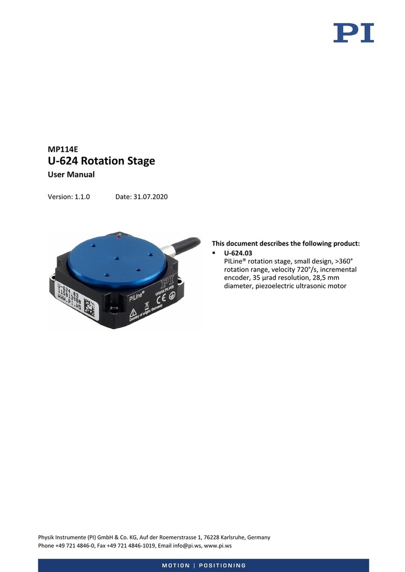
U-651 Rotation Stage
User Manual
Version: 1.3.0
Date: 02.12.2020
This document describes the following products:
U-651.03
Rotation stage with low profile and PILine®
ultrasonic piezo motors, >360° rotation range,
velocity 540 °/s, incremental encoder,
resolution 9 µrad, D-sub connector
U-651.03V
Rotation stage with low profile and PILine®
ultrasonic piezo motors, >360° rotation range,
velocity 540 °/s, incremental encoder,
resolution 9 µrad, D-sub connector, vacuum
compatible to 10-6 hPa
U-651.04
Rotation stage with low profile and PILine®
ultrasonic piezo motors, >360° rotation range,
velocity 540 °/s, incremental encoder,
resolution 4 µrad, D-sub connector
U-651.04V
Rotation stage with low profile and PILine®
ultrasonic piezo motors, >360° rotation range,
velocity 540 °/s, incremental encoder,
resolution 4 µrad, D-sub connector, vacuum
compatible to 10-6 hPa

The following company names and brands are registered trademarks of Physik Instrumente (PI) GmbH & Co.
KG:
PI®, NanoCube®, PICMA®, PILine®, NEXLINE®, PiezoWalk®, NEXACT®, Picoactuator®, PInano®, PIMag®,
Q-Motion®
The patents held by PI are found in our patent list: https://www.physikinstrumente.com/en/about-pi/patents
© 2020 Physik Instrumente (PI) GmbH & Co. KG, Karlsruhe, Germany. The text, photographs and drawings in
this manual are protected by copyright. With regard thereto, Physik Instrumente (PI) GmbH & Co. KG retains
all the rights. The use of any text, images, and drawings is permitted only in part and only when indicating the
source.
Original instructions
First printing: 02.12.2020
Document number: MP136E, CBo, Version 1.3.0
Subject to change without notice. This manual is superseded by any new release. The latest release is
available for download (p. 3) on our website.

1About this Document 1
1.1 Objective and Target Audience of this User Manual.................................................. 1
1.2 Symbols and Typographic Conventions...................................................................... 1
1.3 Definition of Terms..................................................................................................... 2
1.4 Figures ........................................................................................................................ 2
1.5 Other Applicable Documents ..................................................................................... 3
1.6 Downloading Manuals................................................................................................ 3
2Safety 5
2.1 Intended Use .............................................................................................................. 5
2.2 General Safety Instructions ........................................................................................ 5
2.3 Organizational Measures............................................................................................ 6
3Product Description 7
3.1 Model Overview ......................................................................................................... 7
3.2 Product View .............................................................................................................. 8
3.3 Product Labeling......................................................................................................... 8
3.4 Scope of Delivery...................................................................................................... 10
3.5 Suitable Controllers .................................................................................................. 10
3.6 Accessories ............................................................................................................... 10
3.7 Technical Features.................................................................................................... 11
3.7.1 Rotary Encoder ............................................................................................ 11
3.7.2 Reference Switch......................................................................................... 11
3.7.3 ID Chip.......................................................................................................... 11
4Unpacking 13
5Installation 15
5.1 General Notes on Installing ...................................................................................... 15
5.2 Connecting the U-651 to the Protective Earth Conductor....................................... 17
5.3 Mounting the U-651 onto a Surface......................................................................... 18
5.4 Fixing the Load to the U-651 .................................................................................... 20
5.5 Connecting the Vacuum Version to the Controller.................................................. 22
6Starting and Operating 23
6.1 General Notes on Starting........................................................................................ 23
6.2 Starting and Operating the U-651 ............................................................................ 26
6.3 Adjusting Parameter Values when Using Extension Cables ..................................... 27
Contents

7Maintenance 29
7.1 General Notes on Maintenance ............................................................................... 29
7.2 Doing a Maintenance Run ........................................................................................ 29
7.3 Cleaning the U-651 ................................................................................................... 30
8Troubleshooting 31
9Customer Service 33
10 Technical Data 35
10.1 Specifications............................................................................................................ 35
10.1.1 Data Table.................................................................................................... 35
10.1.2 Reference Switch Specifications.................................................................. 36
10.1.3 Maximum Ratings........................................................................................ 36
10.1.4 Specifications for Vacuum-Compatible Versions ........................................ 37
10.2 Ambient Conditions and Classifications ................................................................... 37
10.3 Motor Power ............................................................................................................ 38
10.3.1 Motor Power and Operating Voltage .......................................................... 38
10.3.2 Velocity and Torque..................................................................................... 39
10.3.3 Motor Power and Lifetime .......................................................................... 40
10.3.4 Influence of Downtimes on the Torque....................................................... 41
10.4 Dimensions ............................................................................................................... 42
10.5 Pin Assignment ......................................................................................................... 43
11 Old Equipment Disposal 45
12 EU Declaration of Conformity 47

1 About this Document
U-651 Rotation Stage MP136E Version: 1.3.0 1
In this Chapter
Objective and Target Audience of this User Manual..................................................................... 1
Symbols and Typographic Conventions ......................................................................................... 1
Definition of Terms ........................................................................................................................ 2
Figures............................................................................................................................................ 2
Other Applicable Documents......................................................................................................... 3
Downloading Manuals ................................................................................................................... 3
1.1 Objective and Target Audience of this User Manual
This user manual contains the information required for using the U-651 as intended.
It assumes that the reader has a fundamental understanding of basic servo systems as well as
motion control concepts and applicable safety procedures.
The latest versions of the user manuals are available for download (p. 3) on our website.
1.2 Symbols and Typographic Conventions
The following symbols and typographic conventions are used in this user manual:
CAUTION
Dangerous situation
Failure to comply could lead to minor injury.
Precautionary measures for avoiding the risk.
NOTICE
Dangerous situation
Failure to comply could cause damage to equipment.
Precautionary measures for avoiding the risk.
INFORMATION
Information for easier handling, tricks, tips, etc.
1
About this Document

1 About this Document
2 Version: 1.3.0 MP136E U-651 Rotation Stage
Symbol/Label Meaning
1.
2.
Action consisting of several steps with strict sequential order
Action consisting of one or more steps without relevant
sequential order.
Bullet
p. 5
Cross-reference to page 5
RS-232
Label on the product indicating an operating element (example:
RS-232 interface socket)
Warning signs attached to the product that refer to detailed
information in this manual.
1.3 Definition of Terms
Term Explanation
Load capacity
Maximum load capacity in the vertical direction when the rotation
stage is mounted horizontally. The contact point of the load is at the
center of the platform.
Rotary encoder
The rotary encoder is an incremental sensor for capturing changes in
position. Signals from the sensor are used for axis position feedback.
After switching on the controller, referencing must be done before
absolute target positions can be commanded and reached.
1.4 Figures
For better understandability, the colors, proportions, and degree of detail in illustrations can
deviate from the actual circumstances. Photographic illustrations may also differ and must not
be seen as guaranteed properties.

1 About this Document
U-651 Rotation Stage MP136E Version: 1.3.0 3
1.5 Other Applicable Documents
The devices and software tools from PI mentioned in this documentation are described in
separate manuals.
Description Document
C-867.1U PILine® Controller
MS223E User Manual
C-867.2U2 PILine® Controller
MS231E User Manual
C-867.10C885 PILine® Controller Module
C867T0017 User Manual
PIMikroMove
SM148E Software Manual
PILine® Positioners
MP121EK short instructions
1.6 Downloading Manuals
INFORMATION
If a manual is missing or problems occur with downloading:
Contact our customer service department (p. 33).
Downloading Manuals
1. Open the website www.pi.ws.
2. Search the website for the product number (e.g., U-651) or the product family (e.g.,
PILine®).
3. Click the corresponding product to open the product detail page.
4. Click the Downloads tab.
The manuals are shown under Documentation. Software manuals are shown under
General Software Documentation.
5. Click the desired manual and fill out the inquiry form.
The download link will then be sent to the email address entered.


2 Safety
U-651 Rotation Stage MP136E Version: 1.3.0 5
In this Chapter
Intended Use.................................................................................................................................. 5
General Safety Instructions............................................................................................................ 5
Organizational Measures ............................................................................................................... 6
2.1 Intended Use
The U-651 is a laboratory device as defined by DIN EN 61010-1. It is intended for indoor use and
use in an environment that is free of dirt, oil and lubricants.
In accordance with its design and realization, the U-651 is intended for single-axis positioning,
adjusting and rotation of loads in at different velocities in interval operation. The U-651 is not
intended for applications in areas where failure could lead to considerable risk to people or the
environment.
It is only possible to use the U-651 as intended when it is installed and connected properly.
The U-651 uses PILine® ultrasonic piezo motors as a drive and must be operated with a suitable
controller (p. 10). The controller is not included in the scope of delivery of the U-651.
2.2 General Safety Instructions
The U-651 is built according to state-of-the-art technology and recognized safety standards.
Improper use can result in personal injury and/or damage to the U-651.
Use the U-651 for its intended purpose only, and only when it is in perfect technical
condition.
Read the user manual.
Eliminate any malfunctions that may affect safety immediately.
The operator is responsible for the correct installation and operation of the U-651.
Piezo motors are driven by piezo actuators. Piezo actuators can remain electrically charged for
several hours after disconnecting the electronics. Temperature changes can also induce charges
in piezo actuators. Touching charged parts of the U-651 can cause slight injuries from electric
shock.
Do not open the U-651.
Do not touch the contacts in the connector of the U-651.
2
Safety

2 Safety
6 Version: 1.3.0 MP136E U-651 Rotation Stage
If a protective earth conductor is not or not properly connected, dangerous touch voltages can
occur on the U-651 in the case of malfunction or failure of the system. If there are touch
voltages, touching the U-651 can result in minor injuries from electric shock.
Connect the U-651 to a protective earth conductor (p. 17) before starting.
Do not remove the protective earth conductor during operation.
If the protective earth conductor has to be removed temporarily (e.g., in the case of
modifications), reconnect the U-651 to the protective earth conductor before
restarting.
Mechanical forces can damage or misalign the U-651.
Avoid impacts that affect the U-651.
Do not drop the U-651.
Do not exceed the maximum permissible stress and load capacities (p. 35).
2.3 Organizational Measures
User manual
Always keep this user manual together with the U-651.
The latest versions of the user manuals are available for download (p. 3) on our
website.
Add all information from the manufacturer to the user manual, for example
supplements or technical notes.
If you give the U-651 to a third party, include this user manual as well as other relevant
information provided by the manufacturer.
Do the work only if the user manual is complete. Missing information due to an
incomplete user manual can result in minor injury and damage to equipment.
Install and operate the U-651 only after you have read and understood this user
manual.
Personnel qualification
The U-651 may only be installed, started, operated, maintained, and cleaned by authorized and
appropriately qualified personnel.

3 Product Description
U-651 Rotation Stage MP136E Version: 1.3.0 7
In this Chapter
Model Overview............................................................................................................................. 7
Product View.................................................................................................................................. 8
Product Labeling ............................................................................................................................ 8
Scope of Delivery ......................................................................................................................... 10
Suitable Controllers ..................................................................................................................... 10
Accessories................................................................................................................................... 10
Technical Features ....................................................................................................................... 11
3.1 Model Overview
The U-651 is available in the following versions:
Model Description
U-651.03
Rotation stage with low Profile and PILine® ultrasonic piezo motors, >360°
rotation range, velocity 540 °/s. direct position measurement with
incremental encoder, 9 µrad resolution, D-sub connector
U-651.03V
Rotation stage with low Profile and PILine® ultrasonic piezo motors, >360°
rotation range, velocity 540 °/s. direct position measurement with
incremental encoder, 9 µrad resolution, D-sub connector, vacuum
compatible to 10-6 hPa
U-651.04
Rotation stage with low Profile and PILine® ultrasonic piezo motors, >360°
rotation range, velocity 540 °/s. direct position measurement with
incremental encoder, 4 µrad resolution, D-sub connector
U-651.04V
Rotation stage with low Profile and PILine® ultrasonic piezo motors, >360°
rotation range, velocity 540 °/s. direct position measurement with
incremental encoder, 4 µrad resolution, D-sub connector, vacuum
compatible to 10-6 hPa
3
Product Description

3 Product Description
8 Version: 1.3.0 MP136E U-651 Rotation Stage
3.2 Product View
Figure 1: U-651 product view
10° mark* in the base body
2Platform
3Base body
40° mark* of the platform
5Cable exit
The arrow in the figure shows the positive direction of motion.
*0° mark:
The 0° mark of the platform is at the 0° mark in the base body after the U-651 does a reference
move.
3.3 Product Labeling
Figure 2: U-651: Position of the product labeling (example view)

3 Product Description
U-651 Rotation Stage MP136E Version: 1.3.0 9
Position Labeling Description
A
Manufacturer's logo
A
CE conformity mark
A
Warning sign "Pay attention to the manual!"
A
U-651.03
Product name (example), the characters
following the period refer to the model
A
123456789
Serial number (example), individual for each
U-651
Meaning of each position (from the left):
1 = internal information
2 and 3 = year of manufacture
4 to 9 = consecutive number
A
WWW.PI.WS
Manufacturer's address (website)
A
Data matrix code (example; contains the serial
number)
A
Old equipment disposal (p. 45)
A
Country of origin: Germany
Country of origin
B
Symbol for the protective earth conductor,
marks the protective earth connector of the
U-651 (p. 17)
Figure 3: "Residual Voltage" warning sign on the connector of the U-651
"Residual Voltage" warning sign: Indicates risk of electric shock (p. 5)

3 Product Description
10 Version: 1.3.0 MP136E U-651 Rotation Stage
3.4 Scope of Delivery
Product number Description
U-651 Rotation stage according to order (p. 7)
000036450
M4 screw set for protective earth, consisting of:
1 flat-head screw with cross recess, M4x8, ISO 7045
2 lock washers
2 flat washers
000055390
Screw set for mounting the U-651, consisting of:
5 socket head screws, M6×20 ISO 4762
1 hex key, AF 5.0
MP121EK
Short instructions for PILine® positioners
3.5 Suitable Controllers
Product number Description
C-867.1U
Piezo motor controller for PILine® systems, 1 axis, USB, RS-232, SPI, I/O,
analog joystick, networkable via daisy chain
C-867.2U2
Piezo motor controller for PILine® systems, 2 axes, USB, RS-232, TCP/IP,
SPI, I/O, analog or digital joystick, networkable via daisy chain
C-867.10C885
Motion controller module for performance class 1 and 2 PILine® piezo
motor systems, 1 axis, D-sub 15, for PIMotionMaster, PID controller
To order, contact our customer service department (p. 33).
3.6 Accessories
Product number Description
C-815.VF
Vacuum feedthrough, D-sub 15 (m/f), including C815T0003 technical note
U-600.A01
Extension cable for PILine®, D-sub 15-pin, 1 m*
U-600.A03
Extension cable for PILine®, D-sub 15-pin, 3 m*
U-600.A05
Extension cable for PILine®, D-sub 15-pin, 5 m*
* Other cable lengths available on request.
To order, contact our customer service department (p. 33).

3 Product Description
U-651 Rotation Stage MP136E Version: 1.3.0 11
3.7 Technical Features
3.7.1 Rotary Encoder
The U-651 is equipped with an optical rotary encoder. For the encoder resolution, refer to the
table in the "Specifications" section (p. 35).
Optical rotary encoders measure the actual position directly (direct metrology). Therefore,
errors occurring in the drivetrain, such as nonlinearity, backlash or elastic deformation, cannot
influence the measurement of the position.
3.7.2 Reference Switch
The U-651 has an optical reference switch (refer to "Reference Switch Specifications" (p. 36)).
Refer to the controller user manual and/or associated software manuals for the commands that
make use of the reference point signal.
The red dot on the platform is above the 0° mark in the base body after the U-651 has done a
reference move.
3.7.3 ID Chip
The U-651 positioners have a connector with an ID chip. Information on the positioner (e.g.,
type, serial number, date of manufacture, hardware version) is stored in parameters on the
ID chip.
When switched on or rebooted, controllers from PI read the data from the ID chip.
You will find further information on ID chip recognition in the manual for the controller.


4 Unpacking
U-651 Rotation Stage MP136E Version: 1.3.0 13
INFORMATION
When handling the vacuum version of the rotation stage, attention must be paid to
appropriate cleanliness. At PI, all parts are cleaned before assembly. Powder-free gloves are
worn during assembly and measuring. In addition, the rotation stage is wipe cleaned
afterwards and then shrink-wrapped twice in vacuum-compatible film.
Touch the rotation stage only with powder-free gloves.
If necessary, wipe the rotation stage clean after unpacking.
1. Unpack the U-651 with care.
2. Compare the contents with the scope of delivery according to the contract and the
delivery note.
3. Inspect the contents for signs of damage. If any parts are damaged or missing, contact
our customer service department (p. 33) immediately.
4. Keep all packaging materials in case the product needs to be returned.
4
Unpacking


5 Installation
U-651 Rotation Stage MP136E Version: 1.3.0 15
In this Chapter
General Notes on Installing ......................................................................................................... 15
Connecting the U-651 to the Protective Earth Conductor .......................................................... 17
Mounting the U-651 onto a Surface ............................................................................................ 18
Fixing the Load to the U-651........................................................................................................ 20
Connecting the Vacuum Version to the Controller ..................................................................... 22
5.1 General Notes on Installing
CAUTION
Dangerous voltage and residual charge on piezo actuators!
Piezo motors are driven by piezo actuators. Piezo actuators can remain electrically charged for
several hours after disconnecting the electronics. Temperature changes can also induce
charges in piezo actuators. Touching or short-circuiting the contacts in the connector of the
U-651 can lead to minor injuries from electric shock.
Do not touch the contacts in the connector of the U-651.
NOTICE
Lubricants, dirt, condensation!
Dirt, oil, lubricants and condensation will render the motor/drive inoperable.
Make sure that the piezo motors of the U-651 do not come into contact with lubricants.
Keep the U-651 free from dirt and condensation.
NOTICE
Heating up of the U-651 during operation!
The heat produced during operation of the U-651 can affect your application.
Install the U-651 so that your application is not affected by the dissipating heat.
5
Installation

5 Installation
16 Version: 1.3.0 MP136E U-651 Rotation Stage
NOTICE
Unsuitable cables!
Unsuitable cables can cause damage to the controller and affect the performance of the U-651.
Only use genuine PI parts to connect the U-651 to the controller.
If you need longer cables, use extension cables from PI (p. 10).
NOTICE
Unwanted changes in position when mounted vertically!
The platform could move unexpectedly if the load exceeds the rotation stage's drive torque
when the U-651 is mounted vertically (e.g., due to pulling forces on the cable of the load).
Unwanted changes in the position of the platform can damage the drive, the load or the
surroundings.
Take suitable measures to make sure that the load is lower than the drive torque (p. 35)
when the rotation stage is mounted vertically, e.g., the cables connected to the load
should have sufficient strain relief.
INFORMATION
For optimum repeatability, all components must be connected firmly together.
INFORMATION
When moving the platform in a power off state manually, differences in the holding force may
be noticeable across the travel range.
There are mechanical reasons for fluctuations in the holding force and they have no influence
on the function of the rotation stage.
If possible, simulate the rotation stage motions with a mounted load or make suitable
calculations in order to identify collisions or unfavorable center of gravity
constellations.
If necessary, take suitable constructive measures to avoid collisions and instabilities in
the overall system.
Avoid or mark danger zones that result from the installation of the rotation stage and
the application in accordance with the legal regulations.
For more information on operating conditions, refer to the "Motor Power" section (p. 38).
This manual suits for next models
4
Table of contents
Other PI Laboratory Equipment manuals

PI
PI A-121 Series User manual

PI
PI Q-Motion Q-522 User manual

PI
PI H-850 Series User manual

PI
PI P-736.ZRxS PInano User manual

PI
PI P-725 CDE2 Series User manual

PI
PI L-412.XX9232B Series User manual

PI
PI N-331 User manual

PI
PI L-505.011200 User manual

PI
PI L-505.01A200F User manual

PI
PI L-738 Series User manual
Popular Laboratory Equipment manuals by other brands

Trojan Technologies
Trojan Technologies Viqua Sterilight Silver S1Q-PA owner's manual

Thermo Scientific
Thermo Scientific Nicolet Series user guide

Arjo
Arjo Typhoon Assembly and installation instructions

Struers
Struers LaboPol-30 instruction manual

HemoCue
HemoCue WBC DIFF operating manual

Advantech
Advantech EKI-2701HPI-AE user manual