PI MP113E User manual

PI miCos GmbH, Freiburger Strasse 30, 79427 Eschbach, Germany
Phone +49 7634 5057-0, Fax +49 7634 5057-99, Email info@pimicos.com, www.physikinstrumente.com/en/
MP113E
M
-5x1 High-Precision Linear Stage
User Manual
Version: 2.0.0
Date: 2022-10-20
This document describes the following linear stages:
M-5x1.DDx:
with ActiveDrive DC motor, linear encoder
M-5x1.DG1:
with DC gear motor, rotary encoder
M-5x1.EC:
with brushless DC motor, rotary encoder
M-5x1.PD1:
with ActiveDrive DC motor, PWM, rotary encoder
M-5x1.PG1:
with DC gear motor, PWM, rotary encoder
x stands for travel range:
1 =
102 mm
2 =
204 mm
3 =
306 mm

The following company names and brands are registered trademarks of Physik Instrumente (PI) GmbH & Co.
KG:
PI®, NanoCube®, PICMA®, PIFOC, PILine®, NEXLINE®, PiezoWalk®, PicoCube®, PiezoMove®, PIMikroMove,
NEXACT®, Picoactuator®, PInano®, NEXSHIFT®, PITOUCH®, PIMag®, PIHera, Q-Motion®
© 2022 Physik Instrumente (PI) GmbH & Co. KG, Karlsruhe, Germany. The text, photographs, and drawings in
this manual are protected by copyright. With regard thereto, Physik Instrumente (PI) GmbH & Co. KG reserves
all rights. The use of any text, images and drawings is permitted only in part and only when indicating the
source.
Original instructions
First print: 20.10.2022
Document number: MP113E, MMa, LKr, Version 2.0.0
Subject to change. This manual is superseded by any new release. The latest release is available for download
on our website.

1About this Document 1
1.1 Objective and Target Group of this User Manual ...................................................... 1
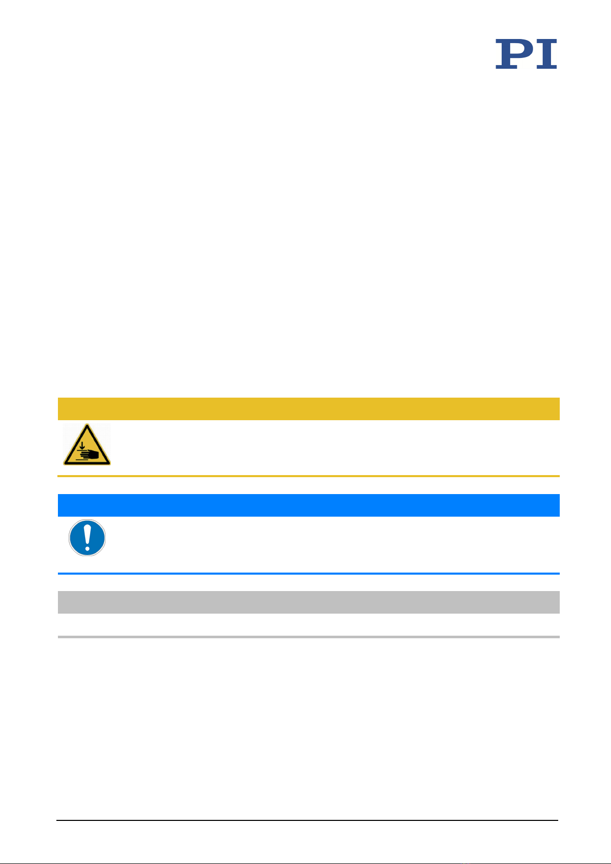
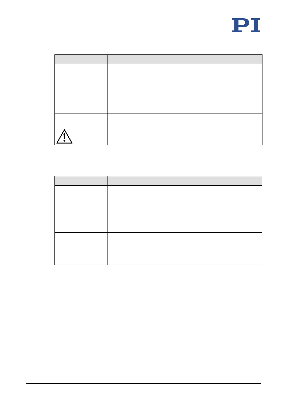
1.2 Symbols and Typographic Conventions...................................................................... 1
1.3 Definition of Terms..................................................................................................... 2
1.4 Figures ........................................................................................................................ 2
1.5 Other Applicable Documents ..................................................................................... 2
1.6 Downloading Manuals................................................................................................ 3
2Safety 5
2.1 Intended Use .............................................................................................................. 5
2.2 General Safety Instructions ........................................................................................ 5
2.3 Organizational Measures............................................................................................ 6
3Product Description 7
3.1 Model Overview ......................................................................................................... 7
3.2 Product View .............................................................................................................. 9
3.3 Product Labeling....................................................................................................... 10
3.4 Scope of Delivery...................................................................................................... 11
3.5 Optional Accessories ................................................................................................ 11
3.6 Suitable Controllers .................................................................................................. 12
3.7 Technical Features.................................................................................................... 12
3.7.1 Encoder........................................................................................................ 12
3.7.2 Limit Switches.............................................................................................. 12
3.7.3 Reference Switch......................................................................................... 14
3.7.4 Motor Brake................................................................................................. 14
3.7.5 Brushless Motor........................................................................................... 14
3.7.6 Integrated PWM Amplifier .......................................................................... 14
4Unpacking 15
5Installing 17
5.1 General Notes on Installing ...................................................................................... 17
5.2 Attaching the M-5x1 to an Underlying Surface........................................................ 18
5.2.1 Using a Surface with the Hole Pattern of the M-5x1 Base Body ................. 18
5.2.2 Using Adapters for the 25 mm × 25 mm Hole Pattern................................ 20
5.3 Fixing the Load to the M-5x1.................................................................................... 23
5.4 Building a Multi-Axis System .................................................................................... 24
5.4.1 General Notes on Building a Multi-Axis System .......................................... 25
5.4.2 Building an XY system.................................................................................. 26
5.4.3 Building a Z System with an Adapter Bracket.............................................. 28
5.5 Connecting the M-5x1 to a Controller...................................................................... 34
5.6 Connecting the Power Adapter to the M-5x1 .......................................................... 34
Contents

6Startup and Operation 37
6.1 General Notes on Startup......................................................................................... 37
6.2 Startup and Operation of the Positioner.................................................................. 39
6.2.1 M-5x1 Entries in the PI Positioner Database............................................... 39
7Maintenance 41
7.1 General Notes on Maintenance ............................................................................... 41
7.2 Performing Maintenance ......................................................................................... 41
7.3 Cleaning the M-5x1 .................................................................................................. 41
8Troubleshooting 43
8.1 General Notes on Troubleshooting .......................................................................... 43
8.2 Possible Causes and Correction................................................................................ 43
8.3 Moving the Platform by Hand .................................................................................. 45
9Customer Service 47
10 Technical Data 49
10.1 Specifications............................................................................................................ 49
10.1.1 Data Table.................................................................................................... 49
10.1.2 Maximum Ratings........................................................................................ 51
10.1.3 Ambient Conditions and Classifications ...................................................... 51
10.1.4 Limit Switch Specifications .......................................................................... 52
10.1.5 Reference Switch Specifications.................................................................. 52
10.2 Dimensions ............................................................................................................... 53
10.2.1 Positioner M-5x1 ......................................................................................... 53
10.2.2 Hole Pattern of the Motion Platform .......................................................... 54
10.2.3 M-592.10 Adapter Bracket .......................................................................... 55
10.2.4 M-500.206 Adapter Plate ............................................................................ 56
10.2.5 M-590.00 Three-Point Support, Two-Part................................................... 57
10.3 Pin Assignment ......................................................................................................... 59
10.3.1 D-sub 15 (m) Controller Connector ............................................................. 59
10.3.2 M8 (m) Power Adapter Connector.............................................................. 60
11 Old Equipment Disposal 61
12 European Declarations of Conformity 63

1 About this Document
M-5x1 High-Precision Linear Stage Version: 2.0.0 1
1.1 Objective and Target Group of this User Manual
This user manual contains the information needed for using the M-511, M-521, and M-531
(hereafter also referred to as called M-5x1) as intended.
Basic knowledge of closed-loop systems, motion control concepts, and applicable safety
measures is assumed.
The latest versions of the user manuals are available for download on our website.
1.2 Symbols and Typographic Conventions
The following symbols and typographic conventions are used in this user manual:
CAUTION
Dangerous situation
Failure to comply could lead to minor injury.
Precautions to avoid the risk.
NOTICE
Dangerous situation
If not avoided, the dangerous situation will result in damage to equipment.
Precautions to avoid the risk.
INFORMATION
Information for easier handling, tricks, tips, etc.
1
About this Document

1 About this Document
2 Version: 2.0.0 M-5x1 High-Precision Linear Stage
Symbol / Label Meaning
1.
2.
Action consisting of several steps with strict sequential order
Action consisting of one or more steps without relevant sequential
order
List item
p. 5 Cross-reference to page 5
RS-232 Label on the product indicating an operating element (example: RS-
232 interface socket)
Warning sign on the product which refers to detailed information in
this manual.
1.3 Definition of Terms
Term Explanation
Load Capacity Maximum load capacity in the vertical direction when the positioner is
mounted horizontally. The contact point of the load is at the center of
the motion platform.
Max. push/pull force Maximum force in the direction of motion. Some positioners may
apply higher forces, but this could limit their lifetimes. In the case of
vertical mounting, the specified value (p. 49) for models without a
gearhead and brake only applies when servo mode is switched on.
Incremental position
sensor
Sensor (encoder) for detecting changes of position or changes of
angle. Signals from the incremental position sensor are used for axis
position feedback. After the controller is switched on, referencing
must be done before absolute target positions can be commanded
and reached.
1.4 Figures
For better understandability, the colors, proportions, and degree of detail in illustrations can
deviate from the actual circumstances. Photographic illustrations may also differ and must not
be seen as guaranteed properties.
1.5 Other Applicable Documents
The devices and software tools from PI mentioned in this documentation are described in
separate manuals.

1 About this Document
M-5x1 High-Precision Linear Stage Version: 2.0.0 3
Product Document
C-863.12 DC Motor Controller MS249 User Manual
C-663.12 Stepper Motor Controller MS241 User Manual
C-884 DC Motor Controller MS243 User Manual
C-885 PIMotionMaster C885T0002 User Manual
C-863.12C885 for C-885 PIMotionMaster C863T0004 User Manual
C-863.20C885 for C-885 PIMotionMaster C863T0005 User Manual
The latest versions of the user manuals are available for download on our website.
1.6 Downloading Manuals
INFORMATION
If a manual is missing or problems occur with downloading:
Contact our customer service department (p. 47).
Downloading manuals
1. Open the website www.physikinstrumente.com/en/.
2. Search the website for the product number (e.g., F-511).
3. Click the corresponding product to open the product detail page.
4. Click the Downloads tab.
The manuals are shown under Documentation.
5. Click the desired manual and fill out the inquiry form.
The download link will then be sent to the email address entered.


2 Safety
M-5x1 High-Precision Linear Stage Version: 2.0.0 5
2.1 Intended Use
The M-5x1 is a laboratory device as defined by DIN EN 61010. It is intended for indoor use in an
environment which is free of dirt, oil, and lubricants.
According to its design, the M-5x1 is intended for positioning, adjusting, and shifting loads in
one axis at different velocities. The M-5x1 is not intended for applications in areas where failure
would be a considerable risk for people or the environment.
The M5x1 is intended for horizontal or vertical mounting. For the load limits with vertical
mounting, see "General Notes on Installation" (p. 17).
It is only possible to use the M-5x1 as intended when completely mounted and connected.
The M-5x1 must be operated with a suitable controller (p. 12). The controller is not included in
the scope of delivery of the M-5x1.
2.2 General Safety Instructions
The M-5x1 is built according to state-of-the-art technology and recognized safety standards.
Improper use can result in personal injury and/or damage to the M-5x1.
Use the M-5x1 for its intended purpose only, and when it is in perfect technical
condition.
Read the user manual.
Immediately eliminate any faults and malfunctions that may affect safety (p. 43).
The operator is responsible for installing and operating the M-5x1 correctly.
2
Safety

2 Safety
6 Version: 2.0.0 M-5x1 High-Precision Linear Stage
2.3 Organizational Measures
User manual
Always keep this user manual together with the M-5x1.
The latest versions of the user manuals are available for download on our website
(p. 2).
Add all information from the manufacturer such as supplements or technical notes to
the user manual.
If you give the M-5x1 to a third party, include this user manual as well as all other
relevant information provided by the manufacturer.
Only use the device on the basis of the complete user manual. Missing information due
to an incomplete user manual can result in damage to equipment.
Install and operate the M-5x1 only after you have read and understood this user
manual.
Personnel qualification
The M-5x1 may only be installed, started, operated, maintained, and cleaned by authorized and
appropriately qualified personnel.

3 Product Description
M-5x1 High-Precision Linear Stage Version: 2.0.0 7
3.1 Model Overview
Classification of the positioners
The stages of the M-511, M-521 and M-531 series are summarized under the designation M-5x1
in this manual.
All models are microtranslation stages with a ball screw. They differ with respect to:
Travel range
Drive type
Presence of a motor brake
Encoder type
M-5x1 Travel range in
mm
Travel range in
inches
x = 1 102 4
x = 2 204 8
x = 3 306 12
Version Drive type Brake
available
Encoder type
DC motor Linear Rotation
Direct
drive,
PWM
Direct
drive,
brushless,
PWM
Gearhead,
analog
Gearhead,
PWM
.DD1
.DD2
.PD1
.EC
.DG1
.PG1
3
Product Description

3 Product Description
8 Version: 2.0.0 M-5x1 High-Precision Linear Stage
Detailed model overview
Product number Product Description
M-511.DD1 Microtranslation stage, 102 mm, ActiveDrive DC motor, linear encoder
M-511.DD2 Microtranslation stage, 102 mm, ActiveDrive DC motor, linear encoder,
motor brake
M-511.DG1 Microtranslation stage, 102 mm, DC gear motor, rotary encoder
M-511.EC Microtranslation stage, 102 mm, brushless DC motor, rotary encoder
M-511.PD1 Microtranslation stage, 102 mm, ActiveDrive DC motor, rotary encoder
M-511.PG1 Microtranslation stage, 102 mm, ActiveDrive DC gear motor, rotary
encoder
M-521.DD1 Microtranslation stage, 204 mm, ActiveDrive DC motor, linear encoder
M-521.DD2 Microtranslation stage, 204 mm, ActiveDrive DC motor, linear encoder,
motor brake
M-521.DG1 Microtranslation stage, 204 mm, DC gear motor, rotary encoder
M-521.EC Microtranslation stage, 204 mm, brushless DC motor, rotary encoder
M-521.PD1 Microtranslation stage, 204 mm, ActiveDrive DC motor, rotary encoder
M-521.PG1 Microtranslation stage, 204 mm, ActiveDrive DC gear motor, rotary
encoder
M-531.DD1 Microtranslation stage, 306 mm, ActiveDrive DC motor, linear encoder
M-531.DD2 Microtranslation stage, 306 mm, ActiveDrive DC motor, linear encoder,
motor brake
M-531.DG1 Microtranslation stage, 306 mm, DC gear motor, rotary encoder
M-531.EC Microtranslation stage, 306 mm, brushless DC motor, rotary encoder
M-531.PD1 Microtranslation stage, 306 mm, ActiveDrive DC motor, rotary encoder
M-531.PG1 Microtranslation stage, 306 mm, ActiveDrive DC gear motor, rotary
encoder
Refer to the specifications for further technical data. (p. 49).

3 Product Description
M-5x1 High-Precision Linear Stage Version: 2.0.0 9
3.2 Product View
Figure 1: Positioner components (here: M-511)
1Base body
2Motor cover
3Spindle cover
4Motion platform
5Power adapter connector (M8 panel plug; not .DG1 models)
6Controller connector (D-sub 15 panel plug)

3 Product Description
10 Version: 2.0.0 M-5x1 High-Precision Linear Stage
3.3 Product Labeling
Figure 2: Product labeling
Position Labeling Description
1
"Risk of crushing" warning sign
2
Manufacturer's logo
2 WWW.PI.WS Manufacturer's address (website)
2 M-511.DD1 Product name (example), the characters following
the period refer to the model
2 SN: A16045786 Serial number (example), individual for each M-
5x1
Meaning of each position (from the left): 1 =
internal information, 2 and 3 = year of
manufacture, 4 to 9 = consecutive number
2 Country of Origin: Germany Country of origin
2
Warning sign "Pay attention to the manual!"
2
Old equipment disposal (p. 61)
2 CE conformity mark

3 Product Description
M-5x1 High-Precision Linear Stage Version: 2.0.0 11
3.4 Scope of Delivery
Product number Description
M-5x1.xxx Positioner according to the order (p. 7)
2504 Screw set for attaching the stage, load and mounting adapters
4 socket head screws, A2 M4×16 ISO 4762
4 socket head screws, A2 M4x30 ISO 4762
4 socket head screws, A2 M6×30 ISO 4762
Hex key AF 3 DIN 911
Hex key AF 5 DIN 911
MP119EK Short instructions for positioners with electric motors
For the models M-5x1.DD1, .DD2, .EC, .PG1, .PD1 additionally:
C-501.24050H Wide input range power supply 24 V DC / 50 W
3763 Power cord
K050B0003 Adapter for the power adapter connection; barrel connector to M8 4-pole
connector (f)
3.5 Optional Accessories
Product number Description
C-815.83 Motor cable, 10 m, D-sub, 15-pin/pole (m/f)
M-500.206 Adapter plate for mounting H-206 Hexapods on M-511, M-521 and M-531
stages. Material: Al
M-590.00 Three-point support for mounting M-505, M-510, M-511, M-521 and M-
531 stages on honeycomb tables etc. (metric and inches). Material: Al;
mass: 0.4 kg
Consisting of:
Adapter plate, wide (M59000001)
Adapter plate, narrow (M59000002)
M-592.10 Adapter bracket for mounting M-511, M-521, and M-531 stages vertically.
Material: Al; mass: 0.2 kg
To order, please contact our customer service department (p. 57).

3 Product Description
12 Version: 2.0.0 M-5x1 High-Precision Linear Stage
3.6 Suitable Controllers
Product number Description
C-863.12 Mercury servo controller, for DC motors and PWM motor drivers
C-863.20C885 Motion controller module for DC motors, for C-885 PIMotionMaster
C-884 Controller for DC motors
PC software is included in the scope of delivery of the controllers from PI. The operation of the
controllers is described in the corresponding user manuals.
3.7 Technical Features
3.7.1 Encoder
Linear encoder
The M-5x1.DD1 and .DD2 models are equipped with an optical linear encoder. This measures
the actual position directly (direct metrology). Errors in the drive, such as nonlinearity, backlash
or elastic deformations cannot influence measuring of the position.
For the encoder resolution, refer to the table in the "Specifications" section (p. 49).
Rotary encoder
The M-5x1.PD1, .PG1, .DG1, and .EC models are equipped with an incremental rotary encoder.
A rotary encoder, also called an incremental rotary encoder, is implemented at a rotating point
in the drivetrain, e.g., the motor shaft.
3.7.2 Limit Switches
The positioner is equipped with noncontact, magnetic (Hall effect) limit switches.
Each limit switch sends its signal to the controller on a dedicated line. If reached, the controller
stops the motion. If the controller does not stop the motion in time, the positioner runs into the
hard stop.
For further information, refer to "Limit Switch Specifications" (p. 51).
Limit switch* Availability of the signal Function
"Inner" limit
switches N1 and
P1
Output to the controller
on the D-sub 15 panel
plug (p. 54)
Also refer to the "Limit
Switch Specifications"
(p.49).
When triggering takes place, the controller
switches off the servo mode for the affected
axis and thereby stops the motion.
The motion platform can be moved away from
the limit switch by command, see
"Troubleshooting" (p. 43).
"Outer" limit
switches N2 and
No connection to the
controller
The triggering interrupts the power supply to
the drive via a relay. The motion platform

3 Product Description
M-5x1 High-Precision Linear Stage Version: 2.0.0 13
Limit switch* Availability of the signal Function
P2
cannot be moved away from the limit switch by
command but must be moved manually (p. 45).
*N = negative limit switch, P = positive limit switch
Figure 3: Limit switch arrangement with M-5x1
The gap between N1 and N2 or P1 and P2 is approx. 5.3 mm in each case.
INFORMATION
In the case of controllers from PI, the permissible travel range of the positioner is represented
via parameters in the controller. Suitable parameter values can be loaded from a positioner
database in the supplied PC software; see also "M-5x1 Entries in the PI Positioner Database" (p.
39). With the values loaded from the positioner database for the lower and upper limit of the
travel range, the limit switches cannot be approached with motion commands. The controller
furthermore calculates the dynamics profile during motion so that the positioner decelerates in
time before the end of the permissible travel range. The positioner can only reach the limit
switch in exceptional cases, e.g., with a very high velocity and/or under high load.
Refer to the user manual for the controller for details.

3 Product Description
14 Version: 2.0.0 M-5x1 High-Precision Linear Stage
3.7.3 Reference Switch
The positioner is equipped with a direction-sensing reference switch, which is located at about
the midpoint of the travel range (see "Reference Switch Specifications" (p. 52)).
The commands that use the reference signal are described in the user manual for the controller
and/or in the corresponding software manuals.
3.7.4 Motor Brake
The M-5x1.DD2 models are equipped with a motor brake. Positioners with a motor brake are
especially suited for vertical mounting.
The motor brake is activated and deactivated via the connected controller. Controllers from PI
activate the brake automatically when servo mode is switched off. Refer to the user manual for
the controller for details.
3.7.5 Brushless Motor
The M-5x1.EC models are equipped with a brushless DC motor. The motor is electronically
commuted and therefore very low wear.
3.7.6 Integrated PWM Amplifier
The M-5x1.DD1, .DD2, .PD1 und .EC models with direct drive are equipped with a PWM
amplifier ("ActiveDrive concept"). The motor and PWM amplifier are installed in a joint housing
and therefore optimally integrated and shielded. The PWM amplifier only receives the control
signals from the controller, whereas the supply voltage is provided via an external power
adapter. The ActiveDrive concept allows high motor power and dynamics at low power loss.
The M-5x1.PG1 models with DC gear motor are only equipped with a PWM amplifier for
compatibility reasons.

4 Unpacking
M-5x1 High-Precision Linear Stage Version: 2.0.0 15
1. Unpack the M-5x1 with care.
2. Compare the contents with the scope of delivery according to the contract and the
delivery note.
3. Inspect the contents for signs of damage. If any parts are damaged or missing, contact
our customer service department immediately.
4. Keep all packaging materials in case the product needs to be returned.
4
Unpacking

Table of contents
Other PI Laboratory Equipment manuals

PI
PI N-331 User manual

PI
PI L-412.039232B User manual

PI
PI U-624 User manual

PI
PI H-850 Series User manual

PI
PI L-417.XX9232B Series User manual

PI
PI A-121 Series User manual

PI
PI Pimag V-417.216211E1 User manual

PI
PI V-417.136211E1 PIMAG User manual

PI
PI Q-521 User manual

PI
PI Q-Motion Q-545 Series User manual
Popular Laboratory Equipment manuals by other brands

Intellinet
Intellinet 524179 reference guide

Sonel
Sonel KT-385 user manual

Energenics
Energenics UV-MAX Installation & operation manual

Velp Scientifica
Velp Scientifica RC F20700431 instruction manual

ANTAIRA
ANTAIRA INJ-0200G-at-24 Series Quick installation guide

Thermo Scientific
Thermo Scientific 5030i SHARP instruction manual