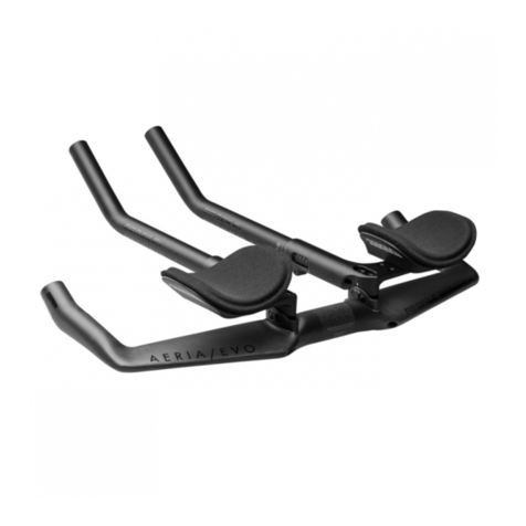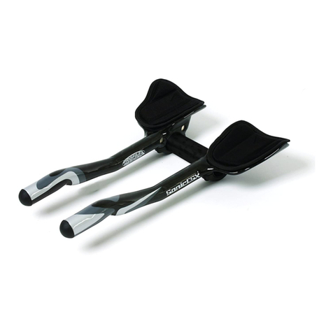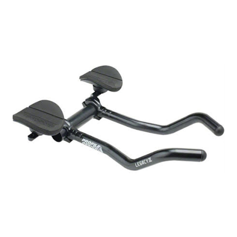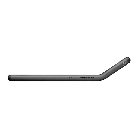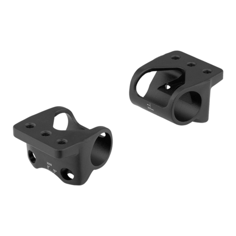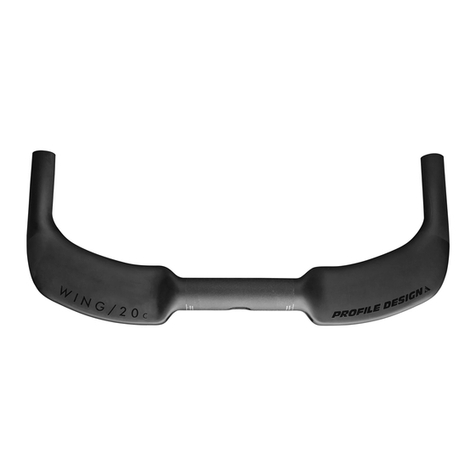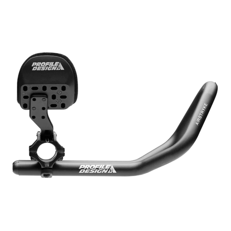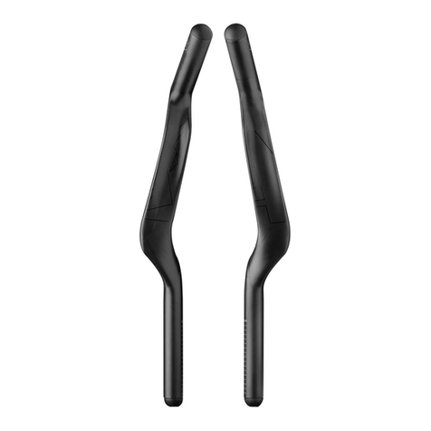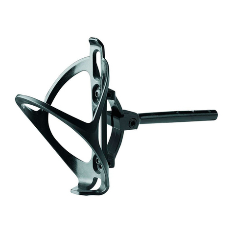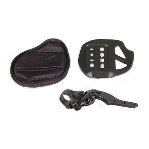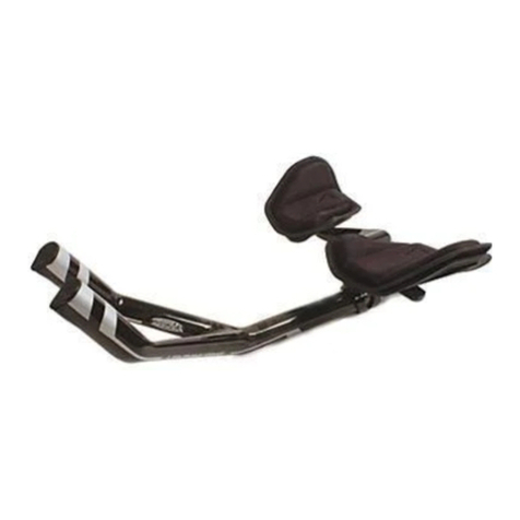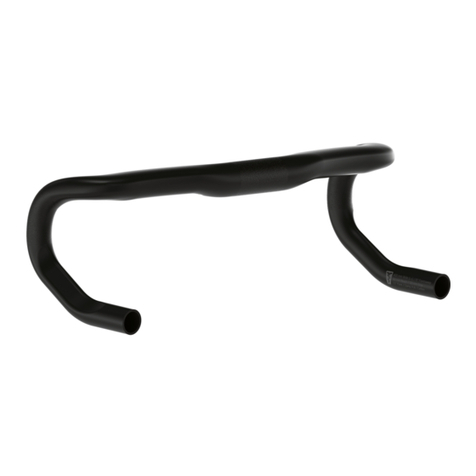
Wing20C+ Aerobar
98
INSTALLATION INSTRUCTIONS
1. Determine whether you wish to install the bar in the up or down orientation.
2. We recommend routing the cables through the bar prior to assembly.
3. If using electronic shifting. (diagram on page 13)
a. Route the electronic cables through the basebar to the brake levers using a guide cable.
b. Route the electronic cables for the aerobars through the basebar and out of the bracket
mount on the top of the basebar.
c. If the junction box is to be hidden inside the stem (Shimano only) route all the electronic
cables out of the central hole and connect to the junction.
d. Once the electronic cables have been routed, carefully route the brake cables, ensuring that
you don’t pinch the electronic cables and have the correct brake setup for the bar orientation.
e. The brake cables can exit either through the central clamp hole or the holes at the rear of the
wing.
4. If using mechanical shifting. (diagram on page 11)
a. Route the brake cables through the basebar, using either the central clamp hole or the exit
holes at the rear of the wing.
5. Apply a thin coating of grease to the curved lower surface of the aerobar bracket.
6. If using risers (available separately) consult the bolt length table to ensure you use the correct
length bolt for your setup. Apply grease to the contact surfaces of the risers.
a. Note that the risers are directional, the flattened end faces to the rear of the bar.
7. Assemble the bracket and risers.
a. If using electronic shifting, route the cables up through the risers and bracket prior to
installing bolts.
b. The electronic cable can exit the top of the risers to the rear, or be routed over the barrel (prior
to installation of the barrel).
c. Assembly tip – it is usually easier to start with the bolt at the front of the bracket.
d. Use the locator groove on the side of the threaded barrel (in the aerobar bracket) to aid in
aligning the barrel for bolt installation.
8. Tighten the bolts until the aerobar bracket is firmly in place at the desired angle (0-15deg) and
repeat with the other side.
9. Apply assembly compound to the inside surfaces of the extension clamp.
10. Install the extensions in the desired position and tighten the M3 extension fixing bolt using the
4mm Hex wrench so they are held snugly.
11. Install the shifters as per the shifter manufacturer’s instructions. We recommend a light
coating of assembly compound on the inside of the extension prior to installing the shifter.
12. Install the cables as per instructions from the shifter manufacturer.
13. Check the placement of the brackets and extensions then use the torque wrench with a 5mm
fitting to tighten the aerobar bracket clamp to 6Nm.
14. Then use the torque wrench with a 4mm fitting to tighten the extension clamp to 5Nm.
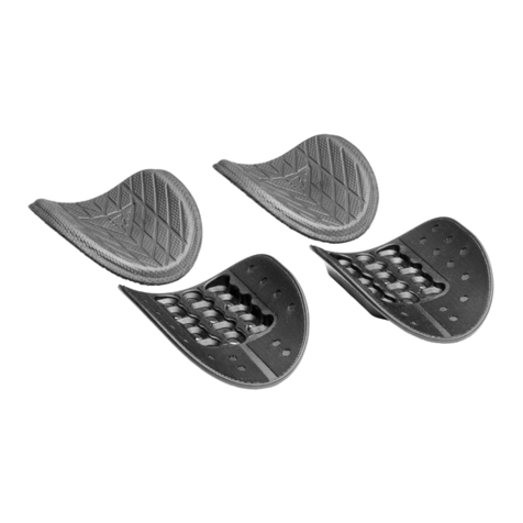
15. Apply a light coating of grease to the surface of the armrest mounting area.
16. Fasten the armrests to the brackets using the M6x12mm countersunk bolts, note that the
armrests have an offset design so care is required to ensure each side is positioned in the
same way.
17. Apply a light coating of grease to the top surface of the bolts as a protective layer against the
effects of sweat.
WARNING:
Using bolts that are too long for the risers and bracket will prevent correct installation.
Bolts that are too short may lead to failure during use.
