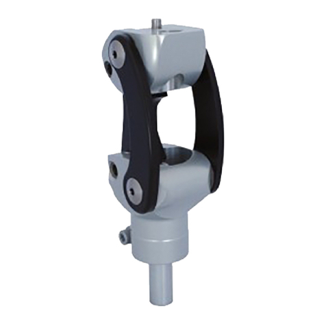
PROTEOR MATIK 1P200 User manual

MATIK
1P200 / 1P200-KD
FR Notice d’Utilisation
EN Instruction for use
DE Gebrauchsanweisung
IT Istruzioni per l’uso
ES Instrucciones de uso
T Instruções de utilização
NL Gebruikershandleiding
DA Brugervejledning
NO Brukerveiledning
SV Bruksanvisning
FI Käyttöohjeet
L Instrukcja użytkowania
CS Návod k použití
SK Návod na používanie
HR Upute za uporabu
RU Инструкция по использованию
UK Інструкція з використання
JA 取扱説明書
ZH 使用说明
1
2
0
0
99
-
0421

Transmettre au Patient les consignes (§ 3, 7, 8, 9)
1. ELEMENTS NCLUS
Désignation Référence nclus / Vendu séparément
Genou 1P200(-KD) Inclus
Esthétique monobloc 1G18 Vendu sép rément
2. DESCR PT ON, PROPR ETES ET MECAN SME D’ACT ON
A. Description
Genou pneum tique à 4 xes qui existe en deux versions différentes :
•1P200 : Li ison supérieure vec pyr mide mâle, d ptée ux mput tions tr nsfémor les ou
dés rticul tions de h nche.
•1P200-KD : Li ison supérieure vec filet ge (M36×1.5), d ptée ux mput tions longues ou
dés rticul tions de genou.
D ns les 2 versions, l connexion inférieure se f it vec connecteur pyr mid l mâle.
B. Propriétés
Référence 1P200 1P200-KD
Poids 743 g
Flexion maximale 170°
Poids maximum Patient
(Port de charge inclus) 125 kg
Ce dispositif été testé suiv nt l norme NF EN ISO 10328 pour un nive u de ch rge P6 (soit 125Kg), pend nt 3 millions de cycles,
correspond nt à une durée de vie de 4 à 5 ns suiv nt l’ ctivité du p tient.
C. Mécanisme d’action
En extension, le système d’ rticul tion à biellettes positionne le centre inst nt né de rot tion derrière l ligne de ch rge, confér nt
insi u genou une bonne st bilité en ph se d’ ppui. Ch que vitesse de flexion et d’extension est régl ble de m nière indépend nte.
Le r ppel en extension n’est p s régl ble.
MAT K – 1P200(-KD)
Notice d’utilisation Orthoprothésiste
Lire avant toute utilisation
1P20099
2021-04
2
0
1
2
Axe théorique de rotation
Hauteur de construction = 175 mm
Hauteur de construction = 171,5 mm
8 mm
=
Hauteur totale
=
1P200
204 mm
1P200-KD
195 mm
11,5mm

NOTICE D’UTILISATION P ge 2 sur 5
3. DEST NAT ON/ ND CAT ONS
Ce dispositif médic l est fourni ux professionnels de s nté (orthoprothésiste) qui formeront le p tient à son utilis tion. L prescription est
f ite p r un médecin vec l’orthoprothésiste, qui jugent de l’ ptitude du p tient à l’utiliser.
Ce dispositif est à us ge sur PATIENT UNIQUE. Il ne doit p s être réutilisé sur un utre p tient.
Ce dispositif est uniquement destiné à l’ pp reill ge prothétique d’une personne mputée tr nsfémor le
(ou dés rticulée de h nche) ou dés rticulée du genou. Il est préconisé spécifiquement pour des p tients
ctifs ou peu ctifs (L2/L3) permett nt des ctivités quotidiennes.
Poids m ximum (port de ch rge inclus) : 125 kg
Non adapté pour les enfants.
L flexion m ximum du genou est de 170°. Elle peut cepend nt être limitée p r le volume de l’emboîture ou p r le revêtement
esthétique.
4. BENEF CES CL N QUES
Le dispositif ssure :
•Les dépl cements de l vie de tous les jours vec un minimum de m inten nce
•Un poids et encombrement réduits.
•Une flexion jusqu’à 170° pour s’ sseoir ou se mettre à genou.
•Un esp ce entre le pied et le sol en ph se pendul ire élevé, évit nt le cont ct du pied sur le sol lors de l ph se pendul ire.
•L st bilité et sécurité en ph se d’ ppui grâce à l géométrie rticul ire 4 xes.
5. ACCESSO RES ET COMPAT B L TES
Référence 1P200 1P200-KD
Li ison supérieure
Ancre
1K179+1K183
1K173 ou 1K176
1K177 (poids m xi 100Kg)
1K179
Connecteurs 1K172 ou 1K207-HD 1K184
Li ison inférieure Tube et
connecteur
1D41-HD et 1G01-HD
1D52-P6
6. MONTAGE ET M SE EN PLACE SUR LE PAT ENT
A. Alignements
Alignements statiques :
D ns un pl n s gitt l, l ligne de ch rge p sse p r le gr nd Troch nter, entre 0 et 10 mm en v nt de l’ xe du genou.
Au nive u du pied, respecter les consignes d’ lignement du f bric nt.
D ns un pl n front l, l ligne de ch rge p sse p r le milieu de l’emboîture, le milieu du genou et entre le premier et le second
orteil du pied.

NOTICE D’UTILISATION P ge 3 sur 5
Alignements dynamiques :
1- Pour ugmenter l st bilité, incliner le genou comme
ceci (pour dépl cer le centre inst nt né de rot tion vers
l’ rrière) en giss nt sur les connecteurs supérieur et
inférieur.
Pour l diminuer, procéder inversement.
2- Repositionner ensuite le pied, suiv nt l’ lignement
préconisé, en giss nt sur les connecteurs intermédi ires.
L connexion p r filet ge M36×1.5 de l version KD ne permet p s de modific tion de l’ lignement. L’emboiture doit donc être ré lisée
en conséquence.
Vérifier l’ lignement à l’ ide d’un outil pproprié (l ser, fil à plomb, …)
≈1/3 ≈2/3
H talon
Ligne de charge
Grand Trochanter
Alignement du pied :
Voir la notice du pied
La ligne de charge passe entre 0 et 10 mm
(0 recommandé) devant l’axe avant
supérieur (axe de rotation théorique du
genou).
+
-
St bilité St bilité

NOTICE D’UTILISATION P ge 4 sur 5
B. Réglage de la cadence de marche
Le genou est livré réglé pour une c dence de m rche moyenne.
Pour l sécurité de son p tient, l’orthoprothésiste doit effectuer les premiers ess is vec les régl ges usine entre des b rres
p r llèles.
Le modèle de pied utilisé peut influencer les régl ges du genou. Il convient de régler le genou à ch que ch ngement de pied.
S’ ssurer de l sécurité du p tient en toute circonst nce et plus p rticulièrement lors des descentes de pentes ou d’esc lier.
Après ch que intervention de m inten nce, un nouve u régl ge de genou est nécess ire.
Pour d pter ces régl ges à l c dence de m rche du p tient, gir sur les
pointe ux E et F à l’ ide de l clé six p ns.
Il est conseillé d’effectuer les régl ges d ns l’ordre suiv nt :
1. Réglage de la Flexion (F)
Agir sur le pointe u F : Visser le pointe u pour diminuer l’ ngle de
flexion, à contr rio dévisser le pointe u pour l’ ugmenter.
2. Réglage de l’Extension (E)
Agir sur le pointe u E : Visser pour diminuer l’imp ct en fin
d’extension.
Lorsque ces régl ges sont ré lisés, s’ ssurer du retour en extension complète du
genou à f ible vitesse de m rche pour prévenir tout risque de chute du p tient.
C. Finitions
Il est préconisé de renforcer l’esthétique dev nt l’ rticul tion pour prolonger s durée
de vie.
Butée en flexion maximum :
Lorsque le p tient est ccroupi ou genouillé, l’emboîture doit venir u cont ct du
boss ge de l’ xe inférieur de l bielle rrière. Elle ne doit p s toucher l bielle rrière, ni
l pl tine sous peine de destruction du genou.
L’esthétique peut modifier les régl ges initi ux du genou et limiter cert ins
mouvements. Il convient de toujours vérifier le fonctionnement du genou une fois
l’esthétique montée.
7. DETECT ON DES DYSFONCT ONNEMENTS
Si vous const tez un comportement norm l ou que vous sentez des modific tions des c r ctéristiques du dispositif, ou si celui-ci reçu
un choc import nt, consultez votre orthoprothésiste.
8. M SES EN GARDE, CONTRE- ND CAT ONS, EFFETS SECONDA RES
A. Mises en garde
Attention, une ph se d’ pprentiss ge peut être nécess ire pour p sser d’un genou à l’ utre.
Pour éviter les risques de chute lors de l descente d’esc lier, il est recomm ndé de se tenir à l r mpe.
Afin de ne p s détériorer le genou, ne p s utiliser de t lc pour éliminer des bruits de frottement, m is plutôt un spr y siliconé. Le
t lc dégr de les éléments méc niques, ce qui peut entr iner un dysfonctionnement vec un risque de chute pour le p tient.
PROTEOR se dégage de toute responsabilité en cas d’utilisation de talc.
Un risque de coincement de doigt ou de pincement des vêtements d ns l’ rticul tion du genou existe. Pour éviter tout risque de
blessure du f it du mouvement de l’ rticul tion, bien veiller à ce que personne ne mette les doigts à proximité ou à l’intérieur du
méc nisme.
Le genou résiste aux intempéries, mais nécessite d’être immédiatement séché après avoir été mouillé. L pénétr tion d’e u d ns
le méc nisme pneum tique peut générer l détérior tion du ressort de r ppel en extension et donc détruire le genou. Il doit être
protégé de l pénétr tion d’e u.
B. Contre-indications
Il est formellement proscrit de démonter les c pots, de visser ou dévisser une quelconque vis de ce genou à l’exception des deux
vis de régl ge E et F.
Ne j m is gr isser les xes du genou, cel pourr it entr iner leur détérior tion r pide.
Bossage de
l’axe arrière :
Zone de contact
avec l’emboiture.
Bielles
Platine

NOTICE D’UTILISATION P ge 5 sur 5
Le genou est prévu pour un poids m ximum de 125kg (port de ch rge inclus).
L g r ntie ne couvre p s les détérior tions consécutives à un m uv is us ge, à un lignement in d pté, à une utilis tion d ns un
environnement très poussiéreux et s ns protection d ptée, ou toute utilis tion in ppropriée.
Il ne f ut p s exposer le genou d ns des environnements pouv nt provoquer l corrosion des pièces mét lliques (e u douce, e u
de mer, e u chlorée, cides, etc..).
l est interdit de se doucher ou de se baigner avec la prothèse, cel risquer it de dégr der s résist nce et son bon
fonctionnement.
Ne j m is l isser ce dispositif près d’une source de ch leur : risque de brûlure et de dég gement toxique.
L’utilis tion de solv nts est proscrite.
C. Effets secondaires
Il n’y p s d’effets second ires directement lié u dispositif.
Tout incident gr ve survenu en lien vec le dispositif doit f ire l’objet d’une notific tion u f bric nt et à l’ utorité compétente de
l’Et t membre.
9. ENTRET EN, STOCKAGE, EL M NAT ON ET DUREE DE V E
A. Entretien/ nettoyage
Vous pouvez nettoyer le genou à l’ ide d’une éponge humide
Ne p s l’immerger ou le p sser sous l’e u
Après une intempérie ou une spersion involont ire, sécher immédi tement votre genou.
Les butées peuvent nécessiter un rempl cement :
•Butée de rech nge : EE014 (2 sont nécess ires)
B. Stockage
Tempér ture d’utilis tion et de stock ge : -10°C à +40°C
Humidité rel tive de l’ ir : ucune restriction
C. Elimination
Les différents éléments de ce dispositif sont des déchets spéci ux : él stomère, m tière pl stique, luminium, tit ne, cier et l iton.
Ils doivent être tr ités selon l législ tion en vigueur.
D. Durée de vie
Il est conseillé de f ire effectuer un contrôle nnuel p r un orthoprothésiste.
10. DESCR PT ON DES SYMBOLES
Fabricant
Risque identifié Marquage CE et année de 1ère déclaration
11. NFORMAT ONS REGLEMENTA RES
Ce produit est un dispositif médic l m rqué CE et certifié conforme u règlement (UE) 2017/745
12. NOM ET ADRESSE DU FABR CANT
PROTEOR SAS
6 rue de l Redoute – 21850 S int-Apollin ire – Fr nce
Tel : +33 3 80 78 42 42 – F x : +33 3 80 78 42 15
[email protected] – www.proteor.com

Pass on § 3, 7, 8 and 9 of these instructions to the Patient
1. COMPONENTS INC UDED
Designation Ref. Included/Sold separately
Knee 1P200(-KD) Included
One-part cosmetic cover 1G18 Sold separately
2. DESCRIPTION, PROPERTIES AND MECHANISM OF ACTION
A. Description
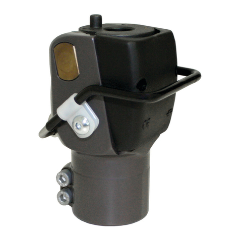
4-axis pneumatic knee available in two different versions:
•1P200: Male pyramid proximal adapter, suitable for patients who have had a transfemoral
amputation or hip disarticulation.
•1P200-KD: Threaded proximal adapter (M36×1.5), suitable for patients with a long
amputation stump or who have had a knee disarticulation.
For both versions, the distal connection is made via a male pyramid connector.
B. Properties
Ref. 1P200 1P200-KD
Weight 743 g
Maximum flexion 170°
Maximum patient weight
(Including carried load) 125 kg
This device has undergone a three-million-cycle test, in accordance with standard NF EN ISO 10328 at a P6 load level (i.e. 125 kg),
which corresponds to a service life of 4 to 5 years, depending on the patient’s mobility level.
C. Mechanism of action
When in extension, the system of linkages ensures that the instantaneous centre of rotation is to the rear of the load line, which keeps
the knee stable during the stance phase. The speed of every flexion and extension movement can be adjusted independently.
The extension assist is not adjustable.
MATIK – 1P200(-KD)
Instructions for use for Prosthetists/Orthotists
Please read before using or working on the device
1P20099
2021-04
2
0
1
2
Theoretical axis of rotation
Build height = 175 mm
Build height = 171.5 mm
8 mm
= Total height =
1P200
204 mm
1P200-KD
195 mm
11.5 mm

INSTRUCTIONS FOR USE Page 2 of 5
3. INTENDED USERS/INDICATIONS
This medical device is supplied to healthcare professionals (prosthetists/orthotists) who then instruct the patient in how to use it. The
prescription is drawn up by a doctor. The doctor works with a prosthetist/orthotist to assess whether the patient is suited to using the device.
This device should be used on ONE P TIENT ONLY. It must not be reused on other patients.
This device is exclusively intended to be used as prosthetic equipment for patients who have undergone
transfemoral amputation, hip disarticulation or knee disarticulation. It is specifically recommended for
active or slightly active patients (L2/L3) and allows them to perform everyday activities.
Maximum weight (including carried load): 125 kg
Not suitable for children.
The maximum knee flexion is 170°. This flexion may, however, be limited by the volume of the socket or by the cosmetic covering.
4. C INICA BENEFITS
The device allows:
•Everyday mobility with minimum maintenance
•The patient to choose a lighter and smaller knee.
•Flexion of up to 170° for sitting or kneeling.
•Good clearance between the foot and the ground in the swing phase, to avoid contact.
•High levels of stability and safety in the stance phase thanks to the 4-axis joint geometry.
5. ACCESSORIES AND COMPATIBI ITIES
Ref. 1P200 1P200-KD
Proximal adapter
nchor
1K179+ 1K183
1K173 or 1K176
1K177 (max. weight 100 kg)
1K179
Connectors 1K172 or 1K207-HD 1K184
Distal adapter Tube and
connector
1D41-HD and 1G01-HD
1D52-P6
6. ASSEMB Y AND FITTING TO THE PATIENT
A. Aligning
Static alignment:
In the sagittal plane, the load line passes through the greater trochanter and between 0 and 10 mm in front of the axis of the
knee.
lign the foot in compliance with the manufacturer’s instructions.
In the frontal plane, the load line passes through the middle of the socket, through the middle of the knee and between the
first and second toes.

INSTRUCTIONS FOR USE Page 3 of 5
Dynamic alignment:
1- To increase the stability, incline the knee as indicated
(to move the instantaneous centre of rotation to the rear)
by adjusting the proximal and distal connectors.
To reduce the stability, incline the knee in the opposite
direction.
2- Then reposition the foot, in accordance with the
recommended alignment, by adjusting the connectors
between the knee and the foot.
The threaded M36×1.5 adapter for the KD version does not accommodate any alignment adjustment. The socket must therefore be
made accordingly.
Check the alignment using suitable equipment (line laser, plumb line, etc.)
≈1/3
≈2/3
Heel H
Load line
Greater trochanter
Aligning the foot:
Refer to the instructions for the
foot
The load line passes between 0 and 10 mm
(0 is recommended) in front of the knee
joint axis (the theoretical axis of rotation of
the knee).
+
-
Stability Stability

INSTRUCTIONS FOR USE Page 4 of 5
B. Adjusting the walking pace
On delivery, the knee is set up for walking at medium pace.
For patient safety reasons, the prosthetist/orthotist must begin the adjustment process with the knee set to its factory settings and
with the patient walking between parallel bars.
The model of foot used may have an effect on the adjustment of the knee. The knee should be readjusted whenever the foot is changed.
Prioritise patient safety in all circumstances, particularly to ensure that slopes and stairs can be negotiated safely.
fter performing any maintenance the knee must be readjusted.
To adapt the knee to the patient’s pace of walking, adjust hex set screws E and F
using an llen (hex) key.
It is advisable to perform these adjustments in the following order:
1. Adjusting the Flexion (F)
Turn hex set screw F: Screw in the set screw to reduce the angle of
flexion, and unscrew to increase it.
2. Adjusting the Extension (E)
Turn hex set screw E: Screw in to increase the cushioning of the
impact when the knee reaches full extension.
Once these adjustments have been made, ensure that the knee returns to full
extension when walking slowly to ensure that there is no risk of the patient falling.
C. Finishing
It is advisable to reinforce the cosmetic cover in front of the joint to prolong its service
life.
Maximum flexion stop:
When the patient is crouching or kneeling, the socket must come into contact with the
rear flexion limit on the rear linkage. It must not touch the rear linkage, or the plate,
since this might damage or destroy the knee.
The cosmetic cover may modify the initial knee settings and limit certain movements. It
is advisable to always check the operation of the knee, once the cosmetic cover has
been fitted.
7. DETECTING ANY MA FUNCTIONING
If you notice that the device is behaving abnormally or if its characteristics feel different, or if it has been badly knocked, consult your
prosthetist/orthotist.
8. WARNINGS, CONTRAINDICATIONS, SIDE EFFECTS
A. Warnings
Caution, the patient may need to take time to get used to a new knee.
To reduce the risk of falling when going down stairs, it is advisable to hold on to handrail.
So as not to damage the knee, do not apply talcum powder to eliminate rubbing noises - use silicon spray instead. Talc degrades
the mechanical components, which might cause a malfunction and possibly a fall.
PROTEOR disclaims all liability if talcum powder is used.
It is possible to trap a finger or pinch clothing in the knee joint. To avoid the any injury caused by the movement of the joint, make
sure that no-one’s hand or fingers is near the mechanism.
The knee is resistant to bad weather, but needs to be dried immediately if it does get wet. ny water that gets into the pneumatic
mechanism may lead to the deterioration of the extension assist spring and thus the destruction of the knee. It must, therefore, be
protected against any ingress of water
B. Contraindications
The following are strictly prohibited: removing the covers, screwing in or unscrewing any screws on the knee with the exception of
the two adjustment screws E and F.
Never lubricate the knee pins; this can cause them to degrade rapidly.
Rear flexion
limit: Contact
area with the
socket.
Linkages
Upper
plate
INSTRUCTIONS FOR USE Page 5 of 5
The knee has been designed for patients with a maximum weight of 125 kg (including carried load).
The warranty does not cover damage or degradation caused by misuse, unsuitable alignment, use without suitable protection in
a very dusty environment or any other inappropriate use.
The knee must not be exposed to environments which might induce corrosion of the metal components (fresh water, sea water,
chlorinated water, acids, etc.).
Showering or taking a bath while wearing the prosthesis is prohibited; this might impair its properties and its correct operation.
Never leave this device near a source of heat since it might burn or release toxic fumes.
The use of solvents is prohibited.
C. Side effects
There are no side effects directly associated with the device.
ny serious incident that occurs which relates to the device must be reported to the manufacturer and to the competent authority of
the member state in which the incident occurred.
9. MAINTENANCE, STORAGE, DISPOSA AND SERVICE IFE
A. Maintenance/cleaning
You can clean the knee using a damp sponge
Do not immerse the knee or hold it under running water
Dry you knee immediately if it is exposed to bad weather or accidental splashing.
The stops may need to be replaced:
•Spare stop: EE014 (2 are required)
B. Storage
Service and storage temperature: -10°C to +40°C
Relative humidity of the air: no restrictions
C. Disposal
The various components of this device are considered as special waste: elastomer, plastic, aluminium, titanium, steel and brass. They
must be treated in accordance with current, applicable legislation.
D. Service life
It is advisable to arrange for a prosthetist/orthotist to check the product once a year.
10. DESCRIPTION OF THE SYMBO S
Manufacturer
Identified risk
CE marking and year of first declaration of
conformity
11. REGU ATORY INFORMATION
This product is a CE-marked medical device that is certified as conforming with regulation (EU) 2017/745
12. NAME AND ADDRESS OF MANUFACTURER
PROTEOR S S
6 rue de la Redoute – 21850 Saint- pollinaire – France
Tel.: +33 3 80 78 42 42 – Fax: +33 3 80 78 42 15
[email protected] – www.proteor.com

An den Patienten zu übermittelnde Anweisungen (Punkte 3, 7, 8 und 9)
1. LI F RUMFANG
Bezeichnung Best.-Nr. nthalten/Separat erhältlich
Prothesenkniegelenk 1P200(-KD) Enthalten
Monoblock-Optik 1G18 Separat erh ltlich
2. B SCHR IBUNG, IG NSCHAFT N UND WIRKUNGSM CHANISMUS
A. Beschreibung
Pneumatisches Vier-Achs-Prothesenkniegelenk erh ltlich in zwei unterschiedlichen
Ausführungen:
•1P200: Obere Verbindung mit Pyramidenadapter geeignet für oberschenkelamputierte
Patienten oder als Hüftexartikulationsprothese.
•1P200-KD: Obere Verbindung mit Gewinde (M36x1.5) geeignet für lange Stümpfe oder
Hüftexartikulationen.
Die untere Verbindung beider Ausführungen geschieht über einen Pyramidenadapter.
B. igenschaften
Best.-Nr. 1P200 1P200-KD
Gewicht 743 g
Maximale Beugung 170 °
Maximales
Anwendergewicht
(einschl. Belastung)
125 kg
Dieses Medizinprodukt wurde gem ß der Norm DIN EN ISO 10328 auf den Belastungsgrad P6 (125 kg) nach drei Millionen Zyklen
geprüft, was einer Lebensdauer von 4 bis 5 Jahren je nach T tigkeit des Patienten entspricht.
C. Wirkungsmechanismus
Im ausgestreckten Zustand positioniert das Gelenksystem mit Schwenkarmen den Momentdrehpunkt hinter der Lotlinie, um dem
Prothesenkniegelenk somit in der Standbeinphase ausreichend Stabilit t zu verleihen. Die einzelnen Geschwindigkeiten der Beugung
und Streckung können unabh ngig eingestellt werden.
Der Vorbringer kann nicht eingestellt werden.
MATIK – 1P200(-KD)
Gebrauchsanweisung für Orthopädietechniker
Vor Gebrauch aufmerksam lesen
1P20099
2021/04
2
0
1
2
Theoretische Drehachse
Aufbauhöhe = 175
mm
Aufbauhöhe = 171,5
mm
8 mm
= Gesamthöhe =
1P200
204 mm
1P200-KD
195 mm
11,5 mm

GEBRAUCHSANWEISUNG Seite 2 von 5
3. ZW CKMÄßIG R G BRAUCH/INDIKATION N
Dieses Medizinprodukt richtet sich an medizinische Fachkr fte (Orthop dietechniker), die den Patienten in die Anwendung einweisen. Die
Verschreibung wird von einem Arzt nach Absprache mit dem Orthop dietechniker ausgestellt, sofern sie den Patienten für f hig halten,
diese Prothese zweckm ßig zu verwenden.
Dieses Medizinprodukt richtet sich an EINEN EINZIGEN PATIENTEN. Es darf keinesfalls von einem anderen Patienten wiederverwendet
werden.
Dieses Medizinprodukt wurde für die orthop dische Behandlung bei oberschenkelamputierten Patienten
(oder als Hüft- bzw. Knieexartikulationsprothese) entwickelt. Die Prothese wird speziell für aktive sowie
weniger aktive Patienten (L2/L3) empfohlen, um t glichen Aktivit ten auszuführen.
Maximales Anwendergewicht (einschl. Belastung): 125 kg
Nicht für Kinder geeignet.
Der maximale Beugewinkel des Prothesenkniegelenks betr gt 170 °. Er kann jedoch durch das Schaftvolumen bzw. die Schaumkosmetik
eingeschr nkt werden.
4. KLINISCH VORT IL
Das Medizinprodukt sorgt für:
•Problemlose allt gliche Bewegungen bei minimaler Wartung.
•Ein geringes Gewicht und Volumen.
•Einen Beugewinkel von bis zu 170°, um sich setzen oder auf die Knie gehen zu können.
•Einen großen Abstand zwischen Fuß und Boden w hrend der Schwungphase, um hierbei den Bodenkontakt zu vermeiden.
•Stabilit t und Sicherheit in der Standphase durch den 4-Achs-Aufbau.
5. ZUB HÖR UND KOMPATIBILITÄT
Best.-Nr. 1P200 1P200-KD
Obere Verbindung
Anker
1K179+1K183
1K173 oder 1K176
1K177 (Maximalgewicht: 100 kg)
1K179
Anschlüsse 1K172 oder 1K207-HD 1K184
Untere Verbindung Rohr und Anschluss 1D41-HD und 1G01-HD
1D52-P6
6. MONTAG UND ANPASSUNG AN D N PATI NT N
A. Aufbau
Statischer Aufbau:
Auf Sagittalebene verl uft die Lotlinie durch den Trochanter major zwischen 0 bis 10 mm vor der Mittellinie des Knies.
Am Fuß sind die Herstellerangaben zu berücksichtigen.
Auf Frontalebene verl uft die Lotlinie durch die Mittellinie des Schafts, des Knies sowie zwischen dem 1. und 2. Zeh des
Fußes.

GEBRAUCHSANWEISUNG Seite 3 von 5
Dynamischer Aufbau:
1- Das Knie kann wie nebenstehend abgebildet geneigt
werden (verlagert den Momentdrehpunkt nach hinten),
um die Stabilit t zu erhöhen, indem auf den oberen und
unteren Anschluss eingewirkt wird.
Umgekehrt kann die Stabilit t auch verringert werden.
2- Den Fuß anschließend wieder in Position bringen und
vorschriftsm ßig mithilfe der dazwischenliegenden
Anschlüsse justieren.
Durch den Gewindeanschluss vom Typ M36x1.5 kann diese Ausrichtung nicht an der Ausführung KD durchgeführt werden. Der Schaft
muss somit dementsprechend vorbereitet werden.
Die Ausrichtung mithilfe eines geeigneten Werkzeugs (Laser, Lot usw.) überprüfen.
≈1/3 ≈2/3
H Absatz
Lotlinie
Trochanter major
Fußausrichtung:
Siehe Gebrauchsanweisung
Prothesenfuß
Die Lotlinie verläuft zwischen 0 und 10 mm
(empfohlener Wert = 0 mm) vor der
Mittellinie der vorderen Achse (theoretische
Kniedrehachse).
+
-
Stabilit t Stabilit t

GEBRAUCHSANWEISUNG Seite 4 von 5
B. instellung der Gehgeschwindigkeit
Das Prothesenkniegelenk wird werksseitig auf eine durchschnittliche Gehgeschwindigkeit eingestellt.
Der Orthop dietechniker muss die ersten Tests mit den Werkeinstellungen zwischen Barren durchführen, um die Sicherheit des
Patienten zu gew hrleisten.
Der verwendete Prothesenfuß kann die Einstellung des Prothesenkniegelenks beeinflussen. Dieses muss somit nach jedem Wechsel
des Prothesenfußes neu eingestellt werden.
Die Sicherheit des Patienten muss unter allen Umst nden gew hrleistet werden. Dies gilt vor allem für Bewegungen an H ngen und
auf Treppen.
Nach Wartungseingriffen muss das Prothesenkniegelenk ggf. neu eingestellt werden.
Die Gehgeschwindigkeit kann mit einem Innensechskant an den
Einstellschrauben E und F eingestellt werden.
Hierbei sollte in folgender Reihenfolge vorgegangen werden:
1. instellung der Beugung (F)
An der Einstellschraube F: Die Einstellschraube anziehen, um den
Beugewinkel zu verringern oder lösen, um diesen zu erhöhen.
2. instellung der Streckung ( )
An der Einstellschraube E: Die Einstellschraube anziehen, um den
Anschlag am Ende der Streckbewegung zu verkürzen.
Nach der Einstellung dieser Elemente ist sicherzustellen, dass das
Prothesenkniegelenk bei niedriger Gehgeschwindigkeit wieder vollst ndig
gestreckt werden kann, um jegliches Sturzrisiko des Patienten zu verhindern.
C. Abschließende Arbeiten
Es wird empfohlen, die Kosmetik vor dem Gelenk verst rken, um dessen Lebensdauer
zu verl ngern.
Maximaler Beugeanschlag:
Der Schaft muss in Kontakt mit dem Vorsprung der unteren Achse sowie dem hinteren
Schwenkarm stehen, wenn der Patient in die Hocke oder auf die Knie geht. Er darf den
hinteren Schwenkarm oder die Platine jedoch nicht berühren, um das
Prothesenkniegelenk nicht zu zerstören.
Die Kosmetik kann die ursprünglichen Einstellungen des Prothesenkniegelenks ndern
und bestimmte Bewegungen einschr nken. Nach der Montage der Kosmetik muss
somit stets der einwandfreie Betrieb des Prothesenkniegelenks sichergestellt werden.
7. PROBL M RK NNUNG
Wenden Sie sich an Ihren Orthop dietechniker, wenn Sie ein anormales Verhalten oder Ver nderungen an den Eigenschaften des
Medizinproduktes beobachten oder es einen starken Schock erlitten hat.
8. WARNHINW IS , KONTRAINDIKATION N, N B NWIRKUNG N
A. Warnhinweise
Achtung: Eine Lernphase kann nötig sein, um von einem Knie auf das andere zu wechseln.
Um Stürze zu vermeiden, sollte beim Treppenabstieg stets das Gel nder gehalten werden.
Es sollte kein Talk sondern Silikonspray verwendet werden, um Reibungsger usche zu beseitigen und das Prothesenkniegelenk
nicht zu besch digen. Talk besch digt die mechanischen Teile, was zu Fehlfunktionen und potenziellen Stürzen des Patienten führen
kann.
PROTEOR haftet nicht für Schäden, die auf die Verwendung von Talk zurückzuführen sind.
Es besteht ein Quetsch- bzw. Einklemmrisiko für Finger bzw. Kleidungsstücke am Prothesenkniegelenk. Um Verletzungen durch die
Bewegung des Gelenks zu vermeiden, müssen die Finger von der Prothese ferngehalten werden.
Das Prothesenkniegelenk ist witterungsbeständig, muss jedoch nach dem Kontakt mit Wasser umgehend getrocknet
werden.Sollte Wasser in den pneumatischen Mechanismus eindringen, kann sich der Vorbringerzylinder und somit das
Prothesenkniegelenk besch digen. Dieses muss somit vor dem Eindringen von Wasser geschützt werden.
Vorsprung der
hinteren
Gelenkachse:
Kontaktfläche
mit dem Schaft.
Schwenkarme
Platine

GEBRAUCHSANWEISUNG Seite 5 von 5
B. Kontraindikationen
Es ist ausdrücklich untersagt, die Abdeckungen zu entfernen und jegliche Schrauben des Prothesenkniegelenks ein- bzw.
auszudrehen, mit Ausnahme der beiden Einstellschrauben und F.
Die Achsen des Prothesenkniegelenks dürfen niemals geschmiert werden, um deren Lebensdauer nicht drastisch zu verkürzen.
Das Prothesenkniegelenk ist für Patienten mit einem Maximalgewicht von 125 kg (einschl. Belastung) ausgelegt.
Die Garantie deckt keine Sch den, die auf die unsachgem ße Verwendung, die ungeeignete Justierung, den Einsatz in besonders
staubigen Umgebungen – ohne den angemessenen Schmutz – sowie auf jegliche andere zweckwidrige Verwendungen zurückzuführen sind.
Das Prothesenkniegelenk darf keinen Einwirkungen ausgesetzt werden, die zur Korrosion der Metallteile führen könnten
(Süßwasser, Salzwasser, Chlorwasser, S uren usw.).
Das Duschen sowie Baden mit der Prothese ist untersagt, um diese nicht zu besch digen und den Betrieb somit zu beeintr chtigen.
Dieses Medizinprodukt darf niemals in der N he einer W rmequelle aufbewahrt werden, da hier erhöhte Verbrennungsgefahr
besteht und sich giftige D mpfe freisetzen können.
Die Verwendung von Lösungsmitteln ist untersagt.
C. Nebenwirkungen
Die Anwendung dieses Medizinproduktes führt zu keinen direkten Nebenwirkungen.
Jegliche schwerwiegende Vorf lle im Zusammenhang mit dem Medizinprodukt sind dem Hersteller sowie der zust ndigen staatlichen
Behörde umgehend zu melden.
9. WARTUNG, LAG RUNG, NTSORGUNG UND L B NSDAU R
A. Wartung/Reinigung
Das Prothesenkniegelenk kann mit einem feuchten Schwamm gereinigt werden.
Die Prothese niemals in Wasser tauschen oder mit Wasser abspülen.
Nach einem Regenschauer oder dem versehentlichen Kontakt mit Wasser, muss das Prothesenkniegelenk umgehend getrocknet werden.
Die Anschl ge müssen gegebenenfalls ersetzt werden:
•Anschlag: EE014 (2 erforderlich)
B. Lagerung
Anwendungs- und Lagertemperatur: -10 °C bis +40 °C
Relative Luftfeuchtigkeit: keine Einschr nkungen
C. ntsorgung
Die unterschiedlichen Komponenten dieses Medizinproduktes sind Sonderabf lle: Elastomer, Kunststoff, Aluminium, Titan, Stahl und
Messing. Diese müssen entsprechend der geltenden Vorschriften des Landes entsorgt werden.
D. Lebensdauer
Es wird empfohlen, dieses Medizinprodukt einmal j hrlich von einem Orthop dietechniker überprüfen zu lassen.
10. B SCHR IBUNG D R ABBILDUNG N
Hersteller
Identifiziertes Risiko C -Kennzeichnung und Jahr der 1. rklärung
11. ALLG M IN ANGAB N
Bei diesem Produkt handelt es sich um ein Medizinprodukt mit CE-Kennzeichnung, das den Ansprüchen der Verordnung (EU)
2017/745 gerecht wird.
12. NAM UND ANSCHRIFT D S H RST LL RS
PROTEOR SAS
6 rue de la Redoute – 21850 Saint-Apollinaire – Frankreich
Tel.: +33 3 80 78 42 42 – Fax: +33 3 80 78 42 15
[email protected] – www.proteor.com

Trasmettere le istruzioni al paziente (§ 3, 7, 8, 9)
1. ELEMENTI INCL SI
Denominazione Codice Incluso/Venduto
separatamente
Ginocchio 1P200(-KD) Incluso
Cover monoblocco 1G18 Venduto sep r t mente
2. DESCRIZIONE, PROPRIETÀ E MECCANISMO D’AZIONE
A. Descrizione
Ginocchio pneum tico 4 ssi disponibile in due versioni diverse:
•1P200 : Colleg mento superiore con pir mide m schio, indic to per mput zioni
tr nsfermor li o dis rticol zioni dell’ nc .
•1P200-KD : Colleg mento superiore con filett tur (M36×1.5) d tto per le mput zioni
lunghe o dis rticol zioni dell’ nc .
Nelle 2 versioni, il colleg mento inferiore viene effettu to con un connettore pir mid le m schio.
B. Proprietà
Codice 1P200 1P200-KD
Peso 743 g
Flessione massima 170°
Peso massimo del paziente
(Carico incluso) 125 kg
Il dispositivo è st to test to in b se ll norm NF EN ISO 10328 per un livello di c rico P6 (ovvero 125 kg), per 3 milioni di cicli,
corrispondenti un dur t di 4-5 nni second dell’ ttività del p ziente.
C. Meccanismo d’azione
In estensione, il sistem di rticol zione biellette posizion il centro immedi to di rot zione dietro l line di c rico, offrendo in t l
modo l ginocchio un’ottim st bilità in f se di ppoggio. Ogni velocità di flessione e di estensione è regol bile in modo indipendente.
L’estensione ssistit non è regol bile.
MATIK – 1P200(-KD)
Istruzioni per l’uso Ortoprotesista
Leggere prima dell’uso
1P20099
2021-04
2
0
1
2
Asse teorico di rotazione
Altezza struttura = 175 mm
Altezza struttura = 171,5 mm
8 mm
= Altezza totale =
1P200
204 mm
1P200-KD
195 mm
11,5 mm

ISTRUZIONI PER L’USO P gin 2 di 5
3. DESTINAZIONE/INDICAZIONI
Questo dispositivo medico è fornito i professionisti del settore medico (ortoprotesist ) che former nno il p ziente sul suo uso. L
prescrizione viene eseguit d un medico con l’ortoprotesist , che v lut no l c p cità del p ziente utilizz rlo.
Questo dispositivo è destin to ll’uso su un UNICO PAZIENTE. Non utilizz re su un ltro p ziente.
È progett to unic mente per essere utilizz to come pp recchi tur protesic di un person con
mput zione tr nsfermor le (o dis rticol zione dell’ nc ) o dis rticol zione del ginocchio. È indic to in
modo specifico per p zienti ttivi o poco ttivi (L2/L3) per lo svolgimento delle ttività quotidi ne.
Peso m ssimo (c rico incluso): 125 kg
Non indicato per i bambini.
L flessione m ssim del ginocchio è di 170°. Può essere tutt vi limit t d l volume dell’inv s tur o d ll cover estetic .
4. BENEFICI CLINICI
Il dispositivo g r ntisce:
•Gli spost menti dell vit di tutti i giorni con un minimo di m nutenzione.
•Un peso e un ingombro ridotti.
•Un flessione fino 170° per sedersi o mettersi in ginocchio.
•Uno sp zio tr il piede e il suolo in f se di swing elev to, che evit il cont tto del piede con il suolo dur nte l f se di swing.
•L st bilità e l sicurezz in f se di ppoggio gr zie ll geometri dell’ rticol zione 4 ssi.
5. ACCESSORI E COMPATIBILITÀ
Codice 1P200 1P200-KD
Colleg mento
superiore
Ancor ggio
1K179+ 1K183
1K173 o 1K176
1K177 (peso m ssimo 100 Kg)
1K179
Connettori 1K172 o 1K207-HD 1K184
Colleg mento
inferiore
Tubo e
connettore
1D41-HD e 1G01-HD
1D52-P6
6. MONTAGGIO E INSTALLAZIONE S L PAZIENTE
A. Allineamenti
Allineamenti statici:
Su un pi no s gitt le, l line di c rico p ss per il gr nde troc ntere, tr 0 e 10 mm d v nti ll’ sse del ginocchio.
Al livello del piede, rispett re le istruzioni di lline mento del produttore.
Sul pi no front le, l line di c rico p ss per il centro dell’inv s tur , il centro del ginocchio e tr il primo e il secondo dito
del piede.

ISTRUZIONI PER L’USO P gin 3 di 5
Allineamenti dinamici:
1- Per ument re l st bilità, inclin re il ginocchio come
mostr to (per spost re il centro ist nt neo di rot zione
ll’indietro) medi nte i connettori superiore e inferiore.
Per ridurl , procedere in senso inverso.
2- Riposizion re in seguito il piede, seguendo
l’ lline mento previsto, medi nte i connettori intermedi.
Il colleg mento medi nte filett tur M36×1.5 dell versione KD non consente modifiche dell’ lline mento. L’inv s tur deve essere
quindi eseguit di conseguenz .
Verific re l’ lline mento con l’ usilio di uno strumento idoneo (l ser, filo piombo, ...)
≈1/3 ≈2/3
H
tallone
Linea di carico
Grande trocantere
Allineamento del piede:
Fare riferimento alle istruzioni
del piede
La linea di carico passa tra 0 e 10 mm (0
consigliato) davanti all’asse anteriore
superiore (asse di rotazione teorico del
ginocchio).
+
-
St bilità St bilità

ISTRUZIONI PER L’USO P gin 4 di 5
B. Regolazione della cadenza di marcia
Il ginocchio viene consegn to per un c denz di m rci medi .
Per l sicurezz del p ziente, l’ortoprotesist deve effettu re le prime prove con le impost zioni di f bbric tr b rre p r llele.
Il modello di piede utilizz to può influenz re le regol zioni del ginocchio. Si consigli di regol re il ginocchio d ogni modific del piede.
Accert rsi dell sicurezz del p ziente in qu lsi si circost nz e in modo p rticol re dur nte l disces di pendii o sc le.
Dopo ci scun intervento di m nutenzione, è necess rio effettu re un nuov regol zione del ginocchio.
Ad tt re t li regol zioni ll c denz di m rci del p ziente, intervenendo
nuov mente sulle v lvole E e F con l’ usilio dell chi ve es gon le.
Si consigli di effettu re le regol zioni nell’ordine seguente:
1. Regolazione della flessione (F)
Intervenire sull v lvol F: Avvit re l v lvol per ridurre l’ ngolo di
flessione, oppure svit rl per ument rlo.
2. Regolazione dell’estensione (E)
Intervenire sull v lvol E: Avvit re per ridurre l’imp tto ll fine
dell’estensione.
Al termine dell regol zione, verific re il ritorno in estensione complet del
ginocchio b ss velocità di m rci per evit re qu lsi si rischio di c dut del
p ziente.
C. Finiture
Si consigli di r fforz re l cover d v nti ll’ rticol zione per prolung rne l dur t .
Fermo di flessione massima:
Qu ndo il p ziente è ccov cci to o in ginocchio, l’inv s tur deve tocc re l borchi
dell’ sse inferiore dell biell posteriore. Non deve tocc re l biell posteriore né l
pi str per non incorrere nell distruzione del ginocchio.
L cover può modific re le impost zioni inizi li del ginocchio e limit re lcuni
movimenti. Si consigli di verific re sempre il funzion mento del ginocchio dopo ver
mont to l cover.
7. RILEVAMENTO DEI PROBLEMI DI F NZIONAMENTO
Se si const t no comport menti nom li o si percepiscono delle modifiche lle c r tteristiche del dispositivo o se questo h subito uno
choc di un cert entità, cont tt re l’ortoprotesist .
8. AVVERTENZE, CONTROINDICAZIONI, EFFETTI SECONDARI
A. Avvertenze
Attenzione, un f se di pprendimento potrebbe rivel rsi necess ri per p ss re d un ginocchio ll’ ltro.
Per evit re rischi di c dut dur nte l disces di un sc l , si consigli di reggersi l corrim no.
Per evit re di rovin re il ginocchio, non utilizz re t lco per elimin re i rumori di sfreg mento, m piuttosto uno spr y l silicone. Il
t lco rovin gli elementi mecc nici, provoc ndo un gu sto e il rischio di c dut del p ziente.
PROTEOR declina qualsiasi responsabilità in caso di utilizzo di talco.
Attenzione: le dit o gli biti possono rim nere inc str ti o schi cci ti nell’ rticol zione del ginocchio. Per evit re rischi di
ferite dur nte il movimento dell’ rticol zione, prest re ttenzione non mettere le dit in prossimità oppure ll’interno del
mecc nismo.
Il ginocchio è resistente alle intemperie, ma deve essere asciugato dopo essere stato bagnato. L’infiltr zione di cqu nel
mecc nismo pneum tico può c us re l’usur dell moll dell’estensione ssistit e quindi distruggere il ginocchio. È necess rio
pert nto proteggerlo d lle infiltr zioni di cqu .
B. Controindicazioni
È t ss tiv mente viet to smont re le cuffie, vvit re o svit re un qu lsi si delle viti del ginocchio d eccezione delle due viti di
regol zione E e F.
Non lubrific re m i gli ssi del ginocchio, per evit re un’usur precoce.
Borchia dell’asse
posteriore: Zona
di contatto con
l’invasatura.
Bielle
Piastra
This manual suits for next models
1
Table of contents
Languages:
Other PROTEOR Medical Equipment manuals

PROTEOR
PROTEOR FREEDOM QUATTRO User manual

PROTEOR
PROTEOR 1M01 User manual

PROTEOR
PROTEOR DynaCity 1A510 User manual

PROTEOR
PROTEOR 1M115 User manual

PROTEOR
PROTEOR FREEDOM QUATTRO User manual

PROTEOR
PROTEOR 1M102 User manual

PROTEOR
PROTEOR KINTERRA RM3 User manual

PROTEOR
PROTEOR AGILIX F15 User manual

PROTEOR
PROTEOR 1P650 KNEE Guide

PROTEOR
PROTEOR FREEDOM QUATTRO User manual