INSTRUCTIONS
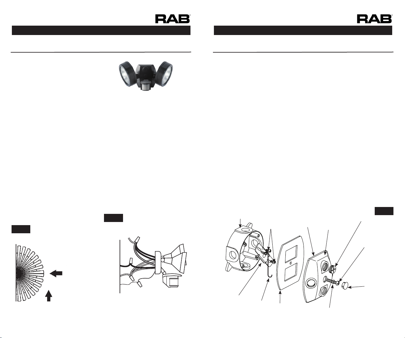
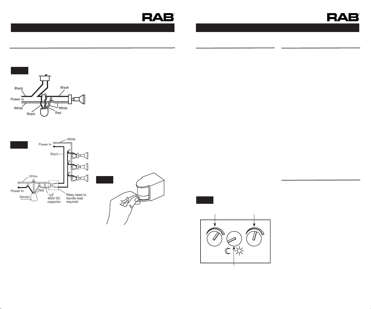
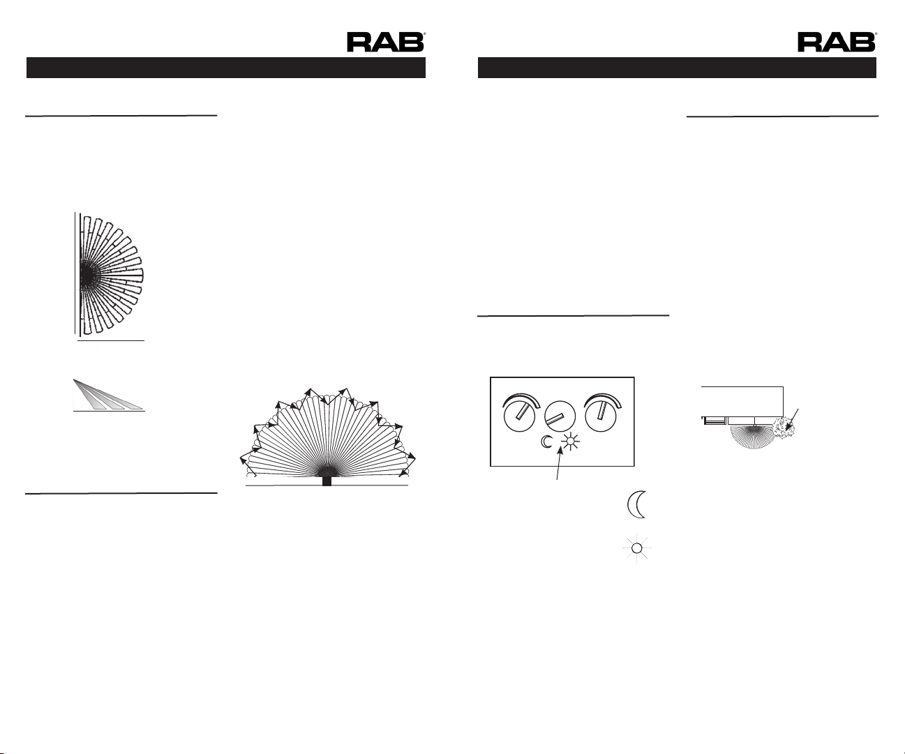
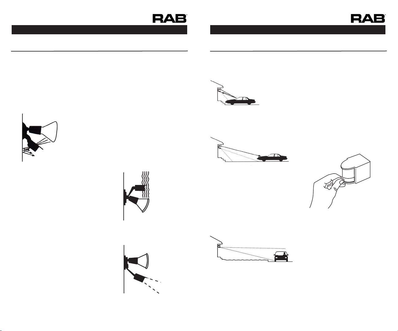
SMSLES2X13 INSTALLATION
INSTRUCTIONS
SMSLES2X13 INSTALLATION
RAB Lighting is committed to creating high-quality, aordable, well-designed and energy-ecient LED lighting and controls that make it easy for electricians to install
and
end
users
to
save
energy
.
We
’d
love
to
hear
your
comments.
Please
call
the
Marketing
Department
at
888-RAB-1000
or
email:
[email protected]RAB Lighting is committed to creating high-quality, aordable, well-designed and energy-ecient LED lighting and controls that make it easy for electricians to install
and
end
users
to
save
energy
.
We
’d
love
to
hear
your
comments.
Please
call
the
Marketing
Department
at
888-RAB-1000
or
email:
[email protected] Page 15 Page 16
If you need technical assistance, please do
the following:
1. Re-read the Technical Tips sections of
this manual.
2. Call the Tech Help Line at 888 RAB-
1000, 8AM to 6PM Eastern Time M-F
and we will be glad to help you.
Before you call, please have the
following information handy
a) Catalog number of your unit;
b) Wattage, types and locations of
lights connected to the sensor;
c) The electrical circuit on which the
sensor is installed. What else does
it feed? How is the sensor power
switched?
d) Serial Number (4 digits) on the back
of the sensor.
e) This installation Manual:
RAB Lighting cannot give electrical wiring
instructions by phone. Please consult a
qualied electrician
RAB Sensor Warranty
The SMARTBULLET RAB Sensor will be free from
defects in materials and workmanship for a
period of ten (10) years from the date of delivery
to the end-user.
Sensors must be installed by a properly
insured and licensed electrician or under the
supervision of a licensed electrician and the
product must be in its original, unopened
and new condition at the time of installation.
The information provided in the RAB Sensor
Owner’s Manual is critical in determining the
location, conditions, intended use and other
requirements with respect to the use and
installation of a sensor product. Using a sensor
product in any manner other than as disclosed
in the RAB Owner’s Manual automatically voids
the warranty.
Exceptions. The above warranties shall not apply
and RAB makes no representations or warranties
with respect to:
a. problems caused by acts of God including
without limitation lightning strikes; and
b. problems caused by any improper action or
failure to act by any person or entity other RAB,
including without limitation problems caused by
improper installation by the buyer, an authorized
RAB distributor, or any other person or entity; and
c. using or installing a sensor product in any
manner other than as disclosed in the RAB
Owner’s Manual.
d. use with Instant Start ballasts; use with Instant
Start ballasts will void the RAB warranty.
Out of warranty sensors replacement program.
If your sensor is out of warranty or if damage is
unrelated to its original manufacture, return your
sensor (freight prepaid and insured) directly to us
(at RAB Lighting Inc. 170 Ludlow Ave. Northvale,
NJ 07647) with a check for $50.00 made payable
to RAB Lighting Inc. We will repair or replace your
sensor promptly.
RAB Product Warranties
The following warranties apply to RAB Lighting,
Inc. (“RAB”) products that meet all of the
following conditions: (a) the product was
purchased by the contractor or end-user from
an authorized RAB distributor who purchased
the product directly from RAB and from no other
source; (b) if the product has been installed,
the entire installation was performed by a
licensed electrician or under the supervision of
a licensed electrician and the product was in its
original, unopened and new condition at the
time of installation. RAB LIGHTING DISCLAIMS
ALL REPRESENTATIONS AND WARRANTIES WITH
RESPECT TO ALL OTHER PRODUCTS, INCLUDING
WITHOUT LIMITATION PRODUCTS THAT HAVE
BEEN PURCHASED FROM ANY PERSON OR
ENTITY OTHER THAN AN AUTHORIZED RAB
DISTRIBUTOR, OR INSTALLED BY ANY PERSON OR
ENTITY OTHER THAN A LICENSED ELECTRICIAN
OR UNDER THE SUPERVISION OF A LICENSED
ELECTRICIAN, AND ALL PRODUCTS THAT
ARE USED OR ARE OTHERWISE NOT IN THEIR
ORIGINAL RAB LIGHTING PACKAGING AT THE
TIME OF INSTALLATION.
Remedy. RAB’s obligations for breach
of warranty shall be limited to repair or
replacement, at RAB’s option, of any products
or parts which prove to be defective, provided
that buyer gives RAB written notice and returns
the defective product to RAB in accordance with
RAB’s return material authorization (RMA) policies,
and RAB conrms the defect. Buyer is responsible
for all costs to de-install defective products and
re-install replacement or repaired products and
RAB shall not be liable for labor or other costs
related to de-installation or re-installation.
DISCLAIMER. THE FOREGOING WARRANTIES ARE
IN LIEU OF, AND RAB EXPRESSLY DISCLAIMS, ALL
OTHER REPRESENTATIONS, GUARANTEES AND
WARRANTIES, EXPRESS OR IMPLIED IN FACT OR
Note: These instructions do not cover all
details or variations in equipment nor do they
provide for every possible situation during
installation operation or maintenance.
RAB WARRANTIES RAB WARRANTIES
TOLL FREE
TECHNICAL ASSISTANCE
BY LAW, INCLUDING WITHOUT LIMITATION ALL
WARRANTIES OF MERCHANTABILITY OR FITNESS
FOR A PARTICULAR PURPOSE OR OTHERWISE.
THE FOREGOING WARRANTIES STATE RAB’S
ENTIRE AND EXCLUSIVE LIABILITY, AND BUYER’S
SOLE AND EXCLUSIVE REMEDY, IN CONNECTION
WITH THE PRODUCTS AND ALL PARTS, THEIR
DESIGN, SUITABILITY FOR USE, INSTALLATION
AND OPERATION.
LIMITATION OF LIABILITY. RAB shall not be
liable under any theory of relief, including
without limitation breach of warranty, breach
of contract, tort (including negligence), strict
liability, or otherwise, arising out of or related to
any breach of warranty, any RAB products and
the use thereof, or any other acts or omissions
of RAB for: (i) any indirect, incidental, special or
consequential damages, whatsoever (including
without limitation, loss of anticipated value of a
business or its reputation) or (ii) any damage or
loss in excess of the price actually paid by buyer
to the authorized RAB distributor for the products
that caused the damages. Any action by buyer
must be commenced within one year after the
cause of action has accrued.
Miscellaneous. These product warranty terms
shall be governed by the laws of the State
of New York. Buyer consents to the personal
jurisdiction and venue of the courts of the State
of New York. Any legal or equitable claim of
any nature arising hereunder shall be led and
maintained in the state or federal courts in the
State of New York and buyer agrees that such
courts are a convenient forum for adjudication.
In the event that suit is necessary to recover
amounts owed RAB, buyer shall be liable for
reasonable attorney’s fees, interest and costs
of collection. No agreement or understanding
varying the terms and conditions hereof shall
be binding upon RAB or buyer unless in writing
and signed by duly authorized representatives of
both parties. These product warranty terms shall
inure to the benet of and be binding upon the
parties hereto and their respective successors
and assigns.