R&G LP0197BK User manual

LP0197
R&G Racing
Unit 1, Shelley’s Lane, East Worldham, Alton, Hampshire, GU34 3AQ
Tel: +44 (0)1420 89007 Fax: +44 (0)1420 87301 www.rg-racing.com Email: info@rg-racing.com
1
Page | 1
FITTING INSTRUCTIONS FOR LP0197BK LICENCE PLATE BRACKET
YAMAHA XSR900 ’16-
THIS KIT CONTAINS THE ITEMS PICTURED AND LABELLED BELOW.
DO NOT PROCEED UNTIL YOU ARE SURE ALL PARTS ARE PRESENT.
Please note that the way the kit is packed does not necessarily represent the way of
mounting to the bike
THE PARTS SHOWN MAY BE REPRESENTATIVE ONLY (FOR CLARITY OF INSTRUCTIONS ONLY)
13
14
15
16
18
19
17
20

LP0197
R&G Racing
Unit 1, Shelley’s Lane, East Worldham, Alton, Hampshire, GU34 3AQ
Tel: +44 (0)1420 89007 Fax: +44 (0)1420 87301 www.rg-racing.com Email: info@rg-racing.com
2
Page | 2
LEGEND
ITEM 1 = M6 x 16mm LONG BUTTON HEAD BOLTS (x4)
ITEM 2 = M6 WASHERS (x8)
ITEM 3 = SUB-FRAME (FOR ILLUSTRATION ONLY)
ITEM 4 = LICENCE PLATE BRACKET (TB0197BK) (x1)
ITEM 5 = M3 NUTS (x2).
ITEM 6 = M3 WASHERS (x2).
ITEM 7 = RUBBER GROMMET FOR KEY LOCK COVER (RB0004) (x1).
ITEM 8 = RUBBER GROMMET FOR TAIL LIGHT WIRING (RB0002) (x1).
ITEM 9 = O-RING FOR RUBBER GROMMETS (OR0006) (x2).
ITEM 10 = M6 NYLOC NUTS (x4)
ITEM 11 = TAIL LIGHT SHROUD (LA0003 SHROUD) (x1)
ITEM 12 = TAIL LIGHT ASSEMBLY (LA0003) (x1)
ITEM 13 = OEM INDICATOR ADAPTERS (I0037) (x2)
ITEM 14 = MINI INDICATOR ADAPTERS (I0016) (x4)
ITEM 15 = 180mm HEAT SHRINK TUBE (x3)
ITEM 16 = TAIL LIGHT CONNECTOR (CON0040) (x1)
ITEM 17 = INDICATOR CONNECTOR (CON0027) (x2)
ITEM 18 = SMALL CABLE TIES (x3)
ITEM 19 = REFLECTOR (x1)
ITEM 20 = TAIL LIGHT RESISTOR (CON0048) (x1)
Please note that in cases where kits are packed with rubber washers holding the components
onto the bolt –the rubber washers should be thrown away!
TOOLS REQUIRED
Set of metric Allen keys
8mm and10mm Socket and wrench.
Electrical pliers/ crimps
Phillips screwdriver.
PICTURE 1PICTURE 2

LP0197
R&G Racing
Unit 1, Shelley’s Lane, East Worldham, Alton, Hampshire, GU34 3AQ
Tel: +44 (0)1420 89007 Fax: +44 (0)1420 87301 www.rg-racing.com Email: info@rg-racing.com
4
Page | 4
PICTURE 9 PICTURE 10
PICTURE 11 PICTURE 12
FITTING INSTRUCTIONS
Remove the seat using the key.
Remove the four bolts that hold the seat lock mechanism (arrowed in picture 1) using
8mm socket and a wrench.
Slide off the wires protective cover and disconnect all tail unit connectors (rear light, both
indicators and licence plate light connectors) as shown in picture 2. Please take note of
the routing and where each connector connects to.
Remove the four bolts arrowed in picture 3 and gently retract the OEM tail unit assembly
and its wiring away from the sub-frame. Please note to keep the tail unit supported while
the bolts are being undone.
On the OEM tail unit assembly, working from underneath, remove the seat lock/ cable
cover by removing the two plastic expanders (arrowed in picture 4) using a phillip
screwdriver. Slide the cover backwards to remove it completely.
Remove the cable tie that holds the wiring bundle and unclip the two clips holding the
indicator wires onto the OEM tail unit bracket (as arrowed in picture 5)
If using the original indicators
Remove the spreader/ location plate arrowed in picture 6.
Gently squeeze the indicator stem and remove the indicator together with its wires.
Insert the OEM Indicator adapter (Item 13) into the indicator stem as shown in picture 7.
A

LP0197
R&G Racing
Unit 1, Shelley’s Lane, East Worldham, Alton, Hampshire, GU34 3AQ
Tel: +44 (0)1420 89007 Fax: +44 (0)1420 87301 www.rg-racing.com Email: info@rg-racing.com
5
Page | 5
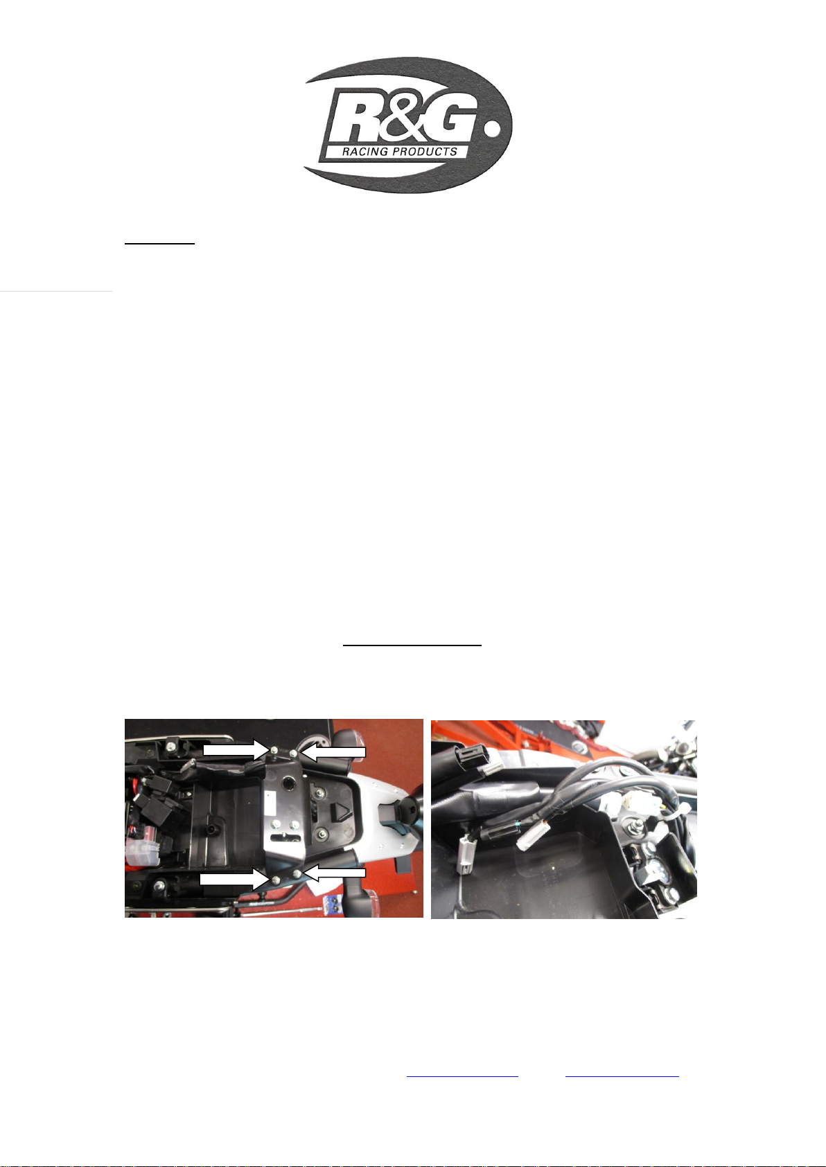
Fit the original indicator with the adapter to the new licence plate bracket (Item 4) and re-
fit the spreader. Ensure that the adapter (Item 13) is sitting on the outside of the licence
plate bracket (Item 4).
Repeat the procedure for the other indicator.
If fitting R&G mini indicators (R&G product code RG370=bulb, RG371=LED or RG372 = Aero LED
If fitting the R&G Mini Indicators, cut the heat-shrink tube (Item 15) into a suitable
length and insert the two wires coming from the indicator through. Please leave at least
50mm of wires uncovered by the heat shrink tube as bullet connectors are needed to be
attached to it. Position and crimp male bullet connectors to the exposed wires, ensuring
the connections are secured and the exposed wire end is in contact with the bullet
connector. Using a suitable heating resources, shrink the heat-shrink tube.
Using an indicator connector (Item 17) from the kit, plug in the female connectors into
the male connectors just fitted on the indicator wires.
Use the indicator adapters (item 14) on either side of the bracket and tighten the
assembly.
Repeat procedure to the other mini indicator.
Fitting the Tail Light
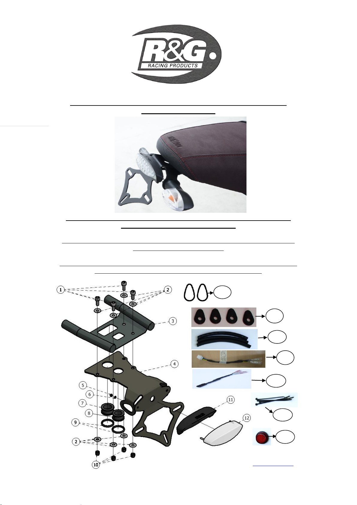
From the kit, take the Tail light unit (Item 12) and its shroud (Item 11). Insert the tail light
into the shroud by aligning the two studs at the back of the tail light into the two holes
provided on the shroud. Mount the whole assembly into the new licence plate bracket
(Item 4) and secure with M3 washers (Item 6) and M3 Nuts (Item 5). Tighten the M3 nuts
(Item 5).
Cut the Heat-shrink tube (Item 15) into a suitable length and feed the three wires through,
please leave at least 50mm of wires uncovered by the heat shrink tube as bullet
connectors are needed to be attached to it. Using a suitable heating resources, shrink the
heat-shrink tube.
Using suitable tool, install the male bullet connectors onto the exposed wiring from the
tail light unit. Crimp the bullet connector, check for tightness and make sure the exposed
wire is in contact with the bullet connector. Repeat this procedure to all three wires.
Plug in the Tail light resistor (Item 20) from the kit onto the male bullet connector just
fitted on the tail light unit. Please connect the wires in the orientation below:
RESISTOR YELLOW ------------------YELLOW (TAIL LIGHT)
RESISTOR RED -------------------------RED (TAIL LIGHT)
RESISTOR BLACK---------------------BLACK (TAIL LIGHT)
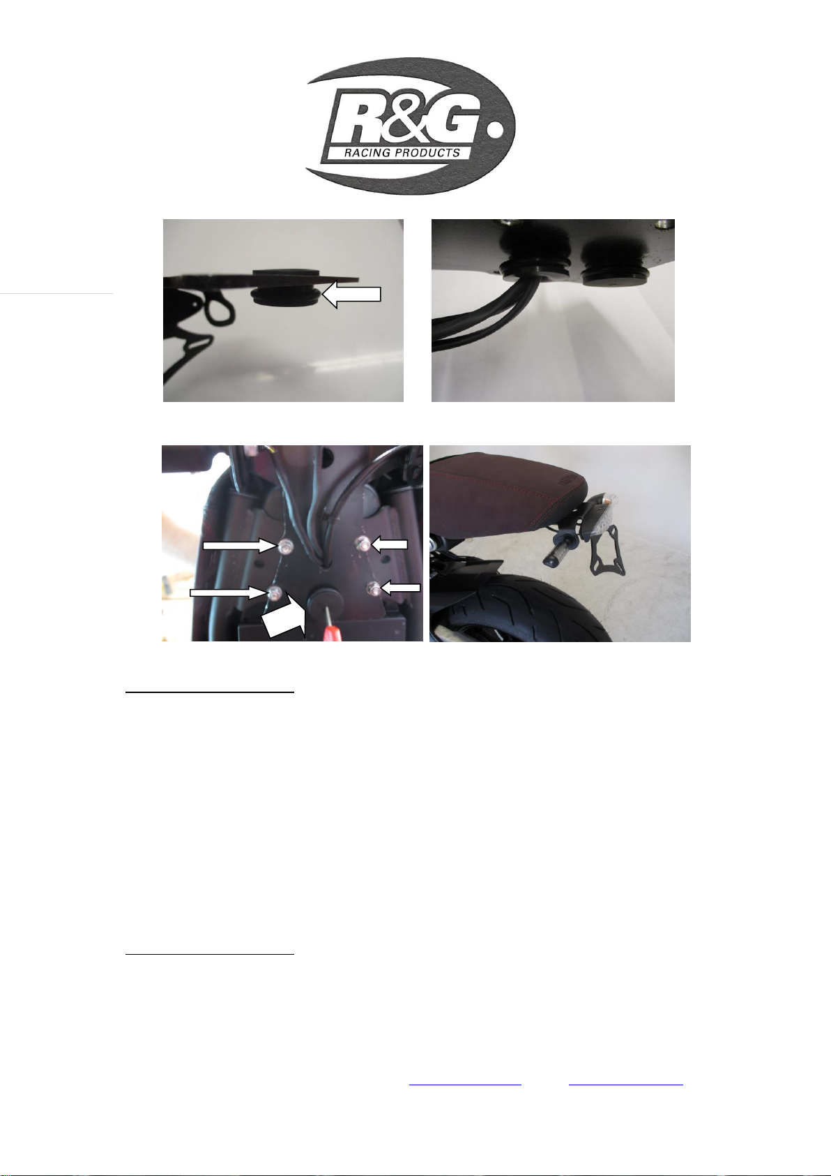
From the kit, take the 26mm rubber grommet (Item 7) and fit the O-ring (Item 9) provided
over it as shown in picture 8.
Gently squeeze the rubber grommet and insert it into a larger hole on the licence plate
bracket (Item 4) as arrowed in picture 9. Ensure that the O-rings sits below the licence
plate bracket (Item 7).
Repeat the procedure to the other rubber grommet (Item 8)
Gently push all the wiring (Both indicators and tail light wiring) through the smaller
rubber grommet (Item 8) as shown in picture 10.
Bring the whole assembly towards the sub-frame, gently insert the larger rubber grommet
(Item 7) over the key lock (labelled A in picture 11). For an easier fitment, rub a thin
layer of wd40 or equivalent around the outer surface of the key lock and slide the rubber
grommet (item 7) in.

LP0197
R&G Racing
Unit 1, Shelley’s Lane, East Worldham, Alton, Hampshire, GU34 3AQ
Tel: +44 (0)1420 89007 Fax: +44 (0)1420 87301 www.rg-racing.com Email: info@rg-racing.com
6
Page | 6
Mount the licence plate bracket (Item 4) using the four M6 x 16mm (Item 1) with M6
washers (Item 2) through the top four holes on the sub-frame. Secure the assembly with
M6 washer (Item 2) and M6 nyloc nut (Item 10) on each bolt as arrowed in picture 11.
Ensure that none of the wires are caught between the sub-frame and the licence plate
bracket (item 4). Tighten the four nyloc nuts (Item 10) using 5mm Allen key, 10mm
socket and a wrench to 12 Nm.
Reconnect all the indicator wiring plug sockets and check operation (if illumination fails,
swap the bullet connections around).
Connect the tail light resistor (Item 20) to the tail light connector (Item 16) in this
scheme: RESISTOR BLUE ------------CONNECTOR YELLOW
RESISTOR YELLOW -------CONNECTOR BLUE
RESISTOR BLACK ----------CONNECTOR BLACK
Connect the male connector of the tail light connector (Item 16) into the OEM female
connector in the main wiring loom.
Route the wiring as original and tidy up using the cable ties provided from the kit.
OEM number plate light connector is no longer in use as the tail light unit (Item 12)
comes with built-in LED licence plate lights.
Fit licence plate to the new licence plate bracket (Item 4) (it may require re-drilling).
IMPORTANT: IF FITTING A FULL-SIZE LICENCE PLATE AND PLACING IT
FAR DOWN ON THE LICENCE PLATE HANGER, THERE IS A SMALL
CHANCE OF THE LICENCE PLATE HITTING THE BACK WHEEL UNDER
HEAVY LOAD AND OVER LARGE BUMPS IN THE ROAD. IT IS YOUR
RESPONSIBILITY TO CHECK FOR THIS POSSIBILITY AND TAKE
AVOIDING ACTION. FAILURE TO CHECK THIS COULD RESULT IN
SERIOUS INJURY.
Refit the Seat lock mechanism as original using its original bolts.
Refit seat.
Depending on local laws, attach enclosed red reflector (item 19) in an appropriate
location.
Please test the indicators, rear light, no. plate light and brake light before riding.
Digital copies of these instructions are available to download from www.rg-racing.com
GENERAL TORQUE SETTINGS
M4 BOLT = 8Nm
M5 BOLT = 12Nm
M6 BOLT = 15Nm
M8 BOLT = 20Nm
M10 BOLT = 40Nm
ISSUE 4 04/11/2016 (HH)
CONSUMER NOTICE
The catalogue description and any exhibition of samples are only broad indications of the Products and R&G may make design
changes which do not diminish their performance or visual appeal and supplying them in such state shall conform to the order.
The Buyer acknowledges no representation or warranty (other than as to title) has been given or will apply to the Products other
than those in R&G’s order or confirmation and the Buyer confirms it has chosen the Products as being of merchantable quality
and suitable for its particular purposes. Where R&G fits the Products or undertakes other services it shall exercise reasonable
skill and care and rectify any fault free of charge unless the workmanship has been disturbed. The Buyer is responsible for
ensuring that the warranty on the motorcycle is not affected by the fitting of the Products. On return of any defective Products

LP0197
R&G Racing
Unit 1, Shelley’s Lane, East Worldham, Alton, Hampshire, GU34 3AQ
Tel: +44 (0)1420 89007 Fax: +44 (0)1420 87301 www.rg-racing.com Email: info@rg-racing.com
7
Page | 7
R&G shall at its option either supply a replacement or refund the purchase money but shall not be liable if the Products have
been modified or used or maintained otherwise than in accordance with R&G’s or manufacturer’s instructions and good
engineering practice or if the defect arises from accident or neglect. Other than identified above and subject to R&G not limiting
its liability for causing death and personal injury, it shall not be liable for indirect or consequential loss and otherwise its liability
shall be limited to the amounts paid by the Buyer for the Products or the fitting or service concerned. These terms do not affect
the Buyer’s statutory rights.
R&G RACING RETURNS POLICY (NON-FAULTY GOODS)
Returns must be pre-authorised (if not pre-authorised the return will be rejected). Goods may only be returned direct to us if they
were purchased direct from us (customer must prove if necessary). Otherwise to be returned to original vendor. Goods must be
in re-sellable condition, in the opinion of R&G Racing. All returns are subject to a 25% restocking and handling fee (25% of the
gross value exc. P&P –at the prevailing price at time of purchase). The customer must pay any and all carriage charges. No
returns of discontinued products, unless within 14 days of purchase. This policy does not affect your statutory rights and does not
refer to faulty goods.

LP0197
R&G Racing
Unit 1, Shelley’s Lane, East Worldham, Alton, Hampshire, GU34 3AQ
Tel: +44 (0)1420 89007 Fax: +44 (0)1420 87301 www.rg-racing.com Email: info@rg-racing.com
8
Page | 8
NOTICE DE MONTAGE POUR LP0197BK SUPPORT DE PLAQUE
YAMAHA XSR900 ’16-
Le kit contient les articles exposés ci-dessous, vérifier que toutes les pièces soient
présentes avant de procéder au montage.
LA FAÇON DONT LE KIT EST EMBALLE NE CORRESPOND PAS FORCEMENT A LA FAÇON DE
MONTER LES PIECES SUR LA MOTO
LES PARTIES PRESENTEES PEUVENT ETRE UNIQUEMENT REPRESENTATIVES
(POUR LA CLARTE DES INSTRUCTIONS UNIQUEMENT)
13
14
15
16
18
19
17

LP0197
R&G Racing
Unit 1, Shelley’s Lane, East Worldham, Alton, Hampshire, GU34 3AQ
Tel: +44 (0)1420 89007 Fax: +44 (0)1420 87301 www.rg-racing.com Email: info@rg-racing.com
9
Page | 9
LEGENDE
ARTICLE 1 = M6 x 16mm BOULONS (x4)
ARTICLE 2 = M6 RONDELLES (x8)
ARTICLE 3 = SOUS CADRE (POUR ILLUSTRER UNIQUEMENT)
ARTICLE 4 = SUPPORT DE PLAQUE (TB0197BK) (x1)
ARTICLE 5 = M3 ECROUS (x2).
ARTICLE 6 = M3 RONDELLES (x2).
ARTICLE 7 = RONDELLE DE CAOUTCHOUC POUR CACHE SERRURE (RB0004) (x1).
ARTICLE 8 = RONDELLE DE CAOUTCHOUC POUR CABLES DE FEU (RB0002) (x1).
ARTICLE 9 = BAGUE O POUR RONDELLES DE CAOUTCHOUC (OR0006) (x2).
ARTICLE 10 = M6 ECROUS (x4)
ARTICLE 11 = LINCEUL DE FEU (LA0003) (x1)
ARTICLE 12 = ASSEMBLAGE FEU DE PLAQUE (LA0003) (x1)
ARTICLE 13 = ADAPTATEURS CLIGNOTANTS D’ORIGINE (I0037) (x2)
ARTICLE 14 = ADAPTATEURS MINI CLIGNOTANT (I0016) (x4)
ARTICLE 15 = TUBE THERMO RETRACTABLE 180mm (x3)
ARTICLE 16 = EXTENSIONS DE FIL (CON0040) (x1)
ARTICLE 17 = CONNECTEUR CLIGNOTANT (CON0027) (x2)
ARTICLE 18 = PETITS COLLIERS DE SERRAGE (x3)
ARTICLE 19 = REFLECTEUR (x1)
ARTICLE 20 = RESISTANCE DE FEU (CON0048) (x1)
Notez que si les kits sont emballés avec des rondelles en caoutchouc servant à tenir les
composants, ces rondelles doivent être jetées !
OUTILS REQUIS
Clé Allen
Clé anglaise / à tube : 8mm et 10mm.
Pinces électriques
Tournevis cruciforme.
PHOTO 1PHOTO 2
20

LP0197
R&G Racing
Unit 1, Shelley’s Lane, East Worldham, Alton, Hampshire, GU34 3AQ
Tel: +44 (0)1420 89007 Fax: +44 (0)1420 87301 www.rg-racing.com Email: info@rg-racing.com
11
Page | 11
PHOTO 9 PHOTO 10
PHOTO 11 PHOTO 12
NOTICE DE MONTAGE
Enlever le siège à l’aide de la clé.
Enlever les 4 boulons qui fixent le mécanisme de blocage du siège (photo 1) avec une clé
de 8mm.
Glisse le cache de protection des fils et déconnecter tous les connecteurs de l’unité de
support de plaque (feu arrière, les 2 clignotants et les connecteurs de feu de plaque) voir
photo 2. Prendre note de l’organisation des fils et de l’emplacement de chaque
connecteur.
Enlever les 4 boulons, voir photo 3 et rétracter l’assemblage du support d’origine et
écarter les fils du sous cadre. NOTE : Supportez le support lorsque vous enlevez les
boulons.
Sur l’assemblage d’origine, travailler par dessous, enlever le cache blocage de
siège/câble en enlevant les 2 épandeurs en plastique (photo 4) l’aide d’un tournevis
cruciforme. Glisser le cache vers le bas pour l’enlever complètement.
A

LP0197
R&G Racing
Unit 1, Shelley’s Lane, East Worldham, Alton, Hampshire, GU34 3AQ
Tel: +44 (0)1420 89007 Fax: +44 (0)1420 87301 www.rg-racing.com Email: info@rg-racing.com
12
Page | 12
Enlever le collier de serrage qui fixe la liasse de fils puis déclipser les 2 clips qui
maintiennent les fils de clignotant sur l’unité de support de plaque d’origine (voir photo
5).
Si vous utilisez les clignotants d’origine :
Retirer l’épandeur/ plaque d’emplacement, voir photo 6.
Pressez la tige de clignotant et enlever le clignotant avec ses fils.
Insérer l’adaptateur de clignotant d’origine (Article 13) dans la tige de clignotant, voir
photo 7.
Monter le clignotant d’origine avec l’adaptateur sur le nouveau support de plaque
(Article 4) puis remonter l’épandeur. Veiller à ce que l’adaptateur (Article 13) soit placé à
l’extérieur du support de plaque (Article 4)
Répéter la procédure pour l’autre clignotant.
Si vous montez les mini clignotants R&G (R&G code produit RG370=ampoule, RG371=LED ou RG372 =
LED latérale
Si vous montez les minis clignotants R&G, coupez le tube thermo rétractable (Article 15)
à longueur adéquate puis passer les 2 fils de clignotants au travers. Svp, laissez au
minimum 50mm de fils non couverts par le tube thermo rétractable car les connecteurs
y seront attachés. Positionner et sertir le connecteur mâle sur les extrémités de fils, en
veillant à ce que les connections soient sécurisées et que l’extrémité soit en contact avec
le connecteur. Utiliser une source de chaleur adéquate pour rétreindre le tube thermo
rétractable.
Utiliser un connecteur de clignotant (Article 17) du kit, brancher les connecteurs femelle
dans les connecteurs mâles tout justes montés sur les fils de clignotants.
Utiliser les adaptateurs de clignotants (article 14) de chaque coté du support puis serrer
l’assemblage.
Répéter la procédure pour l’autre clignotant.
Monter le feu de plaque
Dans le kit, prenez l’unité de feu (Article 12) et son linceul (Article 11). Insérer le feu de
plaque dans le linceul en alignant les 2 onglets situés au bas du support de feu dans les 2
trous présents sur le linceul. Monter l’assemblage sur le nouveau support de plaque
(Article 4) puis fixer avec des rondelles M3 (Article 6) et écrous M3 (Article 5). Serrer les
écrous M3 (Article 5).
Couper le tube thermo rétractable (Article 15) à longueur adéquate et passer les 3 fils au
travers, laisser au minimum 50mm de fils non couvert par le tube thermo rétractable car
les connecteurs y seront attachés. A l’aide d’une source de chaleur adéquate, rétreindre
le tube thermo rétractable.
A l’aide d’un outil adéquat, installez les connecteurs mâles sur les fils de l’unité de feu de
plaque. Sertir le connecteur, vérifier le serrage et vérifier que le fil soit bien en contact
avec connecteur. Répéter la procédure sur les 3 fils.
Brancher la résistance du feu de support (Article 20) du kit sur le connecteur mâle tout
juste monté sur l’unité de support de feu de plaque. SVP connecter les fils selon ce
schéma :
RESISTANCE JAUNE ------------------JAUNE (FEU DE PLAQUE)
RESISTANCE ROUGE -------------------------ROUGE (FEU DE PLAQUE)

LP0197
R&G Racing
Unit 1, Shelley’s Lane, East Worldham, Alton, Hampshire, GU34 3AQ
Tel: +44 (0)1420 89007 Fax: +44 (0)1420 87301 www.rg-racing.com Email: info@rg-racing.com
13
Page | 13
RESISTANCE NOIRE---------------------NOIR (FEU DE PLAQUE)
Prendre la rondelle caoutchouc 26mm du kit (Article 7) et placer la bague O (Article 9)
fournie autour d’elle, voir photo 8.
Presser doucement la rondelle de caoutchouc et insérez la dans le trou plus large sur le
support de plaque (Article 4) voir photo 9. Veiller à ce que les bagues O se place au
dessous du support de plaque (Article 7).
Répéter la procédure pour l’autre rondelle de caoutchouc (Article 8).
Pousser tous les fils doucement (Les 2 clignotants et le fil de feu de plaque) dans la
rondelle de caoutchouc plus petite (Article 8) voir photo 10.
Porter l’ensemble contre le sous cadre, insérer la rondelle de caoutchouc la plus large
(Article 7) sur la serrure (étiquette A sur la photo 11). Pour une installation plus facile,
frotter une fine couche de wd40 ou équivalent autour de la face externe de la serrure
puis glisser la rondelle de caoutchouc (article 7) dedans.
Monter le support de plaque (Article 4) à l’aide des 4 boulons M6 x 16mm (Article 1)
avec rondelles M6 (Article 2) dans les 4 trous supérieurs du sous cadre. Fixer l’ensemble
avec une rondelle M6 (Article 2) et un écrou M6 (Article 10) sur chaque boulon, voir
photo 11.
Veiller à ce qu’aucun des fils ne puisse être pincé entre le sous cadre et le support de
plaque (article 4). Serrer les 4 écrous (Article 10) avec une clé Allen 5mm, et une clé
dynamométrique de 10mm à 12 Nm.
Reconnecter toutes les prises de clignotants et vérifier le fonctionnement (si l’éclairage
échoue, tournez les connecteurs).
Connecter la résistance de feu de support (Article 21) sur le connecteur de feu de plaque
(Article 16) selon ce schéma:
RESISTANCE BLUE ------------CONNECTEUR JAUNE
RESISTANCE JAUNE -------CONNECTEUR BLEU
RESISTANCE NOIR ----------CONNECTEUR NOIR
Connecter le connecteur mâle du connecteur de feu de plaque (Article 16) dans le connecteur
femelle d’origine dans le faisceau de câbles principal.
Ranger les fils comme à l’origine et serrer à l’aide de colliers de serrage fournis dans le
kit.
Le connecteur de feu de plaque d’origine n’est plus opérationnel car l’unité de feu de
plaque (Article 12) vient avec les feux de plaque LED.
Monter la plaque d’immatriculation sur le nouveau support de plaque (Article 4) (cette
opération peut nécessiter un perçage).
IMPORTANT: Si vous installez une grosse plaque, il y a un risque que la plaque entre en
contact avec la roue arrière en cas de choc sur la route (bosse, grosse charge etc...). Il
est de votre responsabilité de vérifier que cela ne puisse pas se produire. Ne pas
effectuer ces vérifications peut entrainer des dommages ainsi que des blessures graves
pour le pilote.
Remonter le mécanisme de blocage comme à l’origine, à l’aide des boulons d’origine.
Remettre le siège.
Selon la loi locale, attachez le réflecteur (article 19) fourni à son emplacement approprié

LP0197
R&G Racing
Unit 1, Shelley’s Lane, East Worldham, Alton, Hampshire, GU34 3AQ
Tel: +44 (0)1420 89007 Fax: +44 (0)1420 87301 www.rg-racing.com Email: info@rg-racing.com
14
Page | 14
Vérifiez que les clignotants et les feux de plaque fonctionnent bien avant de prendre la
route.
Notice disponible au téléchargement sur www.rg-racing.com
COUPLES DE SERRAGE RECOMMANDES
M4 BOULON = 8Nm
M5 BOULON = 12Nm
M6 BOULON = 15Nm
M8 BOULON = 20Nm
M10 BOULON = 40Nm
ISSUE 4 04/11/2016 (HH)
CONSUMER NOTICE
The catalogue description and any exhibition of samples are only broad indications of the Products and R&G may make design
changes which do not diminish their performance or visual appeal and supplying them in such state shall conform to the order.
The Buyer acknowledges no representation or warranty (other than as to title) has been given or will apply to the Products other
than those in R&G’s order or confirmation and the Buyer confirms it has chosen the Products as being of merchantable quality
and suitable for its particular purposes. Where R&G fits the Products or undertakes other services it shall exercise reasonable
skill and care and rectify any fault free of charge unless the workmanship has been disturbed. The Buyer is responsible for
ensuring that the warranty on the motorcycle is not affected by the fitting of the Products. On return of any defective Products
R&G shall at its option either supply a replacement or refund the purchase money but shall not be liable if the Products have
been modified or used or maintained otherwise than in accordance with R&G’s or manufacturer’s instructions and good
engineering practice or if the defect arises from accident or neglect. Other than identified above and subject to R&G not limiting
its liability for causing death and personal injury, it shall not be liable for indirect or consequential loss and otherwise its liability
shall be limited to the amounts paid by the Buyer for the Products or the fitting or service concerned. These terms do not affect
the Buyer’s statutory rights.
R&G RACING RETURNS POLICY (NON-FAULTY GOODS)
Returns must be pre-authorised (if not pre-authorised the return will be rejected). Goods may only be returned direct to us if they
were purchased direct from us (customer must prove if necessary). Otherwise to be returned to original vendor. Goods must be
in re-sellable condition, in the opinion of R&G Racing. All returns are subject to a 25% restocking and handling fee (25% of the
gross value exc. P&P –at the prevailing price at time of purchase). The customer must pay any and all carriage charges. No
returns of discontinued products, unless within 14 days of purchase. This policy does not affect your statutory rights and does not
refer to faulty goods.
Table of contents
Languages:
Other R&G Motorcycle Accessories manuals