R&G RAD0262 User manual

Page 1of 17 RAD0262
R&G Racing
Unit 1, Shelley’s Lane, East Worldham, Alton, Hampshire, GU34 3AQ
Tel: +44 (0)1420 89007 Fax: +44 (0)1420 87301 www.rg-racing.com Email: info@rg-racing.com
FITTING INSTRUCTIONS FOR RAD0262
RADIATOR GUARD
MV AGUSTA BRUTALE 1000 RR 2020-
THIS KIT CONTAINS THE ITEMS PICTURED AND LABELLED OVER PAGE.
SOME PARTS MAY BE SHOWN FOR CLARITY OF INSTRUCTIONS ONLY.
DO NOT PROCEED UNTIL YOU ARE SURE ALL PARTS ARE PRESENT.
PLEASE READ ALL INSTRUCTIONS BEFORE PROCEEDING.
IF IN ANY DOUBT WHEN FITTING OUR PRODUCTS, CONSULT ONE OF OUR DEALERS
OR HAVE FITTED BY A QUALIFIED TECHNICIAN.
PLEASE NOTE THAT THE WAY THE KIT IS PACKED DOES NOT NECESSARILY REPRESENT THE WAY OF
MOUNTING TO THE BIKE.
IN THE EVENT OF RUBBER WASHERS BEING USED TO HOLD COMPONENTS ONTO BOLTS,
THESE RUBBER WASHERS CAN BE THROWN AWAY.
DIGITAL COPIES OF THESE INSTRUCTIONS ARE AVAILABLE FROM:
WWW.RG-RACING.COM

Page 2of 17 RAD0262
R&G Racing
Unit 1, Shelley’s Lane, East Worldham, Alton, Hampshire, GU34 3AQ
Tel: +44 (0)1420 89007 Fax: +44 (0)1420 87301 www.rg-racing.com Email: info@rg-racing.com
TOOLS REQUIRED
•Metric Allen Key set
•Clippers & Scissors
GENERAL TORQUE SETTINGS
M4 BOLT = 8Nm
M5 BOLT = 12Nm
M6 BOLT = 15Nm
M8 BOLT = 20Nm
M10 BOLT = 40Nm
M12 BOLT = 40Nm
LEGEND
ITEM NO.
DESCRIPTION
QTY
ITEM 1
RAD0262 RADIATOR GUARD
1
ITEM 2
100mm LENGTH OF SELF-ADHESIVE FOAM
2
ITEM 3
CABLE TIES (CT220)
6

Page 5of 17 RAD0262
R&G Racing
Unit 1, Shelley’s Lane, East Worldham, Alton, Hampshire, GU34 3AQ
Tel: +44 (0)1420 89007 Fax: +44 (0)1420 87301 www.rg-racing.com Email: info@rg-racing.com
FITTING INSTRUCTIONS:
FAIRING PANEL REMOVAL:
•Remove the bolts shown in Image 1 using a 4mm Allen key.
•Using the same size Allen key remove the hidden bolt inside of the fairing panel
(shown in Images 2 & 3).
•You may now gently remove the upper panel from the pin on the tank (Image 4) &
store it safely until you are ready to re-install.
•Removing the lower panel requires the removal of the two bolts seen in Image 5
which are revealed after the removal of the upper panel.
•Once the two upper mounting bolts have been removed, the lower mounting bolt
(shown in Image 6) will be the only bolt holding the lower panel in position, so be
sure to support the panel while removing the final bolt.
•Repeat these steps for the remaining fairing panels on the other side of the
motorcycle.
OIL COOLER SHROUD REMOVAL:
•Once both lower bolts pictured in Image 6 have been removed, the oil cooler shroud
will only be held in position by a rubber mounted pin, so be sure to either
immediately remove the shroud or support the shroud until you are ready to do so.
•Once the LHS & RHS fairing panels have been removed the oil cooler shroud will be
held in position by the pin shown in Image 7 at the bottom of the oil cooler.
•Lower the shroud until it can be removed from the pin, then store away safely until
ready to re-install.
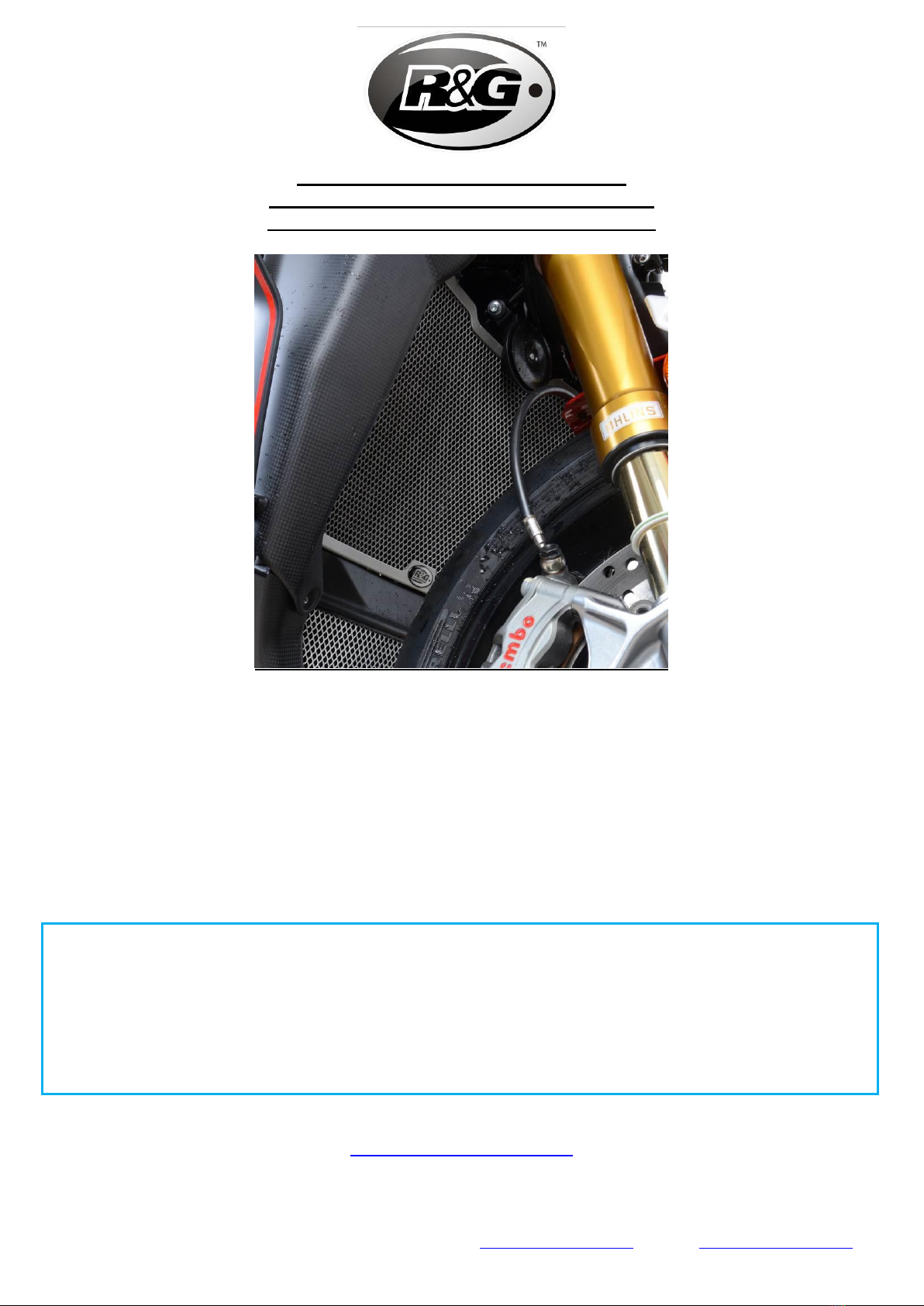
RADIATOR GUARD INSTALLATION:
•Now all fairing panels have been removed, the radiator mounting points will be
accessible. (Image 8)
•Cut & apply the supplied adhesive foam in various positions around the back side of
the radiator guard, this will protect the radiator from any rubbing & prevent any
rattling that can sometimes occur with vibration.
•Insert the top two cable ties into position on the radiator guard (shown in Image 9),
then offer up the guard to the radiator.
•Wrap the cable ties around the radiator mounting tabs and loosely zip the cable ties
up to allow fitment of the lower cable ties & fine tuning of positioning once all cable
ties are attached. (Image 10)
•Once you are happy with the position of the radiator guard, slowly tighten each cable
tie one at a time until the guard is firmly secured into position.
•Cut excess cable tie length using scissors or clippers then re-install all panels in
reverse of the order shown above.
ISSUE 1: 07/04/2021 (TB)

Page 6of 17 RAD0262
R&G Racing
Unit 1, Shelley’s Lane, East Worldham, Alton, Hampshire, GU34 3AQ
Tel: +44 (0)1420 89007 Fax: +44 (0)1420 87301 www.rg-racing.com Email: info@rg-racing.com
CONSUMER NOTICE
The catalogue description and any exhibition of samples are only broad indications of the Products and R&G may
make design changes which do not diminish their performance or visual appeal and supplying them in such state
shall conform to the order. The Buyer acknowledges no representation or warranty (other than as to title) has
been given or will apply to the Products other than those in R&G’s order or confirmation and the Buyer confirms it
has chosen the Products as being of merchantable quality and suitable for its particular purposes. Where R&G fits
the Products or undertakes other services it shall exercise reasonable skill and care and rectify any fault free of
charge unless the workmanship has been disturbed. The Buyer is responsible for ensuring that the warranty on
the motorcycle is not affected by the fitting of the Products. On return of any defective Products R&G shall at its
option either supply a replacement or refund the purchase money but shall not be liable if the Products have been
modified or used or maintained otherwise than in accordance with R&G’s or manufacturer’s instructions and good
engineering practice or if the defect arises from accident or neglect. Other than identified above and subject to
R&G not limiting its liability for causing death and personal injury, it shall not be liable for indirect or consequential
loss and otherwise its liability shall be limited to the amounts paid by the Buyer for the Products or the fitting or
service concerned. These terms do not affect the Buyer’s statutory rights.
R&G RACING RETURNS POLICY (NON-FAULTY GOODS)
Returns must be pre-authorised (if not pre-authorised the return will be rejected). Goods may only be returned
direct to us if they were purchased direct from us (customer must prove if necessary). Otherwise to be returned
to original vendor. Goods must be in re-sellable condition, in the opinion of R&G Racing. All returns are subject to
a 25% restocking and handling fee (25% of the gross value exc. P&P –at the prevailing price at time of
purchase). The customer must pay any and all carriage charges. No returns of discontinued products, unless
within 14 days of purchase. This policy does not affect your statutory rights and does not refer to faulty goods.

Page 7of 17 RAD0262
R&G Racing
Unit 1, Shelley’s Lane, East Worldham, Alton, Hampshire, GU34 3AQ
Tel: +44 (0)1420 89007 Fax: +44 (0)1420 87301 www.rg-racing.com Email: info@rg-racing.com
NOTICE DE MONTAGE RAD0262
GRILLE DE PROTECTION RADIATEUR
MV AGUSTA BRUTALE 1000 RR 2020-
CE KIT CONTIENT LES ARTICLES ILLUSTRES ET ETIQUETES SUR LA PAGE.
CERTAINES PARTIES PEUVENT ETRE PRESENTES UNIQUEMENT POUR LA CLARTE DES INSTRUCTIONS.
NE PAS PROCEDER AU MONTAGE TANT QUE VOUS N'ETES PAS SUR QUE TOUTES LES PIECES SOIENT
PRESENTES.
VEUILLEZ LIRE TOUTES LES INSTRUCTIONS AVANT DE CONTINUER.
EN CAS DE DOUTE LORS DU MONTAGE DE NOS PRODUITS, CONSULTEZ UN DE NOS
REVENDEURS OU FAITES APPEL A UN TECHNICIEN QUALIFIÉ.
VEUILLEZ NOTER QUE LA FAÇON DONT LE KIT EST EMBALLE NE REPRESENTE PAS NECESSAIREMENT LA
MANIERE DE LE MONTER SUR LA MOTO.
SI DES RONDELLES EN CAOUTCHOUC SONT UTILISEES POUR MAINTENIR LES COMPOSANTS SUR LES
BOULONS,ELLES PEUVENT ETRE JETEES.
NOTICE DISPONIBLE AU TELECHARGEMENT SUR :
WWW.RG-RACING.COM

Page 8of 17 RAD0262
R&G Racing
Unit 1, Shelley’s Lane, East Worldham, Alton, Hampshire, GU34 3AQ
Tel: +44 (0)1420 89007 Fax: +44 (0)1420 87301 www.rg-racing.com Email: info@rg-racing.com
OUTILS REQUIS
•Clés Allen
•Pinces et ciseaux
VALEURS DE SERRAGE
M4 BOULON = 8Nm
M5 BOULON = 12Nm
M6 BOULON = 15Nm
M8 BOULON = 20Nm
M10 BOULON = 40Nm
M12 BOULON = 40Nm
LÉGENDE
ARTICLE
NO.
DESCRIPTION
QTÉ
ARTICLE 1
RAD0262 GRILLE DE PROTECTION RADIATEUR
1
ARTICLE 2
100mm BANDEAU DE MOUSSE AUTOCOLLANT
2
ARTICLE 3
COLLIERS DE SERRAGE (CT220)
6

Page 11 of 17 RAD0262
R&G Racing
Unit 1, Shelley’s Lane, East Worldham, Alton, Hampshire, GU34 3AQ
Tel: +44 (0)1420 89007 Fax: +44 (0)1420 87301 www.rg-racing.com Email: info@rg-racing.com
NOTICE DE MONTAGE :
ENLEVER LE CARÉNAGE :
•Retirez les boulons illustrés sur l'image 1 à l'aide d'une clé Allen de 4 mm.
•À l'aide d'une clé Allen de même taille, retirez le boulon caché à l'intérieur du
panneau de carénage (illustré sur les images 2 et 3).
•Vous pouvez maintenant retirer doucement le panneau supérieur de la goupille sur le
réservoir (Image 4) et le ranger en toute sécurité jusqu'à ce que vous soyez prêt à le
réinstaller.
•Le retrait du panneau inférieur nécessite le retrait des deux boulons visibles sur
l'image 5 qui sont révélés après le retrait du panneau supérieur.
•Une fois les deux boulons de montage supérieurs retirés, le boulon de montage
inférieur (illustré à l'image 6) sera le seul boulon maintenant le panneau inférieur en
position, alors assurez-vous de soutenir le panneau tout en retirant le boulon final.
•Répétez ces étapes pour les panneaux de carénage restants de l'autre côté de la moto
RETIRER LE LINCEUL DE REFROIDISSEUR D’HUILE:
•Une fois que les deux boulons inférieurs illustrés sur l'image 6 ont été retirés, le
carénage du refroidisseur d'huile ne sera maintenu en position que par une goupille
montée en caoutchouc, assurez-vous donc de retirer immédiatement le carénage ou
de le soutenir jusqu'à ce que vous soyez prêt à le faire.
•Une fois que les panneaux de carénage côté gauche et côté droit ont été retirés, le
carénage du refroidisseur d'huile sera maintenu en position par la goupille illustrée
sur l'image 7 au bas du refroidisseur d'huile.
•Abaissez le carénage jusqu'à ce qu'il puisse être retiré de la goupille, puis rangez-le
en toute sécurité jusqu'à ce qu'il soit prêt à réinstaller.
INSTALLATION DE LA GRILLE DE PROTECTION :
•Maintenant que tous les panneaux de carénage ont été enlevés, les points de fixation
du radiateur seront accessibles. (Image 8)
•Coupez et appliquez la mousse adhésive fournie dans diverses positions autour de la
face arrière de la protection du radiateur, cela protégera le radiateur de tout
frottement et empêchera tout cliquetis qui peut parfois se produire avec des
vibrations.
•Insérez les deux attaches de câble supérieures en position sur la protection du
radiateur (illustrée sur l'image 9), puis offrez la protection au radiateur.
•Enroulez les attaches de câble autour des pattes de montage du radiateur et fermez
légèrement les attaches de câble pour permettre le montage des attaches de câble
inférieures et un réglage précis du positionnement une fois que toutes les attaches de
câble sont attachées. (Image 10)
•Une fois que vous êtes satisfait de la position de la protection du radiateur, serrez
lentement chaque serre-câble un à la fois jusqu'à ce que la protection soit fermement
fixée en position.

Page 12 of 17 RAD0262
R&G Racing
Unit 1, Shelley’s Lane, East Worldham, Alton, Hampshire, GU34 3AQ
Tel: +44 (0)1420 89007 Fax: +44 (0)1420 87301 www.rg-racing.com Email: info@rg-racing.com
•Coupez l'excédent de longueur d'attache de câble à l'aide de ciseaux ou d'une
tondeuse, puis réinstallez tous les panneaux dans l'ordre inverse de l'ordre indiqué ci-
dessus.
ISSUE 1: 07/04/2021 (TB)
CONSUMER NOTICE
The catalogue description and any exhibition of samples are only broad indications of the Products and R&G may
make design changes which do not diminish their performance or visual appeal and supplying them in such state
shall conform to the order. The Buyer acknowledges no representation or warranty (other than as to title) has
been given or will apply to the Products other than those in R&G’s order or confirmation and the Buyer confirms it
has chosen the Products as being of merchantable quality and suitable for its particular purposes. Where R&G fits
the Products or undertakes other services it shall exercise reasonable skill and care and rectify any fault free of
charge unless the workmanship has been disturbed. The Buyer is responsible for ensuring that the warranty on
the motorcycle is not affected by the fitting of the Products. On return of any defective Products R&G shall at its
option either supply a replacement or refund the purchase money but shall not be liable if the Products have been
modified or used or maintained otherwise than in accordance with R&G’s or manufacturer’s instructions and good
engineering practice or if the defect arises from accident or neglect. Other than identified above and subject to
R&G not limiting its liability for causing death and personal injury, it shall not be liable for indirect or consequential
loss and otherwise its liability shall be limited to the amounts paid by the Buyer for the Products or the fitting or
service concerned. These terms do not affect the Buyer’s statutory rights.
R&G RACING RETURNS POLICY (NON-FAULTY GOODS)
Returns must be pre-authorised (if not pre-authorised the return will be rejected). Goods may only be returned
direct to us if they were purchased direct from us (customer must prove if necessary). Otherwise to be returned
to original vendor. Goods must be in re-sellable condition, in the opinion of R&G Racing. All returns are subject to
a 25% restocking and handling fee (25% of the gross value exc. P&P –at the prevailing price at time of
purchase). The customer must pay any and all carriage charges. No returns of discontinued products, unless
within 14 days of purchase. This policy does not affect your statutory rights and does not refer to faulty goods.

Page 13 of 17 RAD0262
R&G Racing
Unit 1, Shelley’s Lane, East Worldham, Alton, Hampshire, GU34 3AQ
Tel: +44 (0)1420 89007 Fax: +44 (0)1420 87301 www.rg-racing.com Email: info@rg-racing.com
MONTAGEANLEITUNG FÜR RAD0262
KÜHLERSCHUTZ
MV AGUSTA BRUTALE 1000 RR 2020-
ALLE KIT-TEILE SIND AUF DEN NACHFOLGENDEN SEITEN ABGEBILDET UND GEKENNZEICHNET.
DIE ABGEBILDETEN TEILE DIENEN LEDIGLICH ZUR ERKLÄRUNG.
ÜBERPRÜFEN SIE ZUERST,DASS ALLE TEILE VORHANDEN SIND.
LESEN SIE DIE MONTAGEANLEITUNG KOMPLETT DURCH,BEVOR SIE ANFANGEN.
WENN SIE BEI DER MONTAGE DIESES PRODUKTES UNSICHER SIND, BITTE EINEN
UNSERER HÄNDLER KONTAKTIEREN ODER DAS KIT VON EINEM QUALIFIZIERTEN
ZWEIRAD-MECHANIKER MONTIEREN LASSEN.
DIE VERPACKUNG DER TEILE STELLT NICHT DIE REIHENFOLGE DER MONTAGE DAR.
HINWEIS FÜR KITS MIT PLASTIKUNTERLEGSCHEIBEN AN DEN SCHRAUBEN –
DIESE PLASTIK-UNTERLEGSCHEIBEN WERDEN NICHT FÜR DEN EINBAU BENÖTIGT
EINE DIGITALE VERSION DIESER MONTAGEANLEITUNG KANN AUF
FOLGENDER SEITE HERUNTERGELADEN WERDEN:
WWW.RG-RACING.COM

Page 14 of 17 RAD0262
R&G Racing
Unit 1, Shelley’s Lane, East Worldham, Alton, Hampshire, GU34 3AQ
Tel: +44 (0)1420 89007 Fax: +44 (0)1420 87301 www.rg-racing.com Email: info@rg-racing.com
SIE BENÖTIGEN FOLGENDES WERKZEUG
•Satz Inbusschlüssel
•Seitenschneider & Schere
ALLGEM. ANZUGSDREHMOMENT
M4 SCHRAUBE = 8Nm
M5 SCHRAUBE = 12Nm
M6 SCHRAUBE = 15Nm
M8 SCHRAUBE = 20Nm
M10 SCHRAUBE = 40Nm
M12 SCHRAUBE = 40Nm
LIEFERUMFANG
ARTIKEL
NR.
BESCHREIBUNG
MENGE
ARTIKEL 1
RAD0262 KÜHLERSCHUTZ
1
ARTIKEL 2
100mm SELBSTKLEBENDER SCHAUMSTOFFSTREIFEN
2
ARTIKEL 3
KABELBINDER (CT220)
6

Page 17 of 17 RAD0262
R&G Racing
Unit 1, Shelley’s Lane, East Worldham, Alton, Hampshire, GU34 3AQ
Tel: +44 (0)1420 89007 Fax: +44 (0)1420 87301 www.rg-racing.com Email: info@rg-racing.com
MONTAGEANLEITUNG:
ENTFERNUNG DER VERKEIDUNGEN:
•Entfernen Sie die Schrauben, die in Abbildung 1 abgebildet sind mit einem 4mm
Inbusschlüssel.
•Benutzen Sie den gleichen Inbusschüssel, um die Schraube zu entfernen, die an der
Innenseite des Verkleidungsteils versteckt ist (siehe Abbildungen 2 & 3).
•Das obere Verkleidungsteil kann nun vom Fixierstift am Tank entfernt werden (siehe
Abbildung 4) und für den späteren Einbau zur Seite gelegt werden.
•Um das untere Verkleidungsteil zu entfernen, müssen die zwei Schrauben entfernt werden,
die erst nach der Entfernung des oberen Verkleidungsteils sichtbar sind (siehe Abbildung 5.
•Nachdem die zwei oberen Montageschrauben entfernt wurden, ist das untere Verkleidungsteil
nur noch von der unteren Montageschraube befestigt (in Abbildung 6 abgebildet) –stützen
Sie daher das untere Verkleidungsteil bei der Entfernung der letzten Schraube.
•Wiederholen Sie diese Schritte, um die übrigen Verkleidungsteile an der anderen Seite des
Motorrades zu entfernen.
ENTFERNUNG DES VERKLEIDUNGSTEIL FÜR DEN ÖLKÜHLER:
•Nachdem die zwei unteren Schrauben (in Abbildung 6 abgebildet) entfernt wurden, wird das
Verkleidungsteil für den Ölkühler nur vom Gummifixierstift in Position gehalten. Entfernen Sie
das Teil sofort oder stützen Sie es bis Sie es entfernen.
•Wenn die Verkleidungsteile an beiden Seiten des Motorrades abgebaut sind, ist das
Verkleidungsteil noch vom Fixierstift unten am Ölkühler in Position fixiert (siehe Abbildung
7).
•Das Verkleidungsteil nach unten herabsetzen und vom Fixierstift lösen, und anschließend für
den späteren Einbau zur Seite legen.
KÜHLERSCHUTZ - MONTAGE:
•Wenn alle Verkleidungen abmontiert sind, sind die Befestigungspunkte am Kühler nun
zugänglich (Abbildung 8).
•Den selbstklebenden Schaumstoff passend schneiden und gleichmäßig verteilt an der
Rückseite des Ölkühlerschutz anbringen, um den Kühlerschutz gegen Reibungen oder
Klappern zu schützen (durch eventuell auftretende Vibrationen).
•Die zwei oberen Kabelbinder einfädeln wie in Abbildung 9 abgebildet und den Kühlerschutz
an den Kühler ansetzen.
•Die Kabelbinder um die Montagelaschen für den Kühler wickeln und die Kabelbinder lose
anziehen, um die Montage der unteren Kabelbinder sowie die finale Positionierung des
Kühlerschutzes zu ermöglichen (siehe Abbildung 10).
•Wenn Sie mit der Position des Kühlerschutzes zufrieden sind, ziehen Sie die Kabelbinder
einzeln fest bis der Kühlerschutz sicher in Position befestigt ist.
•Etwaige überschüssigen Kabelbinder mit einer Schere abschneiden und alle Verkleidungsteile
wieder wie ursprünglich montieren (die oben beschriebene Schritte in umgekehrter
Reihenfolge ausführen).
AUSGABE 1: 07/04/2021 (TB)
Table of contents
Other R&G Motorcycle Accessories manuals
Popular Motorcycle Accessories manuals by other brands

Arai Helmet
Arai Helmet RX-7 Corsair user manual

PUIG
PUIG 3835 Mounting instructions

GÜDE
GÜDE GSH-K Translation of the original instructions

SRC
SRC H-AFT18-01-01-SL Mounting instructions

LedGlow
LedGlow Advanced Million Color Mini Motorcycle Lighting... installation instructions

DUCATI Performance
DUCATI Performance Superbike 959 manual