R&G AB0026BK User manual

AB0026
R&G
Unit 1, Shelley’s Lane, East Worldham, Alton, Hampshire, GU34 3AQ
Tel: +44 (0)1420 89007 Fax: +44 (0)1420 87301 www.rg-racing.com Email: info@rg-racing.com
Page | 1
FITTING INSTRUCTIONS FOR AB0026BK ADVENTURE BARS
DUCATI MULTISTRADA 1200 2015-/ 950 2017-/ 1260 2018-
THIS KIT CONTAINS THE ITEMS PICTURED AND LABELLED BELOW.
DO NOT PROCEED UNTIL YOU ARE SURE ALL PARTS ARE PRESENT.
Please note that the way the kit is packed does not necessarily represent the way of mounting to the bike
Please note that in cases where kits are packed with rubber washers holding the components onto the bolt –the rubber washers should be thrown away!
THE PARTS SHOWN MAY BE REPRESENTATIVE ONLY (FOR CLARITY OF INSTRUCTIONS ONLY)
Digital copies of these instructions are available to download from www.rg-racing.com
DUE TO THE RISK OF CROSS-THREADING OF BOLTS ETC;WE ALWAYS RECOMMEND THAT OUR PRODUCTS BE FITTED BY ONE OF OUR OFFICIAL
DEALERS OR A QUALIFIED MECHANIC.
GENERAL TORQUE SETTINGS
M4 BOLT = 8Nm
M5 BOLT = 12Nm
M6 BOLT = 15Nm
M8 BOLT = 20Nm
M10 BOLT = 40Nm
TOOLS REQUIRED
•Socket set to include 15 and 20mm sockets and wrench.
•Set of Allen keys to include 4 and 8mm A/F.
•Torque wrench (up to 40Nm).

AB0026
R&G
Unit 1, Shelley’s Lane, East Worldham, Alton, Hampshire, GU34 3AQ
Tel: +44 (0)1420 89007 Fax: +44 (0)1420 87301 www.rg-racing.com Email: info@rg-racing.com
Page | 2
In This Kit, There Should Be
•1x Left Hand Side Adventure Bar Assembly.
•1x Right Hand Side Adventure Bar Assembly.
•2x Tube Clamps.
•1x Connecting bar.
•1x Replacement Engine Bar (EB052=M12x265mm long).
•2x Left and Right-Hand Extensions (E0058).
•1x Right Hand side spacer (S1091=5mm wide).
•2x M10x1.25x60mm long cap head bolts (mounts both sides).
•6x M6x1x15mm long button head bolts (tube clamps and connecting bar bolts).
•2x M10 Cap head flat caps (NC0010).
6
1
5
4
3
2
5
6
2
3
8
7
9
10
8
3
3
3
3

AB0026
R&G
Unit 1, Shelley’s Lane, East Worldham, Alton, Hampshire, GU34 3AQ
Tel: +44 (0)1420 89007 Fax: +44 (0)1420 87301 www.rg-racing.com Email: info@rg-racing.com
Page | 3
LEGEND
ITEM 1 = ADVENTURE BAR LEFT-HAND SIDE ASSEMBLY (WELDED ASSEMBLY) (x1).
ITEM 2 = TUBE CLAMP (x2).
ITEM 3 = M6x1x15mm LONG BUTTON HEAD BOLTS (x6).
ITEM 4 = ADVENTURE BAR RIGHT-HAND SIDE ASSEMBLY (WELDED ASSEMBLY) (x1).
ITEM 5 = M10 FLAT CAPS (NC0010) (x2).
ITEM 6 = M10x1.25x60mm LONG CAP HEAD BOLTS (x2).
ITEM 7 = CONNECTING BAR (X1).
ITEM 8 = THREADED EXTENSIONS (E0058) (x2).
ITEM 9 = RIGHT HAND SIDE SPACER (S1091=5mm WIDE) (x1).
ITEM 10 = M12 ENGINE BAR (EB052=265mm LONG) (x1).
PICTURE 1 PICTURE 2
PICTURE 3 PICTURE 4

AB0026
R&G
Unit 1, Shelley’s Lane, East Worldham, Alton, Hampshire, GU34 3AQ
Tel: +44 (0)1420 89007 Fax: +44 (0)1420 87301 www.rg-racing.com Email: info@rg-racing.com
Page | 6
FITTING INSTRUCTIONS
Off side (right side as you sit on bike)
•Undo and remove the original engine bolt nut arrowed in picture 1.
Near side (left side as you sit on bike)
•It is advisable to support the engine as shown in picture 2 to prevent any engine movement.
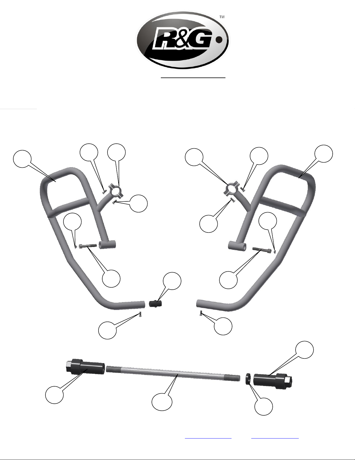
•Remove the original engine bolt as shown in picture 3 (you may have to use the new engine bar (item 10) with a
soft mallet to carefully knock the original bolt out).
Off side (right side as you sit on bike)
•Place the small spacer (item 9) onto the new engine bar (item 10), then engage either of the extensions (item 8)
onto the thread as shown in picture 4 (please ensure it is engaged by approximately 20mm).
•Use this assembly to replace the original engine bolt as shown in picture 4.
Near side (left side as you sit on bike)
•Engage and tighten the remaining extension (item 8) as shown in picture 5.
•Place the connecting bar (item 7) into the end of the left-hand side assembly (item 1) and use one of the M6
button head bolts (item 3) to secure in position (do not fully tighten at this stage) as shown in picture 6.
•Offer the left-hand side assembly into position as shown in picture 7 and secure in position using one of the M10
bolts (item 6) as shown in picture 8 (do not fully tighten at this stage).
•Position one of the tube clamps (item 2) onto the upper trellis tube and secure using two of the M6 bolts (item 3)
as shown in picture 9 (do not fully tighten at this stage).
Off side (right side as you sit on bike)
•Offer the right-hand side assembly (item 4) into position as shown in picture 10 ensuring it locates over the
exposed end of the connecting bar as shown in picture 11 and secure in position using the remaining M10 bolt
(item 6) as shown in picture 12 (do not fully tighten at this stage).
•Position the remaining tube clamp (item 2) onto the upper trellis tube and secure using two of the M6 bolts (item
3) as shown in pictures 13 and 14 (do not fully tighten at this stage).
•Use the remaining M6 bolt (item 3) to secure the connecting bar as shown in picture 15.
•Tighten all bolts on both sides and fit the two flat caps (item 5) as shown in picture 16.
ISSUE 1 28/03/2018 (NSY)
CONSUMER NOTICE
The catalogue description and any exhibition of samples are only broad indications of the Products and R&G may make design changes which do not
diminish their performance or visual appeal and supplying them in such state shall conform to the order. The Buyer acknowledges no representation or
warranty (other than as to title) has been given or will apply to the Products other than those in R&G’s order or confirmation and the Buyer confirms it
has chosen the Products as being of merchantable quality and suitable for its particular purposes. Where R&G fits the Products or undertakes other
services it shall exercise reasonable skill and care and rectify any fault free of charge unless the workmanship has been disturbed. The Buyer is
responsible for ensuring that the warranty on the motorcycle is not affected by the fitting of the Products. On return of any defective Products R&G
shall at its option either supply a replacement or refund the purchase money but shall not be liable if the Products have been modified or used or
maintained otherwise than in accordance with R&G’s or manufacturer’s instructions and good engineering practice or if the defect arises from accident
or neglect. Other than identified above and subject to R&G not limiting its liability for causing death and personal injury, it shall not be liable for
indirect or consequential loss and otherwise its liability shall be limited to the amounts paid by the Buyer for the Products or the fitting or service
concerned. These terms do not affect the Buyer’s statutory rights.
R&G RACING RETURNS POLICY (NON-FAULTY GOODS)
Returns must be pre-authorised (if not pre-authorised the return will be rejected). Goods may only be returned direct to us if they were purchased direct
from us (customer must prove if necessary). Otherwise to be returned to original vendor. Goods must be in re-sellable condition, in the opinion of R&G
Racing. All returns are subject to a 25% restocking and handling fee (25% of the gross value exc. P&P –at the prevailing price at time of purchase). The
customer must pay any and all carriage charges. No returns of discontinued products, unless within 14 days of purchase. This policy does not affect your
statutory rights and does not refer to faulty goods.

AB0026
R&G
Unit 1, Shelley’s Lane, East Worldham, Alton, Hampshire, GU34 3AQ
Tel: +44 (0)1420 89007 Fax: +44 (0)1420 87301 www.rg-racing.com Email: info@rg-racing.com
Page | 7
NOTICE DE MONTAGE POUR AB0026BK BARRES AVENTURE
DUCATI MULTISTRADA 1200 2015-/ 950 2017-/ 1260 2018-
Le kit contient les articles exposés ci-dessous, vérifier que toutes les pièces soient présentes avant de
procéder au montage.
La façon dont le kit est emballé ne correspond pas forcément à la façon de monter les pièces sur la moto.
Notez que si les kits sont emballés avec des rondelles en caoutchouc servant à tenir les
composants, ces rondelles doivent être jetées
LES PARTIES PRESENTEES PEUVENT ETRE UNIQUEMENT REPRESENTATIVES (POUR LA
CLARTE DES INSTRUCTIONS UNIQUEMENT)
Notice disponible au téléchargement sur www.rg-racing.com
DU FAIT DES RISQUES POTENTIELS ENGENDRES PAR L’INSTALLATION DE NOS PROTECTIONS,NOUS RECOMMANDONS TOUJOURS QUE LE MONTAGE
SOIT EFFECTUEPAR UN DE NOS REVENDEURS OFFICIELS OU UN MECANICIEN QUALIFIE.
VALEURS DE SERRAGE RECOMMANDEES
M4 BOULON =8NM
M5 BOULON =12NM
M6 BOULON =15NM
M8 BOULON =20NM
M10 BOULON =40NM
OUTILS REQUIS
•Clé à cliquet + douilles de 15 et 20mm.
•Clés Allen 4 et 8mm.
•Clé dynamométrique (à 40Nm).

AB0026
R&G
Unit 1, Shelley’s Lane, East Worldham, Alton, Hampshire, GU34 3AQ
Tel: +44 (0)1420 89007 Fax: +44 (0)1420 87301 www.rg-racing.com Email: info@rg-racing.com
Page | 8
Le kit doit contenir:
•1x Assemblage de Barre Aventure côté gauche.
•1x Assemblage de Barre Aventure côté droit.
•2x Colliers de serrage.
•1x Barre de connexion.
•1x Axe moteur de remplacement (EB052=M12x265mm de long).
•2x Extensions gauche et droite (E0058).
•1x Entretoise côté droit (S1091=5mm de large).
•2x M10x1.25x60mm Boulons (Supports des 2 côtés).
•6x M6x1x15mm Boulons (Colliers de serrage et boulons d’axe de barre de connexion).
•2x M10 Capuchons (NC0010).
6
1
5
4
3
2
5
6
2
3
8
7
9
10
8
3
3
3
3

AB0026
R&G
Unit 1, Shelley’s Lane, East Worldham, Alton, Hampshire, GU34 3AQ
Tel: +44 (0)1420 89007 Fax: +44 (0)1420 87301 www.rg-racing.com Email: info@rg-racing.com
Page | 9
LÉGENDE
ARTICLE 1 = ASSEMBLAGE DE BARRE AVENTURE CÔTÉ GAUCHE (ASSEMBLAGE SOUDÉ) (x1).
ARTICLE 2 = COLLIER DE SERRAGE (x2).
ARTICLE 3 = M6x1x15mm BOULONS (x6).
ARTICLE 4 = ASSEMBLAGE DE BARRE AVENTURE CÔTÉ DROIT (ASSEMBLAGE SOUDÉ) (x1).
ARTICLE 5 = M10 CAPUCHONS (NC0010) (x2).
ARTICLE 6 = M10x1.25x60mm BOULONS (x4).
ARTICLE 7 = BARRE DE CONNEXION (X1).
ARTICLE 8 = EXTENSIONS FILETÉES (E0058) (x2).
ARTICLE 9 = ENTRETOISE CÔTÉ DROIT (S1091=5mm DE LARGE) (x1).
ARTICLE 10 = M12 AXE MOTEUR (EB052=265mm DE LONG) (x1).
PHOTO 1 PHOTO 2
PHOTO 3 PHOTO 4

AB0026
R&G
Unit 1, Shelley’s Lane, East Worldham, Alton, Hampshire, GU34 3AQ
Tel: +44 (0)1420 89007 Fax: +44 (0)1420 87301 www.rg-racing.com Email: info@rg-racing.com
Page | 12
NOTICE DE MONTAGE
Côté droit (lorsqu’on est assis sur la moto)
•Enlever l’écrou de boulon moteur d’origine, voir photo 1.
Côté gauche (lorsqu’on est assis sur la moto)
•Il est conseillé de tenir le moteur, voir photo 2 pour éviter qu’il bouge.
•Enlever le boulon moteur d’origine, voir photo 3 (vous aurez peut-être besoin d’utiliser le nouvel axe moteur
(article 10) avec un maillet pour tapoter sur le boulon d’origine pour l’extraire).
Côté droit (lorsqu’on est assis sur la moto)
•Placer la petite entretoise (article 9) sur le nouvel axe moteur (article 10), puis engager l’une des extensions
(article 8) sur le filetage, voir photo 4 (veiller à ce qu’il soit engagé à environ 20mm).
•Utiliser cet ensemble pour remplacer le boulon moteur d’origine, voir photo 4.
Côté gauche (lorsqu’on est assis sur la moto)
•Engager et serrer l’extension restante (article 8), voir photo 5.
•Placer la barre de connexion (article 7) dans l’extrémité de l’ensemble du côté gauche (article 1) puis utiliser
un des boulons M6 (article 3) pour fixer la position (Ne pas serrer complètement pour le moment), voir photo
6.
•Monter l’ensemble du côté gauche en position, voir photo 7 puis fixer la position en utilisant un des boulons
M10 (article 6), voir photo 8 (Ne pas serrer complètement pour le moment).
•Positionner un des colliers de serrage (article 2) sur le tube treillis supérieur puis fixer à l’aide des 2 boulons
M6 (article 3), voir photo 9 (Ne pas serrer complètement pour le moment).
Côté droit (lorsqu’on est assis sur la moto)
•Monter l’ensemble du côté droit en position (article 4), voir photo 10 en veillant à ce qu’il se place sur
l’extrémité de la barre de connexion, voir photo 11 puis fixer la position en utilisant le boulon M10 (article
6), voir photo 12 (Ne pas serrer complètement pour le moment).
•Positionner le collier de serrage restant (article 2) sur le tube treillis supérieur puis fixer à l’aide des 2 boulons
M6 (article 3), voir photos 13 et 14 (Ne pas serrer complètement pour le moment).
•Utiliser le boulon M6 restant (article 3) pour fixer la barre de connexion, voir photo 15.
•Serrer tous les boulons des 2 côtés puis insérer les 2 capuchons (article 5), voir photo 16.
ISSUE 1 28/03/2018 (NSY)
CONSUMER NOTICE
The catalogue description and any exhibition of samples are only broad indications of the Products and R&G may make design changes which do not
diminish their performance or visual appeal and supplying them in such state shall conform to the order. The Buyer acknowledges no representation or
warranty (other than as to title) has been given or will apply to the Products other than those in R&G’s order or confirmation and the Buyer confirms it
has chosen the Products as being of merchantable quality and suitable for its particular purposes. Where R&G fits the Products or undertakes other
services it shall exercise reasonable skill and care and rectify any fault free of charge unless the workmanship has been disturbed. The Buyer is
responsible for ensuring that the warranty on the motorcycle is not affected by the fitting of the Products. On return of any defective Products R&G
shall at its option either supply a replacement or refund the purchase money but shall not be liable if the Products have been modified or used or
maintained otherwise than in accordance with R&G’s or manufacturer’s instructions and good engineering practice or if the defect arises from accident
or neglect. Other than identified above and subject to R&G not limiting its liability for causing death and personal injury, it shall not be liable for
indirect or consequential loss and otherwise its liability shall be limited to the amounts paid by the Buyer for the Products or the fitting or service
concerned. These terms do not affect the Buyer’s statutory rights.

AB0026
R&G
Unit 1, Shelley’s Lane, East Worldham, Alton, Hampshire, GU34 3AQ
Tel: +44 (0)1420 89007 Fax: +44 (0)1420 87301 www.rg-racing.com Email: info@rg-racing.com
Page | 13
R&G RACING RETURNS POLICY (NON-FAULTY GOODS)
Returns must be pre-authorised (if not pre-authorised the return will be rejected). Goods may only be returned direct to us if they were purchased direct
from us (customer must prove if necessary). Otherwise to be returned to original vendor. Goods must be in re-sellable condition, in the opinion of R&G
Racing. All returns are subject to a 25% restocking and handling fee (25% of the gross value exc. P&P –at the prevailing price at time of purchase). The
customer must pay any and all carriage charges. No returns of discontinued products, unless within 14 days of purchase. This policy does not affect your
statutory rights and does not refer to faulty goods.

AB0026
R&G
Unit 1, Shelley’s Lane, East Worldham, Alton, Hampshire, GU34 3AQ
Tel: +44 (0)1420 89007 Fax: +44 (0)1420 87301 www.rg-racing.com Email: info@rg-racing.com
Page | 14
MONTAGEANLEITUNG FÜR AB0026BK ADVENTURE STURZBÜGEL
DUCATI MULTISTRADA 1200 2015-/ 950 2017-/ 1260 2018-
ALLE KIT-TEILE SIND UNTEN ABGEBILDET UND GEKENNZEICHNET. BEVOR SIE MIT DER MONTAGE BEGINNEN,
ÜBERPRÜFEN SIE, DASS ALLE TEILE VORHANDEN SIND.
Hinweis: Die Verpackung der Teile stellt nicht die Reihenfolge der Montage dar.
Hinweis für Kits mit Plastikunterlegscheiben an den Schrauben –Diese Plastikunterlegscheiben werden nicht für den Einbau benötigt!
DIE UNTEN ABGEBILDETEN TEILE DIENEN LEDIGLICH ZUR ERKLÄRUNG
Eine digitale Version dieser Montageanleitung kann auf folgender Seite heruntergeladen werden:
www.rg-racing.com
UM EIN EVENTUELLES ÜBERDREHEN ODER VERKANTEN DER SCHRAUBEN ZU VERMEIDEN,EMPFEHLEN WIR IMMER,UNSERE KITS VON EINEM
UNSERER OFFIZIELLEN HÄNDLER ODER EINEM QUALIFIZIERTEN ZWEIRADMECHANIKER MONTIEREN ZU LASSEN.
ALLGEMEINE ANZUGSDREHMOMENTE:
M4 SCHRAUBE = 8Nm
M5 SCHRAUBE = 12Nm
M6 SCHRAUBE = 15Nm
M8 SCHRAUBE = 20Nm
M10 SCHRAUBE = 40Nm
SIE BENÖTIGEN FOLGENDES WERZEUG
•Steckschlüsselsatz inkl. 15 und 20mm A/F Steckschlüssel
•Satz Inbusschlüssel inkl. 4 und 8mm A/F Inbusschlüssel
•Drehmomentschlüssel (bis 40Nm)

AB0026
R&G
Unit 1, Shelley’s Lane, East Worldham, Alton, Hampshire, GU34 3AQ
Tel: +44 (0)1420 89007 Fax: +44 (0)1420 87301 www.rg-racing.com Email: info@rg-racing.com
Page | 15
Inhalt des Kits:
•1x Adventure Sturzbügel, linke Seite
•1x Adventure Sturzbügel, rechte Seite
•2x Schlauchklemmen
•1x Verbindungsstück
•1x Austausch Verbindungsstange (EB052=M12x265mm Länge)
•2x linke und rechte Verlängerungen (E0058)
•1x Distanzhalter –rechte Seite (S1091=5mm breit)
•2x M10x1,25x60mm Linsenkopfschrauben (montiert beide Seiten)
•6x M6x1x15mm Inbusschrauben (Schlauchklemmen und Verbindungsstange- Schrauben)
•2x M10 Kappen für die Linsenkopfschrauben (NC0010)
6
1
5
4
3
2
5
6
2
3
8
7
9
10
8
3
3
3
3

AB0026
R&G
Unit 1, Shelley’s Lane, East Worldham, Alton, Hampshire, GU34 3AQ
Tel: +44 (0)1420 89007 Fax: +44 (0)1420 87301 www.rg-racing.com Email: info@rg-racing.com
Page | 16
LIEFERUMFANG
ARTIKEL 1 = ADVENTURE STURZBÜGEL LINKE SEITE (ZUSAMMENGESCHWEISST) (x1)
ARTIKEL 2 = SCHLAUCHKLEMME (x2)
ARTIKEL 3 = M6x1x15mm INBUSSCHRAUBEN (x6)
ARTIKEL 4 = ADVENTURE STURZBÜGEL RECHTE SEITE (ZUSAMMENGESCHWEISST) (x1)
ARTIKEL 5 = M10 KAPPEN FÜR DIE SCHRAUBEN (NC0010) (x2)
ARTIKEL 6 = M10x1,25x60mm LINSENKOPFSCHRAUBE (x4)
ARTIKEL 7 = VERBINDUNGSSTÜCK (X1)
ARTIKEL 8 = VERLÄNGERUNGEN MIT GEWINDE (E0058) (x2).
ARTIKEL 9 = DISTANZHALTER –RECHTE SEITE (S1091=5mm BREIT) (x1)
ARTIKEL 10 = M12 VERBINDUNGSSTANGE (EB052=265mm LÄNGE) (x1)
ABBILDUNG 1 ABBILDUNG 2
ABBILDUNG 3 ABBILDUNG 4

AB0026
R&G
Unit 1, Shelley’s Lane, East Worldham, Alton, Hampshire, GU34 3AQ
Tel: +44 (0)1420 89007 Fax: +44 (0)1420 87301 www.rg-racing.com Email: info@rg-racing.com
Page | 19
MONTAGEANLEITUNG
Rechte Seite (in Fahrtrichtung)
•Lösen und entfernen Sie die original Motorschraube-Mutter, die in Abbildung 1 gekennzeichnet ist.
Linke Seite (in Fahrtrichtung)
•Es empfiehlt sich, den Motor zu diesem Zeitpunkt zu stützen (siehe Abbildung 2), somit wird verhindert, dass
der Motor sich während der Montage bewegen kann.
•Entfernen Sie die original Motorschraube, wie in Abbildung 3 abgebildet (eventuell müssen Sie die neue
Verbindungsstange (Artikel 10) und einen Schonhammer benutzen, um die original Schraube rauszuschieben).
Rechte Seite (in Fahrtrichtung)
•Den kleinen Distanzhalter (Artikel 9) an der neuen Verbindungsstange (Artikel 10) anbringen, dann eine der
Verlängerungen (Artikel 8) am Gewinde montieren –siehe Abbildung 4 (bitte darauf achten, dass sie bei ca.
20mm eingerastet ist).
•Benutzen Sie diese Einheit, um die original Motorschraube zu ersetzen –siehe Abbildung 4.
Linke Seite (in Fahrtrichtung)
•Die übrige Verlängerung (Artikel 8) einrasten und befestigen wie in Abbildung 5 abgebildet.
•Das Verbindungsstück (Artikel 7) am Ende der Einheit für die linke Seite (Artikel 1) anbringen und mit einer der
M6 Inbusschrauben (Artikel 3) befestigen, wie in Abbildung 6 abgebildet (noch nicht komplett festziehen).
•Die Einheit für die linke Seite in Position bringen wie in Abbildung 7 abgebildet und mit einer der M10
Schrauben (Artikel 6) in Position befestigen –siehe Abbildung 8 (noch nicht komplett festziehen).
•Eine der Schlauchklemmen (Artikel 2) am oberen Trellis-Gitterrohr positionieren und mit einer der zwei M6
Schrauben (Artikel 3) fixieren –siehe Abbildung 9 (noch nicht komplett festziehen).
Rechte Seite (in Fahrtrichtung)
•Die Einheit für die rechte Seite (Artikel 4) anbringen wie in Abbildung 10 abgebildet –bitte darauf achten, dass
sie am hervorstehenden Ende des Verbindungsstücks positioniert ist –siehe Abbildung 11 –und benutzen Sie
die übrige M10 Schraube (Artikel 6), um sie zu befestigen wie in Abbildung 12 abgebildet (noch nicht komplett
festziehen).
•Positionieren Sie die übrige Schlauchklemme (Artikel 2) am oberen Trellis-Gitterrohr und befestigen Sie sie mit
zwei M6 Schrauben (Artikel 3) –siehe Abbildungen 13 und 14 (noch nicht komplett festziehen).
•Benutzen Sie die übrigen M6 Schraube (Artikel 3), um das Verbindungsstück zu befestigen –siehe Abbildung
15.
•Ziehen Sie alle Schrauben an beiden Seiten fest und montieren Sie die zwei Kappen für die Schrauben (Artikel
5), wie in Abbildung 16 abgebildet.
AUSGABE 1 28/03/2018 (NSY)
CONSUMER NOTICE
The catalogue description and any exhibition of samples are only broad indications of the Products and R&G may make design changes which do not diminish their performance or visual appeal and
supplying them in such state shall conform to the order. The Buyer acknowledges no representation or warranty (other than as to title) has been given or will apply to the Products other than those in
R&G’s order or confirmation and the Buyer confirms it has chosen the Products as being of merchantable quality and suitable for its particular purposes. Where R&G fits the Products or undertakes other
services it shall exercise reasonable skill and care and rectify any fault free of charge unless the workmanship has been disturbed. The Buyer is responsible for ensuring that the warranty on the
motorcycle is not affected by the fitting of the Products. On return of any defective Products R&G shall at its option either supply a replacement or refund the purchase money but shall not be liable if the
Products have been modified or used or maintained otherwise than in accordance with R&G’s or manufacturer’s instructions and good engineering practice or if the defect arises from accident or neglect.
Other than identified above and subject to R&G not limiting its liability for causing death and personal injury, it shall not be liable for indirect or consequential loss and otherwise its liability shall be
limited to the amounts paid by the Buyer for the Products or the fitting or service concerned. These terms do not affect the Buyer’s statutory rights.
R&G RACING RETURNS POLICY (NON-FAULTY GOODS)
Returns must be pre-authorised (if not pre-authorised the return will be rejected). Goods may only be returned direct to us if they were purchased direct from us (customer must prove if necessary).
Otherwise to be returned to original vendor. Goods must be in re-sellable condition, in the opinion of R&G Racing. All returns are subject to a 25% restocking and handling fee (25% of the gross value
exc. P&P –at the prevailing price at time of purchase). The customer must pay any and all carriage charges. No returns of discontinued products, unless within 14 days of purchase. This policy does not
affect your statutory rights and does not refer to faulty goods.
Table of contents
Languages:
Other R&G Motorcycle Accessories manuals
Popular Motorcycle Accessories manuals by other brands

LSK
LSK FuelGaugePro FGP-SENSOR installation manual

Petzl
Petzl VERTEX VENT manual

RS Motorcycle Solutions
RS Motorcycle Solutions SC969 quick start guide

HealTech Electronics
HealTech Electronics iLogger easy Supplementary manual

DUCATI Performance
DUCATI Performance 96981341AA installation instructions

Athena
Athena S410000500001 Assembling

Suzuki
Suzuki 990D0-17K34-000 installation instructions

hepco & becker
hepco & becker 650652 00 01 Mounting instructions

Suzuki
Suzuki 99000-99074-88N installation instructions

ConforTeck
ConforTeck DUO user manual

Petzl
Petzl Vertex Best Duo Instructions for use

hepco & becker
hepco & becker 8007601 00 01 manual