Reer VISION VX Quick start guide

PHOTOELECTRIC
SAFETY BARRIER
VISION VX
I
IN
NS
ST
TA
AL
LL
LA
AZ
ZI
IO
ON
NE
E,
,
U
US
SO
O
E
E
M
MA
AN
NU
UT
TE
EN
NZ
ZI
IO
ON
NE
E
I
IN
NS
ST
TA
AL
LL
LA
AT
TI
IO
ON
N,
,
U
US
SE
E
A
AN
ND
D
M
MA
AI
IN
NT
TE
EN
NA
AN
NC
CE
E
I
IN
NS
ST
TA
AL
LL
LA
AT
TI
IO
ON
N,
,
U
UT
TI
IL
LI
IS
SA
AT
TI
IO
ON
N
E
ET
T
M
MA
AI
IN
NT
TE
EN
NA
AN
NC
CE
E
I
IN
NS
ST
TA
AL
LL
LA
AT
TI
IO
ON
N,
,
B
BE
ED
DI
IE
EN
NU
UN
NG
G
U
UN
ND
D
W
WA
AR
RT
TU
UN
NG
G
I
IN
NS
ST
TA
AL
LA
AC
CI
IÓ
ÓN
N,
,
U
US
SO
O
Y
Y
M
MA
AN
NT
TE
EN
NI
IM
MI
IE
EN
NT
TO
O
www.reer.it

8540571 - 25/08/2016 - Rev.15
1
PHOTOELECTRIC
SAFETY
BARRIER
VISION VX
INSTALLATION USE AND MAINTENANCE
INDICE
INTRODUCTION...................................................................................................................2
NEW SAFETY PARAMETERS FOR TYPE 2 BARRIERS AND MANDATORY LABELLING.......3
OPERATION .........................................................................................................................4
INSTALLATION.....................................................................................................................5
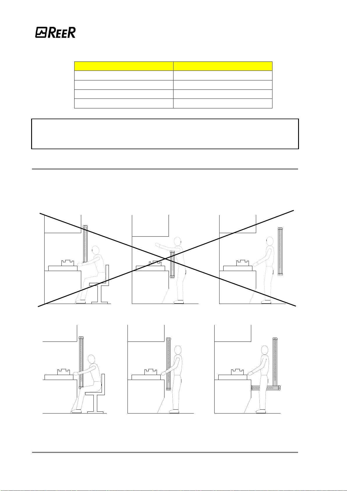
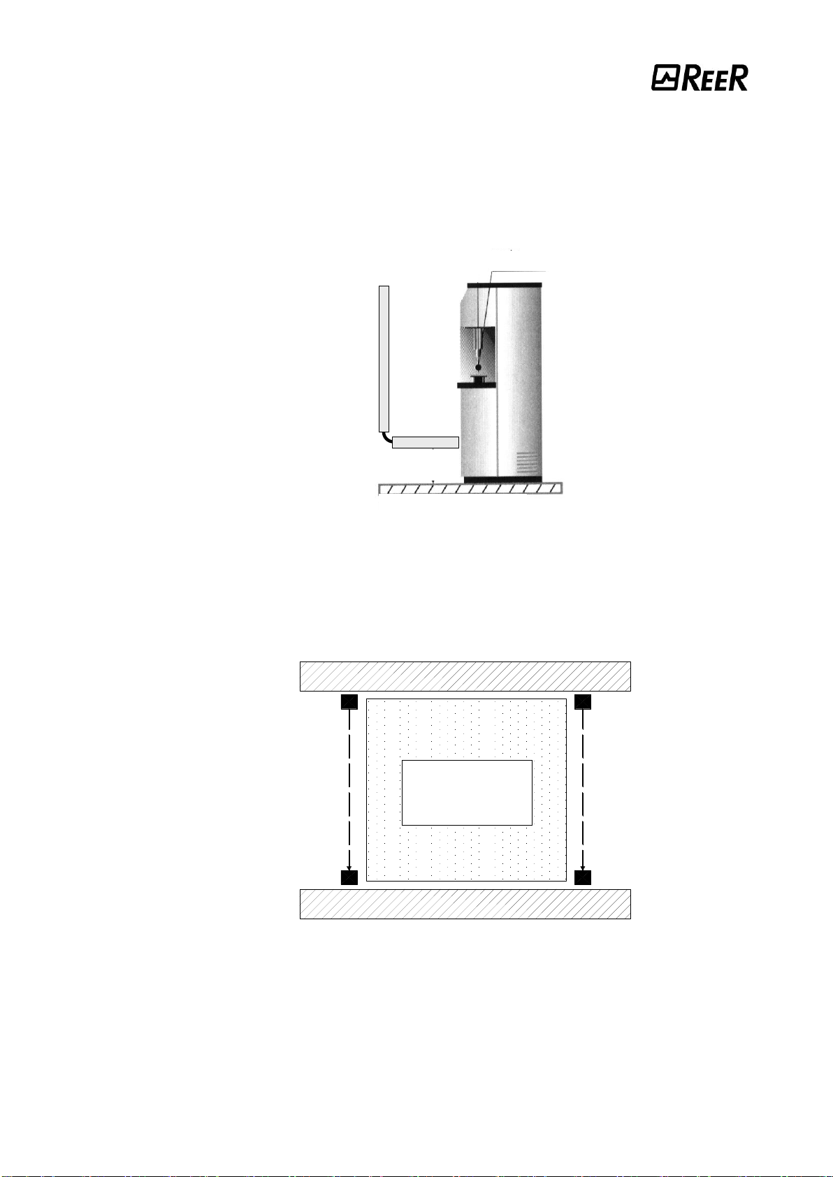
POSITION......................................................................................................................................6
MASTER/SLAVE POSITIONING...................................................................................................6
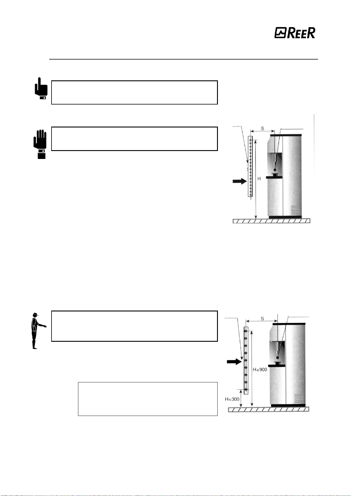
SAFETY DISTANCE CALCULATION............................................................................................8
VERTICAL POSITION OF THE BARRIER....................................................................................9
HORIZONTAL POSITION OF THE BARRIER ........................................................................... 10
ELECTRICAL CONNECTIONS .................................................................................................. 11
EMITTER CONNECTIONS......................................................................................................... 12
RECEIVER CONNECTIONS...................................................................................................... 12
WARNINGS REGARDING THE CONNECTION CABLES......................................................... 13
CONFIGURATION AND OPERATION MODES......................................................................... 19
K1/K2 EXTERNAL CONTACTORS CONNECTION................................................................... 20
MULTIPLE SYSTEMS ................................................................................................................ 20
USE OF DEFLECTION MIRRORS............................................................................................. 21
DISTANCE BETWEEN REFLECTING SURFACES .................................................................. 22
MECHANICAL ASSEMBLY AND OPTICAL ALIGNMENT......................................................... 23
OPERATION AND TECHNICAL DATA................................................................................24
SIGNALS..................................................................................................................................... 24
TEST FUNCTION ....................................................................................................................... 26
OUTPUT STATUS ...................................................................................................................... 27
TECHNICAL SPECIFICATIONS................................................................................................. 28
DIMENSIONS......................................................................................................................30
CHECKOUTS AND MAINTENANCE...................................................................................32
VERIFICATION OF BARRIER EFFICIENCY ............................................................................. 32
TROUBLESHOOTING................................................................................................................ 33
SPARE PARTS....................................................................................................................36
GUARANTEE ......................................................................................................................37

2 8540571 - 25/08/2016 - Rev.15
This symbol stands by a very important warning concerning the safety of persons.
Its non-observance can cause a very serious risk for the exposed personnel.
INTRODUCTION
The VISION VX photoelectric barrier is a multi-beam optoelectronic safety system. It belongs
to the family of Type 2 electrosensitive devices for the protection of personnel exposed to
risks arising from the use of hazardous machinery or plant, according to standards
IEC 61496-1,2 and EN 61496-1.
VISION VX is available in two different versions :
1. VISION VX (STANDARD)
Type 2 photoelectric barrier composed of Emitter and Receiver with integration of additional
functions, such as the external contactors feedback control and the manual/automatic
operation management.
2. VISION VX MASTER/SLAVE
Type 2 (STANDARD) photoelectric barrier composed of two TX/RX couples (connected in
series). The first of the couples is the MASTER barrier (with additional functions) and the
second is the SLAVE barrier.
A diagnostic display available on Emitter and Receiver provides the necessary information
for a correct use of the device and the evaluation of the possible operation defects.
VISION VX is ideal for the protection of :
Machinery for product handling such as conveyors, palletizing, collating machines;
packaging and wrapping devices; automated assembly lines; automated warehousing.
If necessary, for any safety-related problems contact the competent safety
authorities or industrial associations in the country of use.
For applications in the food industry, please contact the manufacturer to ensure that
the barrier contains materials that are compatible with the chemical agents utilized.
The protective function of the optoelectronic devices is not effective in the following cases:
If the machine stopping control cannot be actuated electrically and it is not possible
to stop all dangerous machine movements immediately and at any time during the
operating cycle.
If the machine generates dangerous situations due to material being expelled or
falling from overhead.

8540571 - 25/08/2016 - Rev.15 3
NEW SAFETY PARAMETERS FORTYPE 2BARRIERS AND MANDATORY LABELLING
With the publication of Edition 3 of the harmonized EN 61496-1 standard it is no longer
possible to use a Type 2 safety light barrier for safety functions assessed as
SIL 2 / PL d.
If a safety level of SIL 2 / PL d (or higher) is required and it is nevertheless intended to
use a safety light barrier, then it will be necessary to use a Type 4 safety light barrier.
This regulatory requirement derives from the fact that the reduction of risk that can be
obtained via a photoelectric safety barrier is not only a function of the safety level of its
electronic parts, but is also determined by its systematic capabilities (for example:
environmental influences, EMC, optical performance and detection principle).
The systematic capability of a Type 2 photoelectric barrier may in fact not be sufficient
to ensure adequate risk reduction for SIL 2 / PL d applications.
The standard also establishes that the labelling of Type 2 safety barriers must indicate
such limitation to SIL 1 / PL c.
The PFHd values declared for the electronic control part of the device, on the other
hand, are not limited and therefore it is possible to use the PFHd value provided by the
manufacturer of the device in the global assessment of the safety function, even if it
exceeds the SIL 1 / PLc range.

4 8540571 - 25/08/2016 - Rev.15
OPERATION
If the protected area is clear, the two outputs on the Receiver are active and enable the
machine to which they are connected to operate normally.
Each time that an object bigger than or equal in size to the resolution of the system
intercepts the optical path of one or more beams, the Receiver deactivates the outputs.
This condition enables hazardous machine movements to be stopped (by means of an
adequate machine emergency stop circuit).
The resolution is the minimum dimensions that an object must have so that, on
crossing the protected area, it will certainly intercept at least one of the optical
beams generated by the barrier (Figure 1).
Figure 1
The resolution is constant irrespectively of work conditions, as it only depends on the
geometric characteristics of the lenses and the distance between the centres of two adjacent
lenses.
The height of the protected area is the height that is actually protected by the safety
barrier. If the latter is placed horizontally, this value refers to the depth of the protected area.
The working range is the maximum operative distance that can exist between the Emitter
and the Receiver.
VISION VX is available with the following resolutions:
–20 mm (protected height from 150 mm to 1800 mm)
PROTECTION OF FINGERS
–30 mm (protected height from 150 mm to 1800 mm)
PROTECTION OF HANDS
–40 mm (protected height from 300 mm to 1800 mm)
PROTECTION OF HANDS
–50 mm and 90 mm (protected height from 300 mm to 1800 mm)
PROTECTION OF ARMS AND LEGS
VISION VX is available also in the Multibeam and Long Range configuration with the
following lens pitch:
–500mm (2 beams), 400mm (3 beams), 300mm (4 beams).
PROTECTION OF BODY
P = Pitch between two lenses
D = Diameter of one lens
R = Resolution = P+D

8540571 - 25/08/2016 - Rev.15 5
INSTALLATION
Before installing the VISION VX safety system, make sure that:
The safety system is only used as a stopping device and not as a machine control
device.
The machine control can be actuated electrically.
All dangerous machine movements can be interrupted immediately. In particular, the
machine stopping times must be known and, if necessary, measured.
The machine does not generate dangerous situations due to materials projecting or
falling from overhead; if that is not the case, additional mechanical guards must be
installed.
The minimum dimensions of the object that must be intercepted are greater than or
equal to the resolution of the specific model.
Knowledge of the shape and dimensions of the dangerous area enables the width and height
of the relative access area to be calculated.
Compare these dimensions with the maximum working range and the height of the
protected area in relation to the specific model.
The general instructions set out below must be taken into consideration before placing the
safety device in position.
Make sure that the temperature of the environment in which the system is to be
installed is compatible with the temperature parameters contained in the technical
data sheet.
Do not install the Emitter and Receiver close to bright or high-intensity flashing light
sources.
Certain environmental conditions may affect the monitoring capacity of the
photoelectric devices. In order to assure correct operation of equipment in places
that may be subject to fog, rain, smoke or dust, the appropriate correction factors Cf
should be applied to the maximum working range values. In these cases:
where Pu and Pm are, respectively, the working and maximum range in meters.
Pu = Pm x Cf

6 8540571 - 25/08/2016 - Rev.15
The recommended Cf factors are shown in the table below:
ENVIRONMENTAL CONDITION
CORRECTION FACTOR Cf
Fog
0.25
Steam
0.50
Dust
0.50
Dense fumes
0.25
If the device is installed in places that are subject to sudden changes in temperature,
the appropriate precautions must be taken in order to prevent the formation of
condensation on the lenses, which could have an adverse effect on monitoring.
POSITION
The position of the VXEEmitter and the VXRReceiver must prevent access to the danger
zone from above, below and from the sides, unless at least one of the optical beams has
been intercepted. Some useful information regarding the correct position of the barrier is
shown in the figure below.
Incorrect positioning of barrier
Correct positioning of barrier
Figure 2
MASTER/SLAVE POSITIONING

8540571 - 25/08/2016 - Rev.15 7
In addition to the standard VISION models, VISION VX is available in the MASTER/SLAVE
configuration. Such configuration is made of two pairs of light curtains, where the two
emitters and the two receivers are respectively connected in series.
The most common application is shown in Figure 3: the horizontal light curtain (A) has been
installed to detect the presence of a person between the vertical light curtain (B) and the
dangerous machine at system power-up or restart.
Figure 3
The length of the connection cable between the master and the slave can be up to 50 m.
This makes it possible to install two light curtains - one at the front and the other at the rear
of the machine –with just one connection to the power and control circuits of the machine.
PROTEZIONE MECCANICA
MACCHINA
PERICOLOSA
TX1 TX2
RX1 RX2
BARRIERA
MASTER BARRIERA
SLAVE
Figure 4
MECHANICAL GUARD
MASTER
BARRIER
SLAVE
BARRIER
DANGEROUS
MACHINE
MECHANICAL GUARD
Barrier B
(SLAVE)
Barrier A
(MASTER)
Reference plane
Point of danger

8 8540571 - 25/08/2016 - Rev.15
SAFETY DISTANCE CALCULATION
The barrier must be installed at a distance that is greater than or equal to the minimum
safety distance S, so that a dangerous point can only be reached after all hazardous
machine movements have stopped (Figure 5).
According to European standard EN999, the minimum safety distance Smust be calculated
using the following formula:
S = K (t1+ t2) + C
where:
S
minimum safety distance
mm
K
approach speed of object to the dangerous area
mm/sec
t1
response time of the safety barrier in seconds
sec
t2
machine response time, in seconds, meaning the time
required for the machine to interrupt the dangerous movement
following transmission of the stop signal
sec
c
additional distance
mm
The non-observance of the correct safety distance reduces or cancels the protective
action of the light curtain.
If the position of the barrier does not prevent the operator from having access to the
dangerous area without being detected, additional mechanical guards must be
installed to complete the system.
“S”=Safety distance
Figure 5
HAZARDOUS
MACHINE
S

8540571 - 25/08/2016 - Rev.15 9
VERTICAL POSITION OF THE BARRIER
20 mm resolution models.
These models are suitable for the protection of
fingers.
30 mm and 40 mm resolution models.
These models are suitable for the protection of
hands.
The minimum safety distance Sis calculated
according to the following formula:
S = 2000(t1+ t2) + 8(D-14)
(D=resolution)
This formula is valid for distances Sbetween 100
and 500 mm. If this formula results in Sbeing
greater than 500 mm, the distance can be reduced
to a minimum of 500 mm by means of the following
formula:
S = 1600(t1+ t2) + 8(D-14)
If, due to the specific configuration of the machine,
the dangerous area can be accessed from above,
the highest beam of the barrier must be at a height
Hof at least 1800 mm from the base Gof the
machine.
Figure 6
50 mm and 90 mm resolution models.
These models are suitable for the protection of
arms or legs and must not be used to protect
fingers or hands.
The minimum safety distance Sis calculated
according to the following formula:
S = 1600(t1+ t2) + 850
The height Hof the highest beam from the
base Gmust never be less than 900 mm,
while the height of the lowest beam P
must never be more than 300 mm.
Figure 7
safety barrier
point of
danger
direction
of
approach
reference plane
safety barrier
point of
danger
direction
of
approach
reference plane

10 8540571 - 25/08/2016 - Rev.15
Multibeam Models.
These models are suitable for the protection of
the entire body and must not be used to protect
arms or legs.
The minimum safety distance Sis calculated
according to the following formula:
S = 1600 (t1+ t2) + 850
The reccomended height Hfrom the base
(G) must be the following:
Figure 8
MODEL
BEAMS
Reccomended Height H (mm)
VX 2B
VX 3B
VX 4B
2
3
4
400 –900
300 –700 –1100
300 –600 –900 - 1200
HORIZONTAL POSITION OF THE BARRIER
When the object’s direction of approach is parallel to
the floor of the protected area, the barrier must be
installed so that the distance between the outer limit
of the dangerous area and the most external optical
beam is greater than or equal to the minimum safety
distance Scalculated as follows:
S = 1600(t1+ t2) + 1200 –0.4H
where His the height of the protected surface from
the base of the machine;
H = 15(D-50)
(D=resolution)
In this case, Hmust always be less than 1 meter.
Figure 9
safety barrier
point of
danger
direction
of approach
reference plane
safety
barrier
point of
danger
direction
of
approach
reference plane

8540571 - 25/08/2016 - Rev.15 11
ELECTRICAL CONNECTIONS
WARNINGS
Before making the electrical connections, make sure that the supply voltage complies with
that specified in the technical data sheet.
Emitter and Receiver units must be supplied with 24Vdc±20% power.
The external power supply must comply with the standard EN 60204-1.
The electrical connections must be made according to the diagrams in this manual. In
particular, do not connect other devices to the connectors of the Emitter and Receiver.
For reliability of operation, when a diode jumper supply unit is used, its output capacity must
be at least 2000µF for each absorbed A.
MASTER/SLAVE CONNECTORS LOCATION
Figure 10
SLAVE CONNECTOR
SECONDARY MASTER CONNECTOR
PRIMARY
MASTER
CONNECTOR

12 8540571 - 25/08/2016 - Rev.15
EMITTER CONNECTIONS
VX/VXM/VXS - 5 poles M12 connector (power-supply).
VXM (Master models) - 5 poles M12 Secondary connector.
PIN
COLOR
NAME
TYPE
DESCRIPTION
FUNCTIONING
1
Brown
24VDC
INPUT
+24 VDC power supply
-
3
Blue
0VDC
0 VDC power supply
-
5
Grey
PE
Ground connection
-
2
White
RANGE0*
Barrier configuration
According the normative
EN61131-2 (ref. Table 2)
4
Black
RANGE1*
* OUTPUT only on MASTER Secondary connector
Table 1
TEST and RANGE SELECTION
PIN 4
PIN 2
FUNCTIONING
24VDC
0VDC
HIGH range (1÷18m)
(3÷18 on Master/Slave) (18÷60 on Long Range)
0VDC
24VDC
LOW range (0 - 6m) (10÷22 on Long Range)
0VDC
0VDC
Emitter in test mode
24VDC
24VDC
Selection error
Table 2
RECEIVER CONNECTIONS
VX - 8 poles M12 connector.
VXM (Master models) - 8 poles M12 Primary connector.
PIN
COLOR
NAME
TYPE
DESCRIPTION
FUNCTIONING
2
Brown
24VDC
-
+24 VDC power supply
-
7
Blue
0VDC
-
0 VDC power supply
-
8
Red
PE
-
Ground connection
-
1
White
OSSD1
OUTPUT
Safety static outputs
PNP active high
3
Green
OSSD2
OUTPUT
5
Grey
SEL_A
INPUT
Barrier configuration
According the normative EN61131-2
(ref. Par. "Configuration and operation
modes" page 19)
6
Pink
SEL_B
INPUT
4
Yellow
K1_K2
INPUT
External contactors
Feedback
Table 3

8540571 - 25/08/2016 - Rev.15 13
VXS (Slave models) - 5 poles M12 connector (power-supply)
PIN
COLOR
NAME
TYPE
DESCRIPTION
FUNCTIONING
1
Brown
24VDC
-
+24 VDC power supply
-
3
Blue
0VDC
-
0 VDC power supply
-
5
Grey
PE
-
Ground connection
-
2
White
OSSD1
OUTPUT
Safety static outputs
PNP active high
4
Black
OSSD2
OUTPUT
Table 4
VXM (Master models) - 5 poles M12 Secondary connector.
PIN
COLOR
NAME
TYPE
DESCRIPTION
FUNCTIONING
1
Brown
24VDC
-
+24 VDC power supply
-
3
Blue
0VDC
-
0 VDC power supply
-
5
Grey
PE
-
Ground connection
-
2
White
SLAVE1
INPUT
Slave OSSD outputs
readout
According the normative
EN61131-2
(PNP active high)
4
Black
SLAVE2
INPUT
Table 5
WARNINGS REGARDING THE CONNECTION CABLES
For connections over 50 m long, use cables with a cross-section area
of 1 mm2.
The power supply to the barrier should be kept separate from that to other
electric power equipment (electric motors, inverters, frequency converters) or
other sources of disturbance.
Connect the Emitter and the Receiver to the ground outlet.
The connection cables must follow a different route to that of the other power
cables.

14 8540571 - 25/08/2016 - Rev.15
Example of MASTER-SLAVE connection in
MANUAL mode without external contactors K1-K2
Figure 11
In order to assure a correct barrier operation, it is necessary to
connect the pins 2 and 4 of the Emitter according to table 2 (page 11) and
to the "TEST FUNCTION" paragraph of page 25.
(Ref. Table 2
Page 11)

8540571 - 25/08/2016 - Rev.15 15
Example of MASTER-SLAVE connection in
MANUAL mode with external contactors K1-K2
Figure 12
In order to assure a correct barrier operation, it is necessary to
connect the pins 2 and 4 of the Emitter according to table 2 (page 11) and
to the "TEST FUNCTION" paragraph of page 25.
(Ref. Table 2
Page 11)

16 8540571 - 25/08/2016 - Rev.15
Example of MASTER-SLAVE connection in
AUTOMATIC mode without external contactors K1-K2
Figure 13
In order to assure a correct barrier operation, it is necessary to
connect the pins 2 and 4 of the Emitter according to table 2 (page 11) and
to the "TEST FUNCTION" paragraph of page 25.
Example of MASTER-SLAVE connection in
AUTOMATIC mode with external contactors K1-K2
(Ref. Table 2
Page 11)

18 8540571 - 25/08/2016 - Rev.15
Example of connection in MANUAL mode
with external contactors K1-K2
Figure 15
Example of connection in AUTOMATIC mode
with external contactors K1-K2
Figure 16
In order to assure a correct barrier operation, it is necessary to
connect the pins 2 and 4 of the Emitter according to table 2 (page 11) and
to the "TEST FUNCTION" paragraph of page 25.
(Ref. Table 2
Page 11)
(Ref. Table 2
Page 11)

8540571 - 25/08/2016 - Rev.15 19
CONFIGURATION AND OPERATION MODES
The VISION VX operation mode is selected realizing appropriate connections on the M12 8
poles of the Receiver (Table 6 and Table 7).
AUTOMATIC MODE
The VISION VX light curtain does not dispose of a start/restart interlock circuit in
automatic mode. In most applications this safety function is necessary. Please
consider the risk-analysis of your application about this matter.
In AUTOMATIC functioning, the two static outputs OSSD1 and OSSD2 follow the status of
the guarded opening.
with the area guarded clear, the outputs will supply +24VDC
with the area occupied they will supply 0VDC.
CONNECTION
OPERATION MODE
SEL_A (PIN 5)
connected to :
OSSD1 (PIN 1)
SEL_B (PIN 6)
connected to :
OSSD2 (PIN 3)
K1_K2 (PIN 4)
connected to :
0VDC
AUTOMATIC without
K1-K2 feedback control
SEL_A (PIN 5)
connected to :
OSSD2 (PIN 3)
SEL_B (PIN 6)
connected to :
OSSD1 (PIN 1)
K1_K2 (PIN 4)
connected to : 24VDC
(through series of contatcts
N.C. of external relays)
AUTOMATIC with
K1-K2 feedback control
Table 6
MANUAL MODE
Use of manual mode (start/restart interlock activated) is compulsory if the safety
device controls an opening to protect a danger area and a person, after passing
through the opening, may remain in the danger area without being detected (use as
'trip device' according to IEC 61496). Failure to comply with this rule may result in
very serious hazards for the persons exposed.
In this operating mode the safety outputs OSSD1 and OSSD2 are activated (+24VDC) only if
the protected area is free and after the reception of the RESTART signal, using a push
button or thank to an appropriate control on the SEL_A or SEL_B input (ref. Table 7).
After an interception of the protected area, the safety outputs will be de-activated.
To re-activate them it will be necessary to repeat the sequence described above.
The RESTART command is active with a voltage of +24VDC.
The minimum duration of the RESTART command is 100ms.
CONNECTION
OPERATION MODE
SEL_A (PIN 5)
connected to :
24VDC (PIN 2)
SEL_B (PIN 6)
connected to :
24VDC (PIN 2)
(through the RESTART
pushbutton)
K1_K2 (PIN 4)
connected to :
0VDC
MANUAL without K1-K2
feedback control
SEL_A (PIN 5)
connected to :
24VDC (PIN 2)
(through the RESTART
pushbutton)
SEL_B (PIN 6)
connected to :
24VDC (PIN 2)
K1_K2 (PIN 4)
connected to : 24VDC
(through series of contatcts
N.C. of external relays)
MANUAL with
K1-K2 feedback control
Table 7
Table of contents
Other Reer Safety Equipment manuals

Reer
Reer 29030 User manual

Reer
Reer SAFEGATE M SG BOX RST User manual

Reer
Reer MOSAIC MI8O4C User manual

Reer
Reer AD SR2 Quick start guide

Reer
Reer EOS2 X User manual

Reer
Reer Puristic User manual

Reer
Reer 46101 User manual

Reer
Reer SV MR0 User manual

Reer
Reer VISION VX 152 Quick start guide

Reer
Reer EOS4 Series User manual

Reer
Reer FMC-SG Series User manual

Reer
Reer MOSAIC MV0 User manual

Reer
Reer SAFEGATE User manual

Reer
Reer MOSAIC MO2 User manual

Reer
Reer MOSAIC M1S COM Master Module User manual

Reer
Reer 7878 User manual

Reer
Reer MOSAIC MR2 User manual

Reer
Reer ARGOLUX AS Series User manual

Reer
Reer JANUS TRX Quick start guide

Reer
Reer SAFEGATE S User manual