manuals.online logo
Brands
  1. Home
  2. •
  3. Brands
  4. •
  5. WAREMA
  6. •
  7. Controllers
  8. •
  9. WAREMA Omnexo 1M230 UP User manual

WAREMA Omnexo 1M230 UP User manual

1
warema_2052437_alhb_en_v2•2023-04-01 We reserve the right to make technical modifications
ARNINGW
If hazard-free operation cannot be
assumed, the device must not be started
or must be deactivated. This assumption is
justified if
the housing or the connecting lines show
signs of damage
the device is no longer working.
ARNINGW
Switch off the operating voltage of the
Omnexoswitch actuator1M230 UP when
performing activities on the connected
products. Danger due to sudden
movements.
ARNINGW
It is important to comply with the following
points in the interest of personal safety.
Children may not play with the operating elements of
the control unit or the remote control. Store remote con-
trols out of reach of children.
Make sure that no persons or objects are in the path
of the driven parts (venetian blinds, external venetian
blinds, etc.).
Disconnect the device from the operating voltage if
cleaning or other maintenance work must be per-
formed.
AUTIONC
When using window drives, the installer
of the system must ensure that the
safety regulations and precautions
of DINEN60335-2-103 "Particular
requirements for drives for gates, doors and
windows" as well as ASR 1.6 "Windows, roof
lights, transparent walls" are observed.
ARNINGW
The switch actuators may only be used
to control such window drives where the
movement of the window cannot cause any
injuries.
General information
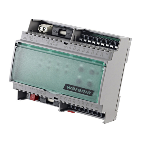
Fig. 1 Omnexo switch actuator1M230UP
The Omnexoswitch actuator1M230UP is a device for the
central operation of a sun shading drive.
Its compact design enables flush mounting in junction
boxes.
It is operated via the Omnexo
control system. The drives and switch actuator are supplied
with 230 V AC and those of the switch actuator with 24 V
DC.
The Omnexoswitch actuator1M230UP functionality
can be set. The control behaviour can be adjusted to the
different requirements of the various products.
Controlling the light and load is not permitted and
will result in a device fault.
Intended use
The Omnexoswitch actuator1M230UP is an electronic
device for controlling sun shading devices. The approval
of the manufacturer must be obtained for any use of the
device other than its intended purpose specified in these
instructions.
The sun shading actuator is intended for installation in
enclosed electrical operating facilities.
Safety instructions
ARNINGW
The electrical installation (assembly)/
dismantling must be performed by a
certified electrician in accordance with
VDE0100 and/or with the standards
and legal requirements pertaining to
the respective country. The electrician
must observe the installation notes and
instructions included with the electrical
devices supplied.
Installation instructions
Omnexo switch actuator
1M230 UP
Valid from
1 April 2023
Keep for future use.
warema_2052437_alhb_en_v2•2023-04-01We reserve the right to make technical modifications
2
Function of the sun shading actuator
You will find a detailed description of the functions for
Omnexo sun shading actuators in the Omnexo software.
The software is available to download at
www.warema.com/en/omnexo/.
Installation
The device is designed for installation in a flush-mounted
junction box 80 x 80 mm. The space in a 60 mm flush-
mounted switch box is usually not sufficient.
 Only lines that are used for the wiring of the actuator
should be routed into this box.
 Check that the actuator is functioning properly before
the final installation.
Electrical connection
An on-site overload current protection device (fuse) and a
disconnecting and isolating switch to switch off the entire
unit must be provided. When using control lines according
to VDE 0815 or not approved for 230 V AC, e.g. JY(St)Y
leads, the enclosed silicone tubes must be pulled over the
wires of the 24 V-control line and the pushbutton line.
The power supply for the Omnexoswitch
actuator1M230UP is provided by a separate 24 V DC
power supply unit.
The unit is electrically connected according to the wiring
diagram on the other side of the page (Fig. 4).
The bus lines must be provided with 120 Ω termi-
nating resistors at the beginning and end of the
line.
12
Fig. 2 Connecting and disconnecting the line connections
 Stripping the wire
 Press the wire into the terminal until the insulation
on the wire enters the terminal and the conductor is
securely held in the terminal (1).
 Disconnect the line:
press the corresponding unlock button as far as it will
go using a screw driver and then remove the conductor
from the terminal (2).
Commissioning
After the installation has been completed and the supply
voltage is applied, the device needs to be taken into
service using the Omnexo software.
The actuator will only work in dead man's mode until it has
been successfully commissioned.
You will find a detailed description on commissioning in the
Omnexo software under "Help".
Information on commissioning and the
Omnexo app is available at:
www.warema.com/en/omnexo/
Maintenance
There are no parts inside the device that require
maintenance.
Cleaning
Clean the housing with a soft, dry cloth. Do not use
detergents, cleaning agents, solvents, abrasive substances
or steam cleaners!
Liability
Failure to comply with the product information in these
instructions and any use of the device other than its
intended use may result in the manufacturer refusing to
honour warranty claims for product damage. In this case,
liability for secondary harm to persons or damage to
property will also be excluded. Observe the information in
the operating instructions for your sun shading system. The
automatic or manual operation of the sun shading system
while iced over and the use of the sun shading system
during severe weather may cause damage and must be
prevented by the operator through suitable precautions.
Obligations for the disposal of electrical
devices
A marking with this symbol indicates the following
obligations under the scope of legal regulations:
 The owner of this electrical device must dispose of it
separately from unsorted municipal waste for further
recycling.
 Used batteries and accumulators that are not enclosed
in the old device, as well as lamps/bulbs that can be
removed from the old device without breaking, must be
disposed of separately.
 Distributors of electrical devices and disposal
companies are obliged to take back the equipment free
of charge.
 The owner must take it upon themselves to delete any
personal data contained in the electrical device prior to
disposal.
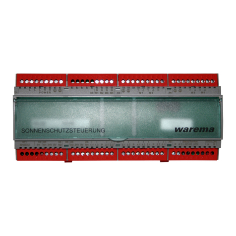
3
warema_2052437_alhb_en_v2•2023-04-01 We reserve the right to make technical modifications
Technical data
Omnexo switch
actuator1M230UP
min. type max. Unit
Supply
Operating voltage (SELV) 15 24 26.4 VDC
Current consumption 10 57 mA
Outputs
Switching capacity 230VAC/
cosφ = 0.6 700 VA
Inputs
Local operator inputs "Input
active"
824 36 VDC
Omnexo interface
Bus interface RS485 (two-wire bus)
Housing
Dimensions 45 x 46 x 21 mm (WxHxD)
Housing type flush-mounted housing
Degree of protection IP20
Safety class II
Installation
Flush-mounted box (depth >
65mm)
Miscellaneous
Software class A
Conformity
Available at www.warema.de/ce
This device complies with the EMC directives for use in
residential and commercial areas.
Ambient conditions
Operating temperature 0 50 °C
Storage temperature 0 70 °C
Humidity
(not condensing) 10 85 %RH
Degree of soiling 2
Connection
Connecting line (24 V DC) Spring terminal
Permissible conductor diameter 0.6 - 0.8mmx
Stripping length 6.5mm
Motor outputs Screw terminal
Permissible line cross-section 0.5 - 1.5mm²
Stripping length 6.4 mm
Inputs Spring terminal
Permissible conductor
diameter
0.6 - 0.8mmx
Stripping length 6.5mm
Omnexo interface Spring terminal
Permissible conductor diameter 0.6 - 0.8mmx
Stripping length 6.5mm
Article numbers
Omnexo switch
actuator1M230UP
2047077
WAREMA Renkhoff SE
Hans-Wilhelm-Renkhoff-Str. 2
D-97828 Marktheidenfeld
Germany
Dimensions
21 mm 46 mm
45 mm
Fig. 3 Housing dimensions for installation in a
flush-mounted box
Inscription on the actuator (see Fig. 4 on page 4):
L button Button to transmit the serial number to the central
control unit
LED status
with two
functions:
LED lights up:
voltage is applied
LED flashes:
bus communication
is taking place
warema_2052437_alhb_en_v2•2023-04-01We reserve the right to make technical modifications
4
local button
LED Status +24V0VIn+BA
RS485
C
C
output
Omnexo Schaltaktor
1M230 UP
+
2 x 2 x 0,8 mm ∅
push button push button
To operate several Omnexo
switch actuators with the
same push button, the push
button line must be
connected to all actuators.
Attention!
Voltage 24 V DC must be
SELV in accordance with
VDE0700-1 and EN
60335-1.
to other
switch actuators
0 V
24 V
Bus A
Bus B
L:
Button to transmit the
serial number to the
central control unit
M∼
Motor
sun shading system
1 32
BU BK BN GNYE
NPE
All motor lines
H05-RR-F 4 G 0.75 BK,
type WAREMA
L
N
PE
connecting line
230 V AC,
50/60 Hz, 16 A,
3 x 1.5 mm2
from previous
bus device
to other
switch actuators
All push button lines
JY(St)Y 2×2×0.8 mm
Max. line length 200m
for interference-proof routing,
use a twisted paired line.
All bus lines
JY(St)Y 4×2×0.8 mm
Attention!
Only one drive can be
connected per
Omnexo switch actuator 1M230 UP !
Fig. 4 Connection example push button and motor
KEEP IN A SAFE PLACE FOR COMMISSIONING!
Affix the switch actuator ID label here
00001357 Aktor
Note down installation location here
Allocation:
Output Product/sun shading system Designation/room Facade Formation of groups
M 1
Example External venetian blind ➊ Ground floor office on the left ➋ East ➌ Ground floor office ➍
➊ Product/sun shading system: information on the type of
sun shading product
➌ Facade: information on the orientation of the facade for the
corresponding
sun shading product
➋ Designation/room: information on the installation location for
the corresponding
sun shading product
➍ Formation of groups: information on the formation of operating
groups
in the Omnexo system

Other WAREMA Controllers manuals

WAREMA Omnexo 2M230 REG User manual

WAREMA

WAREMA Omnexo 2M230 REG User manual

WAREMA KNX SA Series User manual

WAREMA

WAREMA KNX SA Series User manual

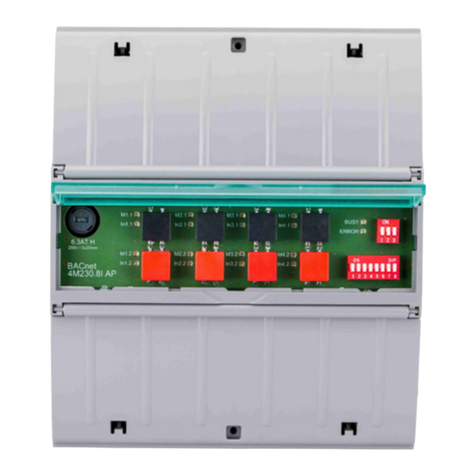
WAREMA BACnet 4M230.8I AP User manual

WAREMA

WAREMA BACnet 4M230.8I AP User manual

WAREMA 1MPF.4 UP User manual

WAREMA

WAREMA 1MPF.4 UP User manual

WAREMA KNX SA 16M230 SMI REG User manual

WAREMA

WAREMA KNX SA 16M230 SMI REG User manual

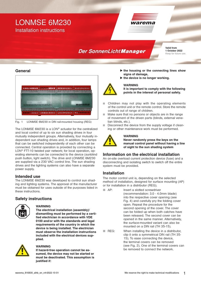
WAREMA LONMSE 2M230I Manual

WAREMA

WAREMA LONMSE 2M230I Manual

WAREMA KNX SA 2M230 AP Series User manual

WAREMA

WAREMA KNX SA 2M230 AP Series User manual

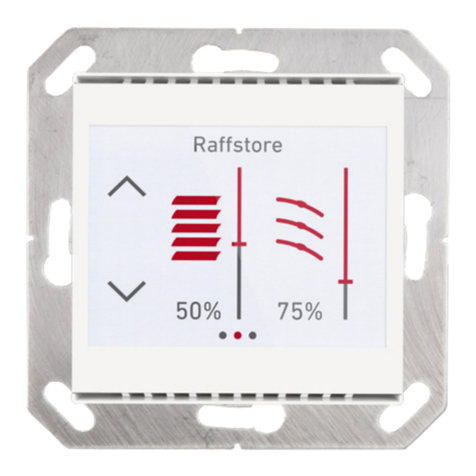
WAREMA Omnexo 2M230 AP User manual

WAREMA

WAREMA Omnexo 2M230 AP User manual

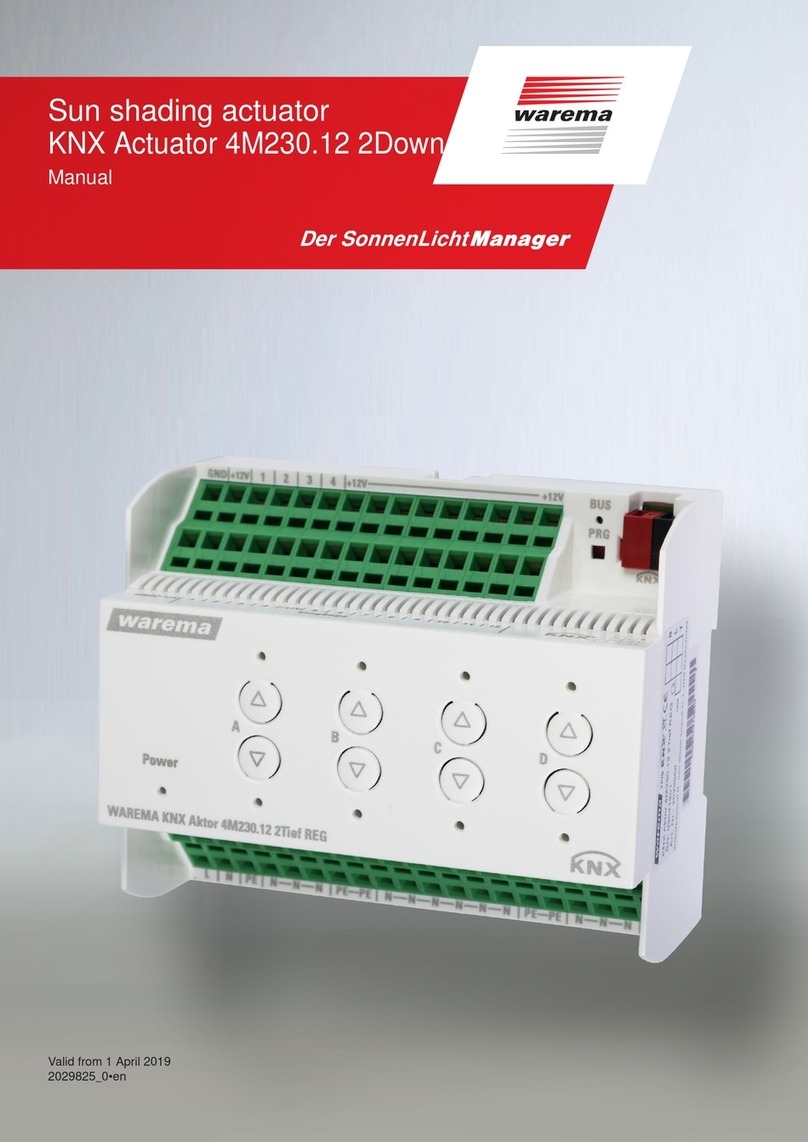
WAREMA 4M230.12 2Down REG User manual

WAREMA

WAREMA 4M230.12 2Down REG User manual

WAREMA LONMPM 8DI User manual

WAREMA

WAREMA LONMPM 8DI User manual

WAREMA KNX SA 4MDC.8 AP User manual

WAREMA

WAREMA KNX SA 4MDC.8 AP User manual

WAREMA KNX SA 2M230 REG User manual

WAREMA

WAREMA KNX SA 2M230 REG User manual

WAREMA KNX SA 4MDC REG User manual

WAREMA

WAREMA KNX SA 4MDC REG User manual

WAREMA KNX secure Series User manual

WAREMA

WAREMA KNX secure Series User manual

WAREMA KNX SA 2M230 REG User manual

WAREMA

WAREMA KNX SA 2M230 REG User manual

WAREMA LONMSE 6M230 User manual

WAREMA

WAREMA LONMSE 6M230 User manual

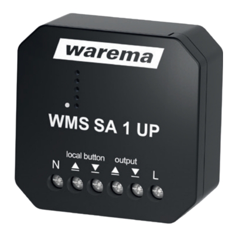
WAREMA WMS SA 1 UP User manual

WAREMA

WAREMA WMS SA 1 UP User manual

WAREMA KNX SA 4MDC.8 AP User manual

WAREMA

WAREMA KNX SA 4MDC.8 AP User manual

WAREMA KNX MSE 6M230 Series User manual

WAREMA

WAREMA KNX MSE 6M230 Series User manual

WAREMA KNX secure Series User manual

WAREMA

WAREMA KNX secure Series User manual

WAREMA KNX SA 16M230.32 SMI AP User manual

WAREMA

WAREMA KNX SA 16M230.32 SMI AP User manual

WAREMA KNX 2024236 User manual

WAREMA

WAREMA KNX 2024236 User manual

WAREMA KNX SA 16M230.32 SMI AP User manual

WAREMA

WAREMA KNX SA 16M230.32 SMI AP User manual

WAREMA LONMSE 2M230 Manual

WAREMA

WAREMA LONMSE 2M230 Manual

Popular Controllers manuals by other brands

NI MXI-Express Gen II x8 Series user manual

NI

NI MXI-Express Gen II x8 Series user manual

alre KTRTB-251.108 manual

alre

alre KTRTB-251.108 manual

Autonics TZN Series manual

Autonics

Autonics TZN Series manual

Datakom DK-40 user manual

Datakom

Datakom DK-40 user manual

FUTABA MCP-2 instruction manual

FUTABA

FUTABA MCP-2 instruction manual

Cooper Power Systems VR-32 quick start guide

Cooper Power Systems

Cooper Power Systems VR-32 quick start guide

Curtis MultiMode 1207B manual

Curtis

Curtis MultiMode 1207B manual

Bosch Plena LBB1990/00 Use manual

Bosch

Bosch Plena LBB1990/00 Use manual

Denon MC2000 Quick setup guide

Denon

Denon MC2000 Quick setup guide

Signature Share 8340 quick start guide

Signature

Signature Share 8340 quick start guide

SmartLine SL800 installation instructions

SmartLine

SmartLine SL800 installation instructions

SMSC USB2250 datasheet

SMSC

SMSC USB2250 datasheet

Fisher 912 Series instruction manual

Fisher

Fisher 912 Series instruction manual

Honeywell SUPER TRADELINE S8610U installation instructions

Honeywell

Honeywell SUPER TRADELINE S8610U installation instructions

VECTOR CONTROLS T-EF Series quick start guide

VECTOR CONTROLS

VECTOR CONTROLS T-EF Series quick start guide

STW TC1 user manual

STW

STW TC1 user manual

Cypress CapSense CY8CMBR2044 Design guide

Cypress

Cypress CapSense CY8CMBR2044 Design guide

Electronic Research Group EC130 Technical manual

Electronic Research Group

Electronic Research Group EC130 Technical manual

manuals.online logo
manuals.online logoBrands
  • About & Mission
  • Contact us
  • Privacy Policy
  • Terms and Conditions

Copyright 2025 Manuals.Online. All Rights Reserved.