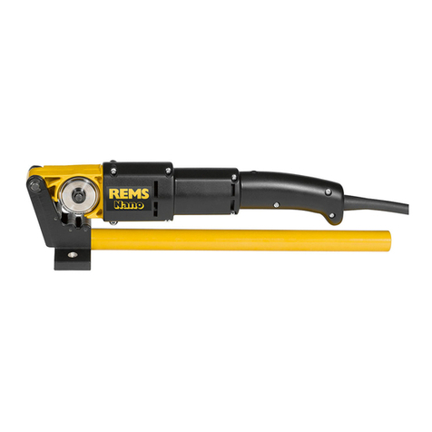
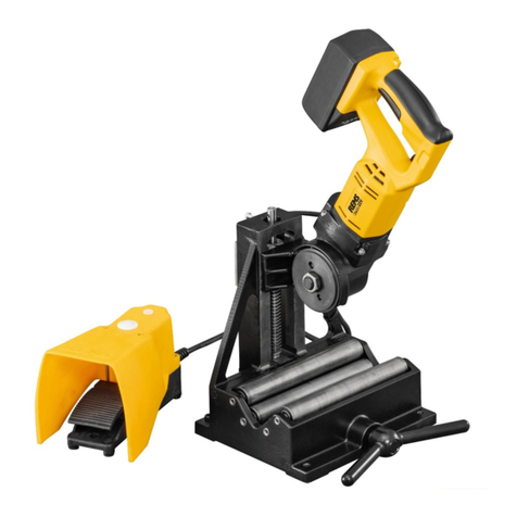
REMS Python User manual

BENDING
INSTRUCTION MANUAL
PART 1:
REMS Python
REMS Swing
REMS Hydro Swing 22V
PART 2:
REMS Curvo
REMS Curvo 50
REMS Akku Curvo
REMS Sinus

2
PART 1
REMS Python
REMS Swing
REMS Hydro Swing 22V

3
Fig. 2
12
12
8 mm
8 mm
Fig. 1
16
15
6
14
12
11
4
5
5
1
2
7
10
17
17
13
Fig. 3
21
22
Biege-
segment
für Rohre
Ø Zoll/mm
Biege-
radius
1)
mm
Biege-
radius
2)
mm
Geeignet für
St 10255
V
St ⅜"
50
590051
R
St ½"
65
590052
R
St ¾"
85
590053
R
St 1"
100
590054
R
St 1¼"
150
590055
R
St 1½"
170
590056
R
St 2"
220
590057
R
V 32 mm
112
128
590061
R
V 40 mm
140
160
590058
R
V 50 mm
175
200
590059
R
V 63 mm
220
252
590060
R
V 75 mm
260
298
590062
R
St 10255: Stahlrohre (Gewinderohre) EN 10255
V: Verbundrohre der Pressfi tting-Systeme
Gleitstück Ø 75 mm, 2er-Pack (Art.-Nr. 590111), erforderlich
1)
Biegeradius mm der Innenseite des Bogens (EN 10255)
2)
Biegeradius mm der neutralen Achse des Bogens (DVGW VP 632)
2
Bending
Segment for
Tubes
ø inch/mm
Bending
Steel Pipes (threaded pipes) EN 10255
Compositepipesofthepressttingsystem
SlidingPieceø75mm,2-pack(ArtNo:590111),necessary
Bendingradiusmmoftheinsideofthebend(EN10255)
Bendradiusmmoftheneutralaxisofthebend(DVGWVP632)
Bending
Suitable for

4
7
9
7
7
3
11
18
10
8
4
Fig. 4
15
Fig. 6
Fig. 5
19
20
1)
Biegeradius mm der neutralen Achse des Bogens (DVGW GW 392)
Cu: weiche Kupferrohre, auch dünnwandig
St 10305-U: weiche ummantelte C-Stahlrohre der Pressfi tting-Systeme
EN 10305-3
St 10305: weiche Präzisionsstahlrohre EN 10305-1, EN 10305-2,
EN 10305-3
U: ummantelt
V: Verbundrohre der Pressfi tting-Systeme
Biegesegment
für Rohre
Ø mm/Zoll
Biege-
radius
1)
mm
Geeignet für
Cu
Cu-U
St 10305-U
St 10305
V
10, ⅜
30
●
●
153155
R
12, 10 U, ½
36
●
●
●
153160
R
14, 12 U
50
●
●
●
●
153170
R
15, 12 U, ⅝
55
●
●
●
153175
R
16, 14 U
55
●
●
●
●
153180
R
17, 15 U
60
●
●
153185
R
18, 14 U, 15 U, 16 U, ¾
72
●
●
●
●
153190
R
20, 18 U
79
●
●
●
●
153195
R
22, 18 U, ⅞
86
●
●
153200
R
25, 26
88
●
153205
R
32
128
●
153210
R
3
Bending Segment
for Pipes
ø inch/mm
Suitable for:
Bending
Radius
1)
Bendradiusmmoftheneutralaxisofthebend(DVGWGW392)
Cu: softcoppertubes,alsothin-walled
St10305-U: softcoatedcarbonsteelpipesofthepressttingsystem
EN10305-3
St10305: softprecisionsteeltubesEN10305-1,EN10305-2,
EN10305-3
U: encased
V: compositepipesofthepressttingsystems

5
Fig. 7
3
7
15
10
8
4
1
1
9
13
15
Biegesegment
für Rohre
Ø mm/Zoll
Biege-
radius
1)
mm
Geeignet für
Cu
Cu-U
Hydro-Swing INOX
St 10217
St 10305
St 10305-U
V
10, ⅜
30
153155
12, 10 U, ½
36
153160
14, 12 U
50
153170
15
2)
55
153531
15, 12 U, ⅝
55
153175
16, 14 U
55
153180
17, 15 U
60
153185
18
2)
72
153532
18, 14 U, 15 U, 16 U, ¾
72
153190
20, 18 U
79
153195
22, 18 U, ⅞
2)
86
153540
25, 26
88
153205
32
128
153210
1)
Biegeradius mm der neutralen Achse des Bogens (DVGW GW 392)
2)
Biegesegmente aus Aluminium
Cu: weiche Kupferrohre, auch dünnwandig, EN 1057
St 10217: nichtrostende, nickelhaltige Stahlrohre der Pressfi tting-Systeme
EN 10217-7, EN 10312, Reihe 2, Werkstoff 1.4401
St 10305:
weiche Präzisionsstahlrohre EN 10305-1, EN 10305-2, EN 10305-3
St 10305-U: weiche ummantelte C-Stahlrohre der Pressfi tting-Systeme
EN 10305-3
U: ummantelt
V: Verbundrohre der Pressfi tting-Systeme
REMS Hydro-Swing INOX Set.
REMS Hydro-Swing
mit Biegesegmenten aus Aluminium, insbesondere auch für
Geberit Mapress Edelstahl (EN 10088, 1.4401),
Geberit Mapress Edelstahl (EN 10088, 1.4521, nickelfrei),
Geberit Mapress C-Stahl (EN 10305-3, 1.0034 (E195)),
Viega Sanpress (EN 10088, 1.4401),
Viega Prestabo (EN 10305-3, 1.0308 (E235)).
4
Fig. 8
Fig. 9
Bending Segment
for Tube
ø inch/mm
Suitable for:
Bending
Radius
1)Bendingradiusmmoftheneutralaxisofthearc(DVGWGW392)
2)Aluminumbendingsegments
Cu: softcoppertubes,alsothin-walled,EN1057
St10217: softcoatedcarbonsteelpipesofthepressttingsystem
EN10305-3
St10305: softprecisionsteeltubesEN10305-1,EN10305-2,
EN10305-3
St10305-U:
softcoatedcarbonsteelpipesofthepressttingsystem
EN10305-3
U: encased
V: compositepipesofthepressttingsystems

6
eng eng
Translation of the Original Instruction Manual
General Safety Instructions
CAUTION
CAUTION
Re
ad all the safety notes, instructions, illustrations and technical data which
come with this tool.
Failure to heed the safety notes and instructions can lead to
severe injuries.
Keep all safety notes and instructions for the future.
Only use the tool for the intended purpose and under observance of the general
safety and accident prevention rules.
a) Ke
ep your workplace tidy.
Untidiness in the work area can cause accidents.
b) Use the right tool.
Do not use weak machines for heavy work. Do not use the
tool for a purpose for which it is not intended.
c) Check the tool for damage.
Slightly damaged parts must be checked carefully
for perfect and proper functioning before using the tool. Check whether the moving
parts work perfectly and do not jam or are damaged. All parts must be mounted
correctly and meet all conditions to ensure perfect operation of the tool. Damaged
parts must be properly repaired or changed by a recognised specialist unless
specifi ed otherwise in the operating manual.
d) Be careful.
Pay attention to what you are doing. Work sensibly.
e) Do not overload your tool.
You can work better and safer in the specifi ed work
range. Renew worn tools in time.
f) Wear suitable work clothing.
Do not wear loose clothing or jewellery as these
can get caught in moving parts. Rubber gloves and non-slip shoes are recom-
mended for working outdoors. Wear a hair net over long hair.
g) Use safety equipment.
Wear safety glasses. Wear protective gloves.
h) Avoid abnormal body posture.
Make sure that you have a fi rm footing and
keep your balance at all times.
i) Take good care of your tools.
Keep the tools clean to work better and safer.
Follow the maintenance regulations and instructions. Keep handles dry and free
from grease and oil.
j) Take ambient infl uences into account.
Do not expose your tools to rain. Provide
good lighting.
k) Keep other persons away.
Do not let other persons touch your tools. Keep other
persons and especially children away from your work area.
l) Only use genuine accessories and genuine spare parts for your own safety
for the intended function of the tool.
The use of other insertion tools and
accessories can cause you injury.
m) Have your tool repaired by a qualifi ed specialist.
This tool satisfi es the perti-
nent safety regulations. Repairs may only be done by a recognised specialist or
instructed person with the use of genuine spare parts, otherwise the user could
have an accident. All unauthorised modifi cations to the tool are prohibited for
safety re
asons.
Safety instructions for oil-hydraulic pipe benders, one-
hand pipe benders, oil-hydraulic hand pipe benders
CAUTION
CAUTION
Read all t
he safety notes, instructions, illustrations and technical data which
come with this tool.
Failure to heed the safety notes and instructions can lead to
severe injuries.
Keep all safety notes and instructions for the future.
●
Do not use the tool if it is damaged.
There is a danger of accident.
●
Do not reach between the pipe, rollers/back formers (7) and the bending
former (10) during bending.
There is a risk of injury.
●
Protect persons accompanying the work against the moving pipe during
bending.
There is a risk of injury.
●
Be careful when bending with REMS Python and REMS Hydro-Swing. These
develop a high bending force.
There is a danger of injury in case of improper
use.
●
Do not lift or carry the REMS Python by the attached advance lever (11).
The advance lever is only inserted but not secured. The bender drive (4) can
come loose from the advance lever (11) and fall off.
There is a risk of injury.
●
Children and persons who, due to their physical, sensory or mental abilities
or lack of experience and knowledge are unable to operate the tool safely
may not use this tool without supervision or instruction by a responsible
person. Otherwise there is a risk of operating errors and injuries.
●
Only allow trained persons to use the tool. Apprentices may only use the
tool when they are over 16, when this is necessary for their training and
when they are supervise
d by a trained operative.
Explanation of symbols
CAUTION
CAUTION
Danger with a low degree of risk which could result in minor
injury (reversible) if not heeded.
NOTICE
NOTICE
Material damage, no safety note! No danger of injury.
Read the operating manual before starting
CE conformity ma
rk
Fig. 1 – 3
1 Lower roller holder
2 Upper roller holder, with laterally
adjustable roller bearing plate
3 Back former support
4 Bending drive
5 Bolt
6 Spring loaded pin
7 Rollers / Back formers
8 Rack/advance plunger
9 Wing nut
10 Bending former
11 Advance lever
12 Locking screw
13 Return valve
14 Angle marking
15 Marking for precise bending
16 Foot
17 Scale
18 Arrow direction
19 Bending former holder
20 Back former support holder
21 Bridge
22 Doglegs on several levels
1. Technical Data
Use for the intended purpose
CAUTION
CAUTION
REMS Python, REMS Swing, REMS Hydro-Swing are intended for the purpose of cold pressure bending of pipes up to 90°.
All other uses are not for the intended purpose and are therefore prohibited.
1.1. Scope of Supply
REMS Python: Oil-hydraulic pipe bender, 2 roller holders, 2 rollers, bending formers according to ordered set, operating instructions,
transport box.
REMS Swing up to Ø 26 mm: One-hand pipe bender, bending formers according to ordered set, back former supports S Ø 10 – 26 mm, steel case,
operating instructions.
REMS Swing up to Ø 32 mm: One-hand pipe bender, bending formers according to ordered set, back former supports S Ø 10 – 26 mm, back former
supports Ø 32 mm, case, operating instructions.
REMS Hydro-Swing up to Ø 26 mm: Oil-hydraulic hand pipe bender, bending formers according to ordered set, back former supports H-S Ø 10 – 26 mm,
case, operating instructions,
REMS Hydro-Swing Ø 32 mm: Oil-hydraulic hand pipe bender, bending formers according to ordered set, back former supports H-S Ø 10 – 26 mm,
back former supports Ø 32 mm, case, operating instructions.
REMS Hydro-Swing INOX Set: Oil-hydraulic hand pipe bender, aluminium bending formers Ø 15, 18, 22 mm, back former support H-S Ø 10 – 26 mm, case,
operating instructions.
1.2. Article numbers REMS Python REMS Swing REMS Hydro-Swing REMS Hydro-Swing INOX
Drive unit 590000 153100 153500 153510
Bending formers see Fig. 3 see Fig. 6 see Fig. 8 see Fig. 8
Roller (pack of 2) 590110
Back former Ø 75 mm (pack of 2) 590111
Back former support S Ø 10–26 mm 153125
Back former support H-S Ø 10–26 mm 153501 153501
Back former support Ø 32 mm 153115 153115 153115
Tripod stand 590150
Device for reverse bend 153140

Transport box 590160
9

7
eng eng
2. Start-up
CAUTION
CAUTION
Observe and follow the national rules and regulations for manual handling of
load weights.
2.1. REMS Python Fig. 1 – 3
Place the bender drive (4) on a fi rm, level base. Make sure that there is enough
room for the fully assembled pipe bender and the pipe to be bent. Insert the
lower roller holder (1) into the lower groove of the bender drive (4) so that the
feet (16) are facing down and the bolt (5) can be inserted. Secure the bolt (5)
with the spring loaded pin (6). Insert the upper roller holder (2) into the upper
groove of the bender drive (4) so that the angle marking (14) is legible, fi x with
the bolt (5), secure the bolt with the spring-loaded pin (6). Insert the rollers (7)
according to the pipe size, see scale (17), into the holes between the roller
holders (1 and 2). To bend composite pipes with a diameter of 75 mm, insert
the 75 mm diameter back formers (accessory) between the roller holders (1
and 2) in place of the rollers (7). The roller bearing plate of the upper roller
holder (2) can be moved to the side if necessary, e.g. to form a dogleg (22).
The rollers must always be inserted into the holes of the upper and lower roller
holder (1 and 2) for bending. Select the suitable bending former for the pipe
size (10) and fi t it on the bender drive (4). Push the advance lever (11) onto
the bender drive (4). Open the locking screw (12) about 1 turn. Close the return
valve (13) by turning in and screw hand tight.
2.2. REMS Swing Fig. 4 – 6
Place the back former support (3) on the bender drive (4) so that the back formers
(7) for the desired pipe size are facing towards the rack (8). The back formers
are marked with the pipe size. Fix the back formers (3) with the wing nut (9).
Select the suitable bending former (10) for the pipe size and fi t it on the rack
(8). Press down the advance lever (11) in the direction of the arrow (18) and
push back the bending former (rack) to the rear stop. Release the advance lever.
Device for reverse bend Fig. 5 (accessory)
Place the bending former holder (19) on the bender drive (4) so that the holder
for the bending former is facing towards the rack (8). Fix the bending former
holder (19) with the wing nut (9). Fit the back former support holder (20) to the
rack (8). Fix the back former support holder (20) with the wing nut. Place the
back former support (3) in the back former support holder (20) so that the back
formers (3) for the desired pipe size are facing towards the bending former
holder (19). The back
formers (7) are marked with the pipe size. Fix the back
former support (3) with the wing nut. Select the suitable bending former (10)
for the pipe size and fi t it on the bending former holder (19). Press down the
advance lever (11) in the direction of the arrow (18) and push back the back
former support (rack) to the rear stop. Release the advance lever.
2.3. R
EMS Hydro-Swing Fig. 7 – 8
Place the back former support (3) on the bender drive (4) so that the back
formers (7) for the desired pipe size are facing towards the advance lever (8).
The back formers are marked with the pipe size. Fix the back former support
(3) with the wing nut (9). Select the bending former (10) suitable for the pipe
size, align the square pin of the advance plunger (8) to the square pin of the
bending former (10) by swivelling the advance lever and fi t the bending former
onto the advance plunger (8). Close the return valve (13) by turning in and
screw hand tight. The bender drive (4) can be turned approx. 360°. Then the
advance lever (11) can be positioned to the bending former (10) and back
former support (3) as required.
3. Operation
3.1. REMS Python Fig.
1 – 3
Lift up the upper roller support (2). Insert the pipe between the rollers (7) and
the bending former (10). Close the upper roller support (2). Move the advance
lever (11) up and down several times until the pipe has reached the desired
bending angle. Open the return valve (13) by about 1 turn, the bending former
(10) returns to the starting position with the pipe bend. Lift up the upper roller
holder (2) and remove the bent pipe. The bending formers St 1" to St 2" have
a hexagon head screw. This can be used to press out a pipe jammed in the
bending former.
There is an angle marking (14) on the upper roller holder (2) for orientation for
the bending angle.
NOTICE
NOTICE
To ensure functional reliability and to prevent hydraulic oil leakage, the locking
screw (12) must be closed after bending has been completed and for transport
of the bender drive.
3.2. REMS S
wing Fig. 4 – 6
Turn the back formers (7) so that radius on the back former corresponding to
the pipe size is on the side facing the bending former (10). Insert the pipe
between the bending former (10) and the back formers (7). Push the advance
lever (11) several times opposite to the direction of the arrow (18), u
ntil the pipe
has reached the desired bending angle. Push the advance lever (11) in the
direction of the arrow (18) and push back the bending former, if necessary with
the bent pipe. Remove the pipe.
REMS Python REMS Swing REMS Hydro-Swing REMS Hydro-Swing INOX
Steel case with inlay
153265
Case with
inlay
153270 153570 153570
Angle meter 590153 590153 590153 590153
REMS CleanM 140119 140119 140119 140119
1.3. Applications
No cracks or wrinkles shall occur during professional cold bending. Pipe qualities and dimensions which do not guarantee this are not suited to be bent
with REMS Python, REMS Swing and REMS Hydro-Swing.
Steel pipes EN 10255 Ø ⅜ – 2"
Soft copper pipes, also thin-walled Ø 10 – 22 mm, s ≤ 1 mm Ø 10 – 22 mm, s ≤ 1 mm Ø 10 – 22 mm, s ≤ 1 mm
Ø ⅜ – ⅞"
Ø ⅜ – ⅞"
Ø ⅜ – ⅞"
Soft coated copper pipes Ø 10 – 18 mm, s ≤ 1 mm Ø 10 – 18 mm, s ≤ 1 mm Ø 10 – 18 mm, s ≤ 1 mm
Ø ⅜ – ⅝"
Ø ⅜ – ⅝"
Ø ⅜ – ⅝"
Stainless, nickel steel pipes of the press fi tting
systems EN 10217-7, EN 10312 series 2,
material 1.4401 Ø 12 – 22 mm, s ≤ 1.2 mm Ø 12 – 22 mm, s ≤ 1.2 mm
Stainless steel pipes of the press fi tting systems
with aluminium bending formers, see fi g. 8 Ø 15 – 22 mm, s ≤ 1.2 mm
Steel pipes of the press fi tting systems
with aluminium bending formers, see fi g. 8 Ø 15 – 22 mm, s ≤ 1.5 mm
Soft coated carbon steel pipes
of the pressfi tting systems Ø 12 – 18 mm, s ≤ 1,2 mm Ø 12 – 18 mm, s ≤ 1.2 mm
Soft precision steel pipes Ø 10 – 18 mm, s ≤ 1 mm Ø 10 – 22 mm, s ≤ 1.5 mm
Composite tubes Ø 32 – 75 mm Ø 14 – 32 mm Ø 14 – 32 mm Ø 14 – 32 mm
Largest bending angle 90° 90° 90° 90°
Hard copper pipes must be softened by annealing!
1.4. Dimensions L × W × H
Bender drive with
Roller holder/back former support 670 × 680 × 620 mm 318 × 252 × 140 mm 428 × 252 × 170 mm 428 × 252 × 170 mm
(26.4" × 26.8" × 24.4") (12.5" × 9.9" × 5.5") (16.9" × 9.9" × 6.7") (16.9" × 9.9" × 6.7")
Tripod stand 650 × 630 × 525 mm
(25.6" × 24.8" × 20.7")
1.5. Weights
Bender drive with
Roller holder/back former support 35.0 kg (77.2 lb) 1.4 kg (3.1 lb) 3.1 kg (6.8 lb) 3.1 kg (6.8 lb)
Tripod stand 4.6 kg (10.1 lb)
Bending formers from – to 0.4 – 4.9 kg 0.06 – 0.3 kg 0.06 – 0.3 kg 0.06 – 0.3 kg
(0.9 – 10.8 lb) (0.13 – 0.7 lb) (0.13 – 0.7 lb) (0.13 – 0.7 lb)
10

8
eng eng
NOTICE
NOTICE
The bending formers (10) and the back formers (7) of REMS Swing are made
of glass-fi bre-reinforced polyamide. This plastic have very good slide properties,
is very strong and heat resistant up to approx. 150 °C. Annealed copper pipes
must be cooled down below this temperature.
3.3. REMS Hydro-Swing Fig. 7 – 8
Turn the back formers (7) so that radius on the back former corresponding to
the pipe size is on the side facing the bending former (10). Insert the pipe
between the bending former (10) and the back former (7). Move the advance
lever (11) up and down several times until the pipe has reached the desired
bending angle. Open the return valve (13) by about 1 turn and the bending
former (10) returns to the starting position with the pipe bend. Remove the pipe.
NOTICE
NOTICE
The bending formers (10) and the back formers (7) of REMS Hydro-Swing are
made of glass-fi bre-reinforced polyamide. This plastic have very good slide
properties, is very strong and heat resistant up to approx. 150°C. Annealed
copper pipes must be cooled down below this temperature.
The aluminium bending formers Ø 15, 18, 22 mm must be used for bending
stainless steel pipes and carbon steel pipes, see fi g. 8.
3.4. Bending to size Fig. 9
There are 2 markings (15) on the outside of the bending formers (10) which
allow exact bending to size. To do this, the dimension mark at which the 90°
bend is to end must be placed against the marking (15) over the centre.
4. Maintenance
4.1. Maintenance
In the REMS Python, check the advance lever (11) regularly for damage,
change damaged advance lever. REMS Swing and REMS Hydro-Swing are
maintenance-free.
Clean the pipe bender regularly especially when it has not been in use for a
long time. Keep the bending contours of bending former (10) and rollers/back
formers (7) clean. Use REMS CleanM (Art.-No. 140119) or mild soap and a
damp cloth for cleaning. Do not use household cleaners. These often contain
chemicals which can damage the plastic parts. Never use petrol, turpentine,
thinner or similar products for cleaning. Never immerse the pipe bender in liquid.
4.2. Inspection/Repair
CAUTION
CAUTION
This work may only be performed by qualifi ed personnel.
In REMS Python, check hydraulic oil (Fig. 2), refi ll hydraulic oil (Art. No. 091027)
if necessary. Do not overfi ll, otherwise hydraulic oil will leak during work.
5. Behaviour in the event of faults
5.1.
Fault:
Bending former (10) does not advance despite moving the advance lever (11) up and down several times.
Cause:
Remedy:
●
Return valve (13) not closed (REMS Python, REMS Hydro-Swing).
●
Close the return valve (13) by turning in and screw hand tight.
●
Not enough hydraulic oil in the system.
●
Refi ll hydraulic oil (in REMS Python (Fig. 2 and 4.2. Inspection/repair). Have
the REMS Hydro-Swing checked/repaired by an authorised REMS customer
service workshop.
●
Air in the system (REMS Python).
●
Open return valve (13) by about 1 turn and move the advance lever (11) up
and down several times until the air has escaped.
●
Advance lever (11) not pushed properly (REMS Swing).
●
Push the advance lever (11) several times, as far as possible, in the opposite
direction to the arrow (18).
●
Overpressure valve responds (REMS Python, REMS Hydro-Swing).
●
Pipe is unsuitable for bending. Only use approved pipes.
●
Pipe bender defective.
●
Have the pipe bender checked/repaired by an authorised REMS customer
service workshop.
5.2.
Fault:
90° bend cannot be fully made.
Cause:
Remedy:
●
Not enough hydraulic oil in the system.
●
Refi ll hydraulic oil (in REMS Python (Fig. 2 and 4.2. Inspection/repair). Have
the REMS Hydro-Swing checked/repaired
by an authorised REMS customer service workshop.
●
Rollers (7) in wrong position between roller holders (1 and 2)
(REMS Python).
●
Insert the rollers (7) according to the pipe size, see scale (17), into the holes
between the roller holders (1 and 2).
●
Back former support (3) fi tted incorrectly (REMS Swing,
REMS Hydro-Swing).
●
Fit back former support as described in 2.2. or 2.3.
●
The strength of the pipe to be bent is too high.
●
Only use approved pipes.
●
Pipe bender defective.
●
Have the pipe bender checked/repaired by an authorised REMS customer
service workshop.
5.3.
Fault:
No useful bend.
Cause:
Remedy:
●
Pipe size does not correspond to the bending former (10) and/or the rollers/
back formers (7).
●
Use bending formers and/or rollers/back formers according to the pipe size.
●
Rollers (7) in wrong position between roller holders (1 and 2)
(REMS Python).
●
Insert rollers according to the pipe size, see scale (17), into the holes
between the roller holders (1 and 2).
●
Back former support (3) fi tted incorrectly (REMS Swing,
REMS Hydro-Swing).
●
Fit back former support as described in 2.2. or 2.3.
●
Pipe is unsuitable for bending.
●
Only use approved pipes.
5.4.
Fault:
Advance lever (11) cannot be pushed or only with diffi culty (REMS Swing).
Cause:
Remedy:
●
Pipe is unsuitable for bending.
●
Only use approved pipes.
●
One-hand pipe bender defective.
●
Have the one-hand pipe bender checked/repaired by an authorised REMS
customer service workshop.
11

9
eng eng
6. Disposal
REMS Python, REMS Swing, REMS Hydro-Swing may not be thrown in the
domestic waste when no longer used. They must be disposed of properly by
law.
7. Manufacturer’s Warranty
The warranty period shall be 12 months from delivery of the new product to the
fi rst user. The date of delivery shall be documented by the submission of the
original purchase documents, which must include the date of purchase and the
designation of the product. All functional defects occurring within the warranty
period, which are clearly the consequence of defects in production or materials,
will be remedied free of charge. The remedy of defects shall not extend or
renew the warranty period for the product. Damage attributable to natural wear
and tear, incorrect treatment or misuse, failure to observe the operational
instructions, unsuitable operating materials, excessive demand, use for unau-
thorized purposes, interventions by the customer or a third party or other
reasons, for which REMS is not responsible, shall be excluded from the warranty.
Services under the warranty may only be provided by customer service stations
authorized for this purpose by REMS. Complaints will only be accepted if the
product is returned to a customer service station authorized by REMS without
prior interference and in a fully assembled condition. Replaced products and
parts shall become the property of REMS.
The user shall be responsible for the cost of shipping and returning the product.
A list of the REMS-authorized customer service stations is available on the
Internet under www.rems.de. For countries which are not listed, the product
must be sent to the SERVICE-CENTER, Neue Rommelshauser Strasse 4,
71332 Waiblingen, Deutschland. The legal rights of the user, in particular the
right to make claims against the seller in case of defects as well as claims due
to wilful violation of obligations and claims under the product liability law are
not restricted by this warranty.
This warranty is subject to German law with the exclusion of the confl ict of laws
rules of German International Private Law as well as with the exclusion of the
United Nations Convention on Contracts for the International Sales of Goods
(CISG). Warrantor of this world-wide valid manufacturer’s warranty is REMS
GmbH & Co KG, Stuttgarter Str. 83, 71332 Waiblingen, Deutschland.
8. Spare parts lists
For spare parts lists, see www.rems.de
→ Downloads → Parts lists.
12

10
PART 2
REMS Curvo
REMS Curvo 50
REMS Akku Curvo
REMS Sinus

11
REMS Curvo / REMS Curvo 50
REMS Curvo 50
1 3 4 7 9
8
10 11
12
5 6
REMS Curvo
1 10
2
3 4 7 9
8
5
6
R88 R114
R140
Fig. 1a
Fig. 1b
R40–R77
R98
R102
13
14
15
16

12
REMS Akku-Curvo
REMS Akku-Curvo
Fig. 1c
1 10
2
3 4 7 8 9 17
5
6
18
R88 R114
R140
R40–R77
R98
R102

13
REMS Curvo / REMS Curvo 50 / REMS Akku-Curvo
Fig. 2 Curvo / Akku-Curvo
Ø mm R mm X mm
10 R 40 45
12 R 45 49
14 R 50 53
15 R 55 56
16 R 60 62
17 R 56 60
18 R 70 75
20 R 75 80
22 R 77 81
22 R 88 91
24 R 75 85
25 R 98 103
26 R 98 108
28 R 102 108
28 R 114 120
30 R 98 105
32 R 98 110
32 R 114 121
35 R 140 150
40 R 140 148
3/8” R 43 48
1/2” R 52 60
5/8” R 63 70
3/4” R 75 82
7/8” R 98 107
1” R 101 112
11/8” R 115 117
11/4” R 133 145
13/8” R 140 150
Curvo 50
35 R 100 105
42 R 140 155
1” R 100 105
11/4” R 140 150

14
eng REMS Curvo / REMS Curvo 50 / REMS Akku-Curvo eng
tool. Power tools are dangerous in the hands of untrained users.
e) Maintain power tools. Check for misalignment or binding of moving parts,
breakage of parts and any other condition that may affect the power tool’s
operation. If damaged, have the power tool repaired before use. Many
accidents are caused by poorly maintained power tools.
f) Keep cutting tools sharp and clean. Properly maintained cutting tools with
sharp cutting edges are less likely to bind and are easier to control.
g) Use the power tool, accessories and tool bits etc. in accordance with these
instructions, taking into account the working conditions and the work to
be performed. Use of the power tool for operations different from those intended
could result in a hazardous situation.
5) Battery tool use and care
a) Recharge only with the charger specied by the manufacturer. A charger
that is suitable for one type of battery pack may create a risk of re when used
with another battery pack.
b) Use power tools only with specically designated battery packs. Use of any
other battery packs may create a risk of injury and re.
c) When battery pack is not in use, keep it away from other metal objects, like
paper clips, coins, keys, nails, screws or other small metal objects, that
can make a connection from one terminal to another. Shorting the battery
terminals together may cause burns or a re.
d) Under abusive conditions, liquid may be ejected from the battery; avoid
contact. If contact accidentally occurs, ush with water. If liquid contacts
eyes, additionally seek medical help. Liquid ejected from the battery may cause
irritation or burns.
6) Service
a) Have your power tool serviced by a qualied repair person using only
identical replacement parts. This will ensure that the safety of the power tool
is maintained.
Safety instructions for electric pipe bending machines
WARNING
Read all safety warnings and all instructions. Failure to follow the warnings and
instructions may result in electric shock, re and/or serious injury.
Save all warnings and instructions for future reference.
●
Use personal safety equipment (protective glasses).
●
Avoid abnormal posture, do not lean too far forward.
●
Do not reach between the pipe and the bending former when bending. Danger
of crushing!!
●
Keep hair and clothing clear of moving parts.
●
Only perform work for which the machine is intended.
●
Keep third persons away from the working area during work.
●
The drive machines develop a very high bending force. So be very careful.
●
The Ni-Cd and Li-Ion batteries cannot be interchanged in the drive unit.
●
If it is necessary to change the plug or the connecting cable, this should only be
done by the manufacturer or his customer service.
Safety instructions for batteries
WARNING
Read all safety warnings and all instructions. Failure to follow the warnings and
instructions may result in electric shock, re and/or serious injury.
Save all warnings and instructions for future reference.
●
Batteries may only be used at battery or ambient temperatures of –10 °C – +60
°C (14 °F – +140 °F).
●
The rapid charger may only be used at rapid charger or ambient temperatures
of 0 °C – +40 °C (32 °F – +104 °F).
●
Observe the safety instructions printed on the battery and the charger.
●
Do not throw defective batteries in the normal household waste. Hand the defec-
tive batteries over to an authorised REMS contract service workshop or a
recognised disposal company.
●
Protect battery from getting wet.
●
Cover the battery contacts when storing outside the tool or rapid charger.
●
Donotopenthebattery.Dangerofexplosionandreduetoshort-circuit.
●
Do not modify the construction of the battery.
●
Only use the battery indoors.
●
Donotusethebatteryinadverseambientconditions,e.g.ammablegases,
solvents, dust, fumes, wet.
●
Do not use the battery if the housing or contacts are damaged.
●
Do not use the battery in areas where there is a danger of explosion.
●
Observe the safety instructions printed on the battery and the charger.
Explanation of symbols
Read the operating instructions before use
Power tool complies with protection class II
Environmentally friendly disposal
CE conformity mark
1. Technical Data
Use for the intended purpose
WARNING
REMS Curvo and REMS Akku-Curvo are intended for the purpose of cold draw
bending of pipes up to 180°.
REMS Curvo 50 is intended for cold draw bending of pipes up to 90°.
All other uses are not for the intended purpose and are prohibited.
1.1. Article numbers
REMS Curvo drive unit 580000
REMS Akku-Curvo drive unit Li-Ion 580002
REMS Curvo 50 drive unit 580100
Square driver 35– 50, support 35–50 582110
Square driver 10– 40, support 10–40 582120
Insert bolt 582036
Rapid charger Li-Ion/Ni-Cd 230 V, 50– 60 Hz, 65 W 571560
REMS battery Li-Ion 18 V, 2.6 Ah 565215
REMS battery Li-Ion 18 V, 3.5 Ah 565217
REMS bending spray, 400 ml 140120
1.2. Capacity
No cracks or wrinkles shall occur during professional cold bending. Pipe quali-
ties and sizes which do not guarantee this are not suited to be bent with REMS
Curvo, REMS Curvo 50 and REMS Akku-Curvo.
Hard copper pipes are cold bendable up to Ø 18 mm according to DIN EN
1057, minimum radii must be complied with. Bending formers and back formers
for larger bending radii can be supplied.
REMS Curvo
●
Hard,half-hard,softcopperpipes,alsothinwalled,Ø10–35mm,⅜–1⅜”.
●
Soft, jacketed copper pipe, also thin walled, Ø 10 –18 mm.
●
StainlesssteelpipesofthepressttingsystemsØ12–28mm.
●
JacketedC-steelpipesofthepressttingsystemsØ12–28mm.
●
SoftprecisionsteelpipesØ10–30mm,wallthickness≤1.5mm.
●
Steel pipes DIN EN 10255 (DIN 2440) ¼” –¾”.
●
Electrical installation pipes DIN EN 50086 Ø 16 –32 mm.
●
Composite pipes Ø 14 –40 mm.
Largest bending angle 180°
REMS Curvo 50
●
Steel pipes as per DIN EN 10255 (DIN 2440) ¼” –1¼”.
●
Hard, half-hard and soft copper tubes Ø 10 –42 mm.
●
Thin walled copper tubes Ø 10 –35 mm.
●
StainlesssteeltubesofpressttingsystemsØ12–42mm.
●
Composite tubes Ø 14 –50 mm.
Largest bending angle 90°
REMS Akku-Curvo
●
Hard,half-hard,softcopperpipes,alsothinwalled,Ø10–28mm,⅜–1⅛”.
●
Soft, jacketed copper pipe, also thin walled, Ø 10 –18 mm.
●
StainlesssteelpipesofthepressttingsystemsØ12–28mm.
●
JacketedC-steelpipesofthepressttingsystemsØ12–28mm.
●
SoftprecisionsteelpipesØ10–28mm,wallthickness≤1.5mm.
●
Steel pipes DIN EN 10255 Ø ¼ –½”.
●
Electrical installation pipes DIN EN 50086 Ø 16 –25 mm.
●
Composite pipes Ø 14 –32 mm
Largest bending angle 180°
1.3. Speed Curvo Curvo 50 Akku-Curvo
Speedinnitely
adjustable 0…4 min־¹ 0…1 min־¹ 0…3,33 min־¹
1.4. Electrical data
REMS Curvo, 230 V, 1~, 50–60 Hz; 1000 W; 4.8 A or
REMS Curvo 50 110 V, 1~, 50 –60 Hz; 1000 W; 9.6 A,
Intermittent service S3 15% 2/14 min,
double insulated, interference-suppressed.
Protection class IP 20
REMS Akku-Curvo 18 V =
Rapid charger (1 h) Input 230 V~; 50–60 Hz; 65 W
Output 12–18 V =
1.5. Dimensions (mm) Curvo Curvo 50 Akku-Curvo
L×W×H: 585×215×140 640×240×95 540×280×140
(23”×8½”×5½”) (25”×9½”×3¾”) (21¼”×11”×5½”)
1.6. Weights
Drive unit 8.3 kg 16.9 kg 9 kg (with batt.)
(18.3 lb) (37.3 lb) (19.8 lb)
Bending former 0.2..1.6 kg 4.44..7.8 kg 0.2..1.6 kg
(½..3½ lb) (9.8..17.2 lb) (½..3½ lb)
Back former 0.1..0.2 kg 0.25..0.42 kg 0.1..0.2 kg
(¼..½ lb) (0.55..0.9 lb) (¼..½ lb)
Insertbolt 0.4kg(⅞lb) 0.4kg(⅞lb) 0.4kg(⅞lb)

15
REMS battery Li-Ion
18 V, 2.6 Ah 0.63 kg (1.4 lb)
18 V, 3.5 Ah 0.64 kg (1.4 lb)
1.7. Noise information
Emission at
workplace 82 dB (A) 90 dB (A) 90 dB (A)
Sound pressure level LpA = 86 dB
Sound power level LwA = 97 dB
Uncertainty K = 3 dB
1.8. Vibrations Curvo Curvo 50 Akku-Curvo
Weighted effective
value of acceleration 2.5 m/s² 2.5 m/s² 2.5 m/s²
The indicated weighted effective value of acceleration has been measured
against standard test procedures and can be used by way of comparison with
another device. The indicated weighted effective value of acceleration can also
be used as a preliminary evaluation of the exposure.
CAUTION
The indicated weighted effective value of acceleration can differ during opera-
tion from the indicated value, dependent on the manner in which the device is
used. Dependent upon the actual conditions of use (periodic duty) it may be
necessary to establish safety precautions for the protection of the operator.
2. Preparations for Use
2.1. Electrical connection
WARNING
Pay attention to mains voltage!Checkwhetherthevoltagespeciedonthe
rating plate matches the mains voltage before connecting the drive machine
or the rapid charger. Only operate the electrical device on the mains via a 30mA
fault current protection device (FI switch) on building sites or similar types of
installation.
The battery and spare batteries delivered with the REMS Akku-Curvo are not
charged.Chargethebatteriesbeforeusingforthersttime.OnlyusetheREMS
rapid charger (Art. No. 571560) for charging.
Rechargeable batteries
NOTICE
Always hold the battery upright when inserting it in the drive unit or the rapid
charger. If inserted at an angle it can cause damage to the contacts and result
in a short circuit which damages the battery.
Total discharging by undervoltage
The Li-Ion batteries may not drop below a minimum voltage because otherwise
the battery could be damaged by "total discharge". The cells of the REMS Li-Ion
battery are delivered pre-charged to approx. 40 %. Therefore the Li-Ion batteries
must be charged before use and recharged regularly. Failure to observe this
regulation of the cell manufacturer can lead to damage to the Li-Ion battery by
total discharging.
Total discharging due to storage
If a relatively low charged Li-Ion battery is stored, self discharging can lead to
total discharge damage of the battery after longer storage. Li-Ion batteries must
therefore be charged before storing and recharged every six months at the
latest and charged again before use.
NOTICE
Charge the battery before use. Recharge Li-Ion batteries regularly to avoid
their total discharge. The rechargeable battery will be damaged by total
discharge.
1 2
Only use a REMS rapid charger for charging. New Li-Ion batteries and Li-Ion
batteries which have not been used for a long time only reach full capacity after
several charges. Non-rechargeable batteries may not be charged.
Rapid charger Li-Ion/Ni-Cd (Art. No. 571560)
The green control lamp lights steadily when the mains plug is plugged in. If the
batteryisinsertedintotherapidchargerthegreencontrollampashesand
the battery is charged. Charging of the battery is completed when the green
controllamplightssteadily.Iftheredcontrollampashes,thebatteryisdefec-
tive. If the red control lamp comes on and remains on, this indicates that the
temperature of the rapid charger and / or the battery is outside the permissible
range of 0°C to +40°C.
NOTICE
The rapid chargers are not suitable for using outdoors. Non-rechargeable
batteries may not be charged. The Ni-Cd and Li-Ion batteries cannot be
interchanged in the drive machine.
2.2. Selecting the bending tools
REMS Curvo, REMS Akku-Curvo
Put a bending former (1) (Fig. 1) corresponding to the pipe size onto the square
(2). The mounting is designed such that the bending former can only be fully
ttedinonedirection.Placeinreadinessthebackformer(3)suitableforthe
pipe size and the insert bolt (4).
REMS Curvo 50, Ø 35 – 50
Put a bending former (1) (Fig. 1) corresponding to the pipe size onto the square
(12). The mounting is designed such that the bending former can only be fully
ttedinonedirection.Placeinreadinessthebackformer(3)suitableforthe
pipe size and the insert bolt (4). Insert the appropriate sized back former (3),
the support (11) and the insert bolt (4).
REMS Curvo 50, Ø 10 – 40
Remove adaptor block (12) and replace with adaptor block (14) into the drive
unit. Put a bending former (1) (Fig. 1) corresponding to the pipe size onto the
square (14). The mounting is designed such that the bending former can only
befullyttedinonedirection.Inserttheappropriatesizedbackformer(3),the
support (13) and the insert bolt (4).
NOTICE
When using the REMS Curvo 50, the support (11) and (13) respec tively
should be attached above the bending and back formers, for all sizes.
Up to and including sizes 24 R75 (¾” R75), the support (15) should also
be attached below. This is mounted on one side on the adaptor block
collar (14), and on the other side with the locating pin (16) in the outermost
bore hole of the support (15) marked out in the housing (see 3.1.).
The drive unit gets damaged when bending without this support!
3. Operation
3.1. Working procedure
Turn/slide setting ring/slide (7) to »L« (reverse). Press inching switch (8) while
gripping the motor handle (9) at the same time. The bending former turns
clockwise into its starting position in which the slipping clutch is effective.
Release the inching switch immediately. Do not put unnecessary load on the
clutch. Turn/slide setting ring/slide (7) to »R« (forward). Place pipe into bending
former so that the pipe end projects at least 10 mm beyond the driver (10).
With the pipe sizes 22 to 50 mm, the pipe must be pressed into the radius of
the bending former. Lower the insert bolt (4) through the matching back former
(3) and into the corresponding hole bored in the machine.
NOTICE
When using the REMS Curvo 50, the support (11) and (13) respec tively
should be attached above the bending and back formers, for all sizes.
Up to and including sizes 24 R75 (¾” R75), the support (15) should also
be attached below. This is mounted on one side on the adaptor block
collar (14), and on the other side with the locating pin (16) in the outermost
bore hole of the support (15) marked out in the housing (see 3.1.).
The drive unit gets damaged when bending without this support!
Ensure here that the insert bolt (4) for the sizes up to 22 mm (¾”) goes into the
left-hand locating hole (5) and for larger sizes into the right-hand hole (6).
Operate the inching switch (8) to bend the pipe. Towards the end of the required
bend,onlypresstheswitchlightly,sothatthenalpointisapproachedslowly
and thereby precisely. A scale is provided on each bending former, together
with the mark on the back former, ensures precise manufacture of arcs of up
to 180° / Curvo 50 up to 90°. Be aware that various materials spring back
differently. If a 180° bend / Curvo 50: 90° bend is produced and reaches the
end position, the slipping clutch comes into action again. Release the inching
switch immediately. Turn/slide setting ring/slide (7) to »L« (reverse). Allow the
bending former to run back a few degrees until the pipe is unclamped by light
pressure on the inching switch (8). Pull out the insert bolt (4) and remove the
bent pipe. When bending on site, the bending former too can be taken off for
easier removal of the bent pipe.
Only allow the bending former to return to its starting position after removal of
the pipe, as otherwise the produced bend might be damaged. While bending
stainlesssteelpipesofpressttingsystemsonemustpayattentionthatthe
mark at the pipe caused by the driver (10) does not lie in the sealing area of
the pressing joint.
3.2. Bending to size
If a bend is required at a certain point on the pipe, a lenght correction must be
made to suit the pipe size. For a 90° bend, the correction dimension X given
in Fig. 2 must be taken into account. The set dimension L must be reduced by
the amount X here. If the dimension L should be 400 mm for the pipe size 22,
the dimension line must be made on the pipe at 320 mm. This line is then – as
shown in Fig. 2 – to be aligned with the 0-mark on the bending former.
3.3. Unit support REMS Curvo, REMS Akku-Curvo
Vertically adjustable unit supports on tripod (Art. No. 586100) and for mounting
on the work bench (Art. No. 586150) available as accessories.
3.4. Bending lubricant
REMSbendingspray(Art.No.140120)ensuresacontinuouslmoflubricant
for reduced force and even bending. High pressure-resistant, acid-free Without
HFC and therefore not harmful to the ozone layer.
eng REMS Curvo / REMS Curvo 50 / REMS Akku-Curvo eng

16
4. Maintenance
WARNING
Pull out the mains plug and remove the battery before maintenance and
repair work! Thisworkmayonlybeperformedbyqualiedpersonnel.
4.1. Maintenance
REMS Curvo, REMS Curvo 50 and REMS Akku-Curvo are maintenance-free.
Thegearboxhasapermanentgreasellingandthereforerequiresnolubrica-
tion.
4.2. Inspection/Servicing
The motor of the REMS Curvo and REMS Curvo 50 has carbon brushes. These
are subject to wear and must therefore be checked periodically and replaced
if necessary. To do so, unscrew the 4 screws on the motor handle about 3 mm,
pull the motor handle back and remove the two covers from the motor housing.
See also ”6. Trouble“.
5. Connection
In the REMS Akku-Curvo make absolutely sure that the plus pole on the motor
(plastic base of the connecting tab with lug) is connected to switch terminal 1
with the red wire.
6. Trouble
6.1. Trouble: Bending former stops during bending although the motor is
running.
Cause:
●
Pipe being bent has walls too thick.
●
Slipping clutch worn.
●
Carbon brushes worn.
●
Battery empty (REMS Akku-Curvo).
6.2. Trouble: Pipe bend is out of round.
Cause:
●
Wrong bending former or wrong back former.
●
Worn back former.
●
Damaged pipe.
6.3. Trouble: Pipe slips out of driver (10) during bending.
Cause:
●
Driver bent or worn.
●
Piece not projecting far enough beyond driver.
6.4. Trouble: Unit does not start.
Cause:
●
Connecting lead defective.
●
Unit defective.
●
Battery empty (REMS Akku-Curvo).
7. Disposal
The machines may not be thrown into the domestic waste at the end of use.
They must be disposed of properly by law.
8. Manufacturer’s Warranty
The warranty period shall be 12 months from delivery of the new product to the
rstuser.Thedateofdeliveryshallbedocumentedbythesubmissionofthe
original purchase documents, which must include the date of purchase and the
designation of the product. All functional defects occurring within the warranty
period, which are clearly the consequence of defects in production or materials,
will be remedied free of charge. The remedy of defects shall not extend or
renew the warranty period for the product. Damage attributable to natural wear
and tear, incorrect treatment or misuse, failure to observe the operational
instructions, unsuitable operating materials, excessive demand, use for unau-
thorized purposes, interventions by the customer or a third party or other
reasons, for which REMS is not responsible, shall be excluded from the warranty
Services under the warranty may only be provided by customer service stations
authorized for this purpose by REMS. Complaints will only be accepted if the
product is returned to a customer service station authorized by REMS without
prior interference in an unassembled condition. Replaced products and parts
shall become the property of REMS.
The user shall be responsible for the cost of shipping and returning the product.
The legal rights of the user, in particular the right to make claims against the
seller under the warranty terms, shall not be affected. This manufacturer’s
warranty only applies for new products which are purchased in the European
Union, in Norway or in Switzerland.
This warranty is subject to German law with the exclusion of the United Nations
Convention on Contracts for the International Sales of Goods (CISG).
9. Spare parts lists
For spare parts lists, see www.rems.de→Downloads→Partslists.
Traduction de la notice d’utilisation originale
Fig. 1 – 2
1 Forme de cintrage
2 Entraîneur quatre pans
3 Pièce coulissante
4 Goupilledexation
5 Alésage de positionnement gauche
6 Alésage de positionnement droit
7 Inverseur de sens de rotation
8 Interrupteur
9 Poignée moteur
10 Entraîneur
11 Support 35– 50
12 Carré d’entraînement 35– 50
13 Support 10– 40
14 Carré d’entraînement 10– 40
15 Support inférieur
16 Goupille
17 Accu
18 Chargeur rapide
Consignes générales de sécurité
AVERTISSEMENT
Lire attentivement toutes les consignes de sécurité et instructions. Le non-
respect des consignes de sécurité et instructions peut entraîner un risque de décharge
électrique, de brûlures et d’autres blessures graves.
Conserver toutes les consignes de sécurité et instructions pour usage ultérieur.
Le terme «outil électrique» utilisé dans les consignes de sécurité se réfère aux outils
électriques sur secteur (avec câble secteur) et aux outils électriques sur accu (sans
câble secteur).
1) Sécurité du poste de travail
a) Maintenir le poste de travail dans un état propre et bien éclairé. Le désordre
et un poste de travail non éclairé peuvent être source d’accident.
b) Ne pas travailler avec l’outil électrique dans un milieu où il existe un risque
d’explosion, notamment en présence de liquides, de gaz ou de poussières
inammables. Les outils électriques produisent des étincelles qui peuvent mettre
le feu à la poussière ou aux vapeurs.
c) Tenir les enfants et les tierces personnes à l’écart pendant l’utilisation de
l’outil électrique. Un utilisateur distrait risque de perdre le contrôle de l’appareil.
2) Sécurité électrique
a) La che mâle de l’outil électrique doit être appropriée à la prise de courant.
La che mâle ne doit en aucun cas être modiée. Ne pas utiliser d’adaptateur
de che avec un outil électrique équipé d’une mise à la terre. Des ches mâles
non modiées et des prises de courant appropriées réduisent le risque d’une
décharge électrique.
b) Éviter le contact avec des surfaces mises à la terre, telles que les tubes,
radiateurs, cuisinières et réfrigérateurs. Il y a un risque élevé de décharge
électrique lorsque le corps est en contact avec la terre.
c) Tenir l’outil électrique à l’abri de la pluie et de l’humidité. La pénétration
d’eau dans un outil électrique augmente le risque de décharge électrique.
d) Ne pas utiliser le câble pour des ns auxquelles il n’a pas été prévu, notam-
ment pour porter l’outil électrique, l’accrocher ou le débrancher en tirant
sur la che mâle. Tenir le câble à l’abri de la chaleur, de l’huile, des arêtes
vives et des pièces en mouvement de l’appareil. Les câbles endommagés
ou emmêlés augmentent le risque de décharge électrique.
e) Pour travailler avec l’outil électrique à l’extérieur, n’utiliser que des rallonges
dont l’usage est autorisé à l’extérieur. L’utilisation d’une rallonge appropriée
pour l’extérieur réduit le risque de décharge électrique.
f) Si l’utilisation de l’outil électrique en milieu humide est inévitable, utiliser
un déclencheur par courant de défaut. L’utilisation d’un déclencheur par courant
de défaut réduit le risque de décharge électrique.
3) Sécurité des personnes
a) Être attentif, veiller à ce que l’on fait et se mettre au travail avec bon sens
si l’on utilise un outil électrique. Ne pas utiliser l’outil électrique en étant
fatigué ou en étant sous l’inuence de drogues, d’alcools ou de médica-
ments. Lors de l’utilisation de l’outil électrique, un moment d’inattention peut
entraîner des blessures graves.
b) Porter des équipements de protection individuelle et toujours des lunettes
de protection. Le port d’équipements de protection individuelle, comme un
masque antipoussière, des chaussures de sécurité anti-dérapantes, un casque
de protection ou une protection de l’ouïe selon le type de l’utilisation de l’outil
électrique, réduit le risque de blessures.
c) Éviter toute mise en marche involontaire ou incontrôlée. Vérier que l’outil
électrique est arrêté avant de le saisir, de le porter ou de le raccorder au
secteur et à l’accu. Ne jamais transporter un appareil électrique avec le doigt sur
l’interrupteur ou brancher un appareil en marche au secteur (risque d’accidents).
d) Éloigner les outils de réglage et tournevis avant la mise en service de l’outil
électrique. Un outil ou une clé se trouvant dans une pièce en mouvement de
l’appareil peut entraîner des blessures.
e) Éviter toute position anormale du corps. Veiller à adopter une position sûre
et à garder l’équilibre à tout moment. L’outil électrique peut alors être mieux
contrôlé dans des situations inattendues.
f) Porter des vêtements appropriés. Ne pas porter de vêtements amples ni
de bijoux. Écarter les cheveux, les vêtements et les gants des pièces en
mouvement. Les vêtements amples, les bijoux et les cheveux longs risquent
d’être happés par des pièces en mouvement.
g) Si des dispositifs d’aspiration et de réception de poussière peuvent être
installés, veiller à ce qu’ils soient branchés et utilisés correctement.
L’utilisation d’un dispositif d’aspiration de poussière peut réduire les risques liés
à la poussière.
eng REMS Curvo / REMS Curvo 50 / REMS Akku-Curvo fra
deu Vor Inbetriebnahme Sicherheitshinweise bei
REMS Curvo lesen und beachten!
VORSICHT
Beim Biegen größerer Rohre mit REMS Sinus auf sicheren Stand achten. Bei
eventuellem Bruch des Rohres läßt die Gegenkraft schlagartig nach. Unfall-
gefahr!
Bestimmungsgemässe Verwendung
WARNUNG
REMS Sinus Handwerkzeug zum kalten Ziehbiegen von Rohren bis 180° verwenden.
Alle anderen Verwendungen sind nicht bestimmungsgemäß und daher nicht zulässig.
Artikelnummern:
REMS Sinus Biegerantrieb 154000
REMS Biegespray, 400 ml 140120
Abmessungen L× B×H 735×155×140 mm (28,9”×6,1”×5,5”)
Gewicht 4,9 kg (10,8 lb)
Arbeitsbereich:
Beim fachgerechten Kaltbiegen dürfen keine Anrisse oder Falten auftreten. Rohr-
qualitäten und -abmessungen, die dies nicht gewährleisten, sind zum Biegen mit
REMS Sinus nicht geeignet.
●
Harte,halbharte,weicheKupferrohre,auchdünnwandig,Ø10–22mm,⅜–⅞”.
●
Weiche ummantelte Kupferrohre, auch dünnwandig, Ø 10– 18 mm.
●
NichtrostendeStahlrohrederPresstting-SystemeØ12–18mm.
●
UmmantelteC-StahlrohrederPresstting-SystemeØ12–22mm.
●
WeichePräzisionsstahlrohreØ10–20mm,Wanddicke≤1,5mm.
●
Elektroinstallationsrohre DIN EN 50086 Ø 16 –20 mm.
●
Verbundrohre Ø 14– 32 mm.
Größter Biegewinkel 180°
Garantiebedingungen siehe REMS Curvo.
eng Please read and note the safety instructions of
REMS Curvo before commissioning!
CAUTION
Keep proper footing while bending larger pipe sizes with REMS Sinus. During
a possible break of the pipe the back pressure gives way immediately. Risk
of injury!
Use for the intended purpose
WARNING
Use REMS Sinus hand tools for cold draw bending of pipes up to 180°.
All other uses are not for the intended purpose and are prohibited.
Article numbers:
REMS Sinus bender drive unit 154000
REMS bending spray, 400 ml 140120
Dimensions L × W × H 735×155×140 mm (28.9”×6.1”×5.5”)
Weight 4.9 kg (10.8 lb)
Capacity:
No cracks or wrinkles shall occur during professional cold bending. Pipe qualities
and sizes which do not guarantee this are not suited to be bent with REMS Sinus.
●
Hard,half-hard,softcopperpipes,alsothinwalled,Ø10–22mm,⅜–⅞”.
●
Soft, jacketed copper pipe, also thin walled, Ø 10 –18 mm.
●
StainlesssteelpipesofthepressttingsystemsØ12–18mm.
●
JacketedC-steelpipesofthepressttingsystemsØ12–22mm.
●
SoftprecisionsteelpipesØ10–20mm,wallthickness≤1.5mm.
●
Electrical installation pipes DIN EN 50086 Ø 16 –20 mm.
●
Composite pipes Ø 14 –32 mm.
Largest bending angle 180°
Guarantee conditions see REMS Curvo.
fra Lire et respecter les prescritions de sécurité
de REMS Curvo avant la mise en service!
ATTENTION
Pour le cintrage de tubes à grands diamètres avec REMS Sinus, il faut veiller
à un bon positionnement. En cas de rupture du tube, la force autogoniste
diminue brusquement. Danger d’accident!
Utilisation conforme
AVERTISSEMENT
Utiliser l’outil manuel REMS Sinus pour le cintrage par étirage à froid de tubes
jusqu’à 180°.
Toute autre utilisation est non conforme et donc interdite.
Références:
REMS Sinus mécanisme d’entraînement de cintrage 154000
Spray de cintrage REMS, 400 ml 140120
REMS Sinus
REMS Sinus
deu Originalbetriebsanleitung
eng Instruction Manual
fra Notice d’utilisation
ita Istruzioni d’uso
spa Instrucciones de servicio
nld Handleiding
swe Bruksanvisning
nno Bruksanvisning
dan Brugsanvisning
fin Käyttöohje
por Manual de instruções
pol Instrukcja obsługi
ces Návod k použití
slk Návod na obsluhu
hun Kezelési utasítás
hrv Upute za rad
srp Uputstvo za rad
slv Navodilo za uporabo
ron Manual de utilizare
rus Руководство по эксплуатации
ell Οδηγίες χρήσης
tur Kullanım kılavuzu
bul Ръководство за експлоатация
lit Naudojimo instrukcija
lav Lietošanas instrukcija
est Kasutusjuhend
REMS Sinus

17
REMS Sinus
pol Korpusurządzeniagnącegopewniezamocowaćwimadle,ajegoośustawić
wpozycjiwyjściowej.
ces Pohonohýbačkyupnětebezpečnědosvěrákuavřetenonastavtedovýchozí
polohy.
slk Ohýbacínáhonbezpečnedozverákazachytit’,tŕňnastavit’dovýchodzej
polohy.
hun A hajlítót biztonságosan fogjuk be a satuba és az orsót állítsuk kiindulóhe-
lyzetbe.
hrv/ Pogonskisklopsavijačasigurnopritegnutiuškripac,tevretenopostavitiu
srp početnipoložaj.
slv Aparatdobrovpniteinpostavitevretenovizhodiščnipoložaj.
ron Prindetifermînmenghinãdispozitivulsiaducetiaxulpãtratînpozitiade
start.
rus Надёжнозажатьприводвтискахипривестишпиндельвисходную
позицию.
ell Σφίξτεσταθεράτομηχανισμόκίνησηςτουκουρμπαδόρουστημέγγενηκαι
φέρτετηνάτρακτοστηναρχικήτηςθέση.
tur Bükmetertibatınımengenedesağlambirbiçimdesıkıştırınızvemilinibaşlangıç
konumuna getiriniz.
bul Здравозатегнетезадвижващиямеханизъмнаогъващотоприспособление
вменгеметоипридвижетевретенотовстартовапозиция.
lit Saugiaispaustuvesuspauskitelenkimopavarąirnustatykitesuklįįpradinę
padėtį.
lav Drošiiespīlējietliekšanaspiedziņasmehānismuskrūspīlēsunuzstādiet
galvenovārpstusākumstāvoklī.
est Torupainutusseadekseeridakindlalttööpingilejaspindeltuuaalgasendisse.
deu Gewähltes Biegesegment auf Spindel aufstecken.
eng Insert selected bending former into the spindle.
fra Emboîter la forme de cintrage choisie sur la broche.
ita Inserire nel mandrino la matrice scelta.
spa Colocar horma sobre el enganche.
nld Gekozen buigsegment plaatsen op de spindel.
swe För på den valda bockningsschablonen på spindeln.
nno Sett det valgte bøyesegmentet på spindelen.
dan Placer valgte bukkematrice på værktøjet.
n Asenna taivutuslesti pystyakseliin.
por Coloque a matriz seleccionada no veio.
pol Odpowiednisegmentgnącynasunąćnaoś.
ces Navřetenonasaďtezvolenýohýbacísegment.
slk Zvolenýohýbacísegmentnasunút’natŕň.
hun Helyezzük fel a kívánt hajlítószegmenst az orsóra.
hrv/srp
Odabrani segment za savijanje nataknuti na vreteno.
slv Na vreteno nataknite izbrani upogibalni segment.
ron Introduceti formatorul necesar în ax.
rus Насадитьвыбранныйсегментгибкинашпиндель.
ell Τοποθετήστετηνεπιλεγμένηκαλίμπρακάμψηςπάνωστηνάτρακτο.
tur Seçmişolduğunuzbükmekalıbınımilinüzerinetakınız.
bul Поставетеизбранияогъващсегментвъввретеното.
lit Parinktąlenkimosegmentąuždėkiteantsuklio.
lav Uzspraudietizvēlētoliekšanassegmentuuzgalvenāsvārpstas.
est Sobiv painutussegment spindlile asetada.
2
1
deu Betrieb im Schraubstock
eng Operation with vice
fra Fonctionnement dans l’étau
ita Funzionamento nella morsa
spa Manejo con tornillo de banco
nld Werking in bankschroef
swe Arbete i skruvstäd
nno Bruk i skrustikke
dan Opspændt i skruestik
n Käyttö ruuvipenkissä
por Trabalhando com um torno
pol Gięcie przy pomocy imadła
ces Provoz ve svěráku
slk Prevádzka vo zveráku
hun Munkavégzés satuban
hrv/srp
Savijač za škripca
slv Uporaba v primežu
ron Lucrul cu menghina
rus Использование в тисках
ell Λειτουργία στη μέγγενη
tur Mengene ile çalışma
bul Използване на менгеме
lit Eksploatavimas spaustuve
lav Lietošana skrūvspīlēs
est Töötamine tööpingile kinnitatud seadmega
deu Biegerantrieb in Schraubstock sicher spannen und Spindel in Ausgangsstel-
lung bringen.
eng Securely clamp bender drive in vice and move spindle in starting position.
fra Serrer solidement le mécanisme d’entraînement dans un étau et mettre la
broche dans la position initiale.
ita Fissare in modo sicuro l’unità curvante nella morsa e portare il mandrino
nella posizione di partenza.
spa Fijar chasis de curvadora al tornillo y colocar mango en posición de salida.
nld Buigaandrijving in bankschroef veilig spannen en spindel in uitgangspositie
brengen.
swe Spänn fast bockningsverktyget i skruvstäd och placera spindeln i startläge.
nno Spenn bøyerens drivmekanisme trygt fast i skrustikken og sett spindelen i
utgangsstilling.
dan Indspænd grundværktøjet sikkert i skruestik og bring værktøjet i udgangsstilling.
n Aseta taivuttimen runko ruuvipenkkiin ja siirrä pystyakseli alkuasentoonsa.
por Fixe seguramente a unidade de dobragem no torno e coloque o veio na
posiçãodearranque.
Fig. 1
Operation with Vice. Securely clamp bender drive in vice and move
spindle in starting position.
Fig. 2
Operation with Vice. Securely clamp bender drive in vice and move
spindle in starting position.
REMS Sinus
pol Korpusurządzeniagnącegopewniezamocowaćwimadle,ajegoośustawić
wpozycjiwyjściowej.
ces Pohonohýbačkyupnětebezpečnědosvěrákuavřetenonastavtedovýchozí
polohy.
slk Ohýbacínáhonbezpečnedozverákazachytit’,tŕňnastavit’dovýchodzej
polohy.
hun A hajlítót biztonságosan fogjuk be a satuba és az orsót állítsuk kiindulóhe-
lyzetbe.
hrv/ Pogonskisklopsavijačasigurnopritegnutiuškripac,tevretenopostavitiu
srp početnipoložaj.
slv Aparatdobrovpniteinpostavitevretenovizhodiščnipoložaj.
ron Prindetifermînmenghinãdispozitivulsiaducetiaxulpãtratînpozitiade
start.
rus Надёжнозажатьприводвтискахипривестишпиндельвисходную
позицию.
ell Σφίξτεσταθεράτομηχανισμόκίνησηςτουκουρμπαδόρουστημέγγενηκαι
φέρτετηνάτρακτοστηναρχικήτηςθέση.
tur Bükmetertibatınımengenedesağlambirbiçimdesıkıştırınızvemilinibaşlangıç
konumuna getiriniz.
bul Здравозатегнетезадвижващиямеханизъмнаогъващотоприспособление
вменгеметоипридвижетевретенотовстартовапозиция.
lit Saugiaispaustuvesuspauskitelenkimopavarąirnustatykitesuklįįpradinę
padėtį.
lav Drošiiespīlējietliekšanaspiedziņasmehānismuskrūspīlēsunuzstādiet
galvenovārpstusākumstāvoklī.
est Torupainutusseadekseeridakindlalttööpingilejaspindeltuuaalgasendisse.
deu Gewähltes Biegesegment auf Spindel aufstecken.
eng Insert selected bending former into the spindle.
fra Emboîter la forme de cintrage choisie sur la broche.
ita Inserire nel mandrino la matrice scelta.
spa Colocar horma sobre el enganche.
nld Gekozen buigsegment plaatsen op de spindel.
swe För på den valda bockningsschablonen på spindeln.
nno Sett det valgte bøyesegmentet på spindelen.
dan Placer valgte bukkematrice på værktøjet.
n Asenna taivutuslesti pystyakseliin.
por Coloque a matriz seleccionada no veio.
pol Odpowiednisegmentgnącynasunąćnaoś.
ces Navřetenonasaďtezvolenýohýbacísegment.
slk Zvolenýohýbacísegmentnasunút’natŕň.
hun Helyezzük fel a kívánt hajlítószegmenst az orsóra.
hrv/srp
Odabrani segment za savijanje nataknuti na vreteno.
slv Na vreteno nataknite izbrani upogibalni segment.
ron Introduceti formatorul necesar în ax.
rus Насадитьвыбранныйсегментгибкинашпиндель.
ell Τοποθετήστετηνεπιλεγμένηκαλίμπρακάμψηςπάνωστηνάτρακτο.
tur Seçmişolduğunuzbükmekalıbınımilinüzerinetakınız.
bul Поставетеизбранияогъващсегментвъввретеното.
lit Parinktąlenkimosegmentąuždėkiteantsuklio.
lav Uzspraudietizvēlētoliekšanassegmentuuzgalvenāsvārpstas.
est Sobiv painutussegment spindlile asetada.
2
1
deu Betrieb im Schraubstock
eng Operation with vice
fra Fonctionnement dans l’étau
ita Funzionamento nella morsa
spa Manejo con tornillo de banco
nld Werking in bankschroef
swe Arbete i skruvstäd
nno Bruk i skrustikke
dan Opspændt i skruestik
n Käyttö ruuvipenkissä
por Trabalhando com um torno
pol Gięcie przy pomocy imadła
ces Provoz ve svěráku
slk Prevádzka vo zveráku
hun Munkavégzés satuban
hrv/srp
Savijač za škripca
slv Uporaba v primežu
ron Lucrul cu menghina
rus Использование в тисках
ell Λειτουργία στη μέγγενη
tur Mengene ile çalışma
bul Използване на менгеме
lit Eksploatavimas spaustuve
lav Lietošana skrūvspīlēs
est Töötamine tööpingile kinnitatud seadmega
deu Biegerantrieb in Schraubstock sicher spannen und Spindel in Ausgangsstel-
lung bringen.
eng Securely clamp bender drive in vice and move spindle in starting position.
fra Serrer solidement le mécanisme d’entraînement dans un étau et mettre la
broche dans la position initiale.
ita Fissare in modo sicuro l’unità curvante nella morsa e portare il mandrino
nella posizione di partenza.
spa Fijar chasis de curvadora al tornillo y colocar mango en posición de salida.
nld Buigaandrijving in bankschroef veilig spannen en spindel in uitgangspositie
brengen.
swe Spänn fast bockningsverktyget i skruvstäd och placera spindeln i startläge.
nno Spenn bøyerens drivmekanisme trygt fast i skrustikken og sett spindelen i
utgangsstilling.
dan Indspænd grundværktøjet sikkert i skruestik og bring værktøjet i udgangsstilling.
n Aseta taivuttimen runko ruuvipenkkiin ja siirrä pystyakseli alkuasentoonsa.
por Fixe seguramente a unidade de dobragem no torno e coloque o veio na
posiçãodearranque.
Fig. 3
Put the pipe into the bending former and push slightly into the groove.
Fit selected back former onto the pipe, lock with insert bolt.
Fig. 4
Put lever with square seat into the spindle in a proper position.
REMS Sinus
deu Rohr in das Biegesegment einführen und leicht in Biegenut eindrücken.
Gewähltes Gleitstück an Rohr anlegen, Steckbolzen stecken.
eng Put the pipe into the bending former and push slightly into the groove. Fit
selected back former onto the pipe, lock with insert bolt.
fra Amener le tube en position dans la forme de cintrage et presser le tube dans
la gorge de cintrage. Mettre la pièce coulissante contre le tube, positionner
lagoupilledexation.
ita Inserire il tubo nella matrice e premerlo leggermente nell’incastro di curvatura.
Avvicinarelacontromatricesceltaaltubo,inlareilpernoadinnesto.
spa Introducir tubo en la horma de curvar y enganchar ligeramente en gancho
de curvar. Colocar al tubo la pieza deslizante elegida. Introducir el pomo de
sujeción.
nld Buis in buigsegment plaatsen en licht in het buigsegment drukken. Gekozen
glijstuk tegen de buis aanleggen, steekpen insteken.
swe För in röret i bockningsschablonen och tryck in det lätt i bockningsspåret.
Lägg an det valda glidstycket och säkra med insticksbulten.
nno Før røret inn i bøyesegmentet og trykk det litt inn i bøyesporet. Legg det
valgte glidestykket inntil røret, sett inn sokkelpinnen.
dan Indfør røret i bukkematricen og tryk det let ind i bukkesporet. Læg respektivt
modhold an mod røret og istik låsebolten.
n Aseta putki taivutuslestiin ja työnnä putkea hieman ohjaimen yli. Asenna
liukukappale ja lukitse se lukituspultilla.
por Coloque o tubo na matriz e empurre o mesmo ligeiramente para a ranhura.
Aplique a peça deslizante seleccionada no tubo e feche com a cavilha de
inserção.
pol Wprowadzićruręwsegmentgnącyiwcisnąćjąlekkowrowek.Założyć
odpowiednisegmentdociskowyizablokowaćgobolcem.
ces Trubkuvsuňtedoohýbacíhosegmentualehcezatlačtedoohýbacídrážky.
Natrubkudejtezvolenésmýkadlo,zasuňtenástrčnýčep.
slk Rúrkuzaviest’doohýbaciehosegmentuaľahkodoohýbacejdrážkyzatlačit’.
Zvolenýjazdecpriložtenarúru,nasunút’násuvnýčap.
hun A csövet helyezzük a hajlítószegmensbe és enyhén nyomjuk be a horonyba.
Helyezzükacsőreaszükségesellendarabotéstegyükbeareteszelőtüskét.
hrv/ Cijevuvestiusegmentzasavijanjeilaganojuutisnutiužljeb.Odabrani
srp kliznikomadprilećiuzcijev,tepostavitiutičnisvornjak.
slv Vstavitecevvsegmentingalahnopritisnitevžleb.Nacevnastaviteizbrani
drsnikspomočjovtičnegasornika.
ron Pozitionati teava în formator si împingeti-o usor în canal. Cuplati contrapiesa
pe exteriorul tevii si blocati cu boltul.
rus Установитьтрубувсегментеислегкавдавитьеёврадиуссегмента,
вставитьпалец-упор.
ell Περάστετοσωλήναστηνκαλίμπρακάμψηςκαισπρώξτετονελαφράμέσα
στοαυλάκικάμψης.Τοποθετήστετονεπιλεγμένοοδηγόολίσθησηςστο
σωλήνακαιπεράστετονπείρο.
tur Boruyubükmekalıbınıniçinesokunuzvehafçebükmeyuvasınıniçine
doğruitiniz.Seçmişolduğunuzkaydırmaparçasınıborununüzerinde
konumlandırınızvesabitleştirmepiminitakınız.
bul Поставететръбатавогъващиясегментибутнетелеко,задавлезев
радиусанасегмента.Поставетеизбранияплъзгащелементнатръбата
игоблокирайтеспомощтанаопорнияболт.
lit Įstatykitevamzdįįlenkimosegmentąiratsargiaiįspauskitejįįlenkimogriovelį,
įstatykiteatraminįkaištį.
lav Ievadietcauruliliekšanassegmentāunviegliiespiedietliekšanasgropē.
Pieliecietizvēlētoslīdēšanaselementupiecaurules,ieliecietgalvskrūves.
est Toru asetada painutussegmenti ja suruda kergelt raadiusesse. Sobiv survek-
lots ja kinnituspolt paigaldada.
deu Hebel mit 4-Kant-Aufnahme in geeigneter Position auf Spindel stecken.
eng Put lever with square seat into the spindle in a proper position.
fra Positionner le levier de manoeuvre avec trou quandrangulaire en bonne
position sur la broche.
ita Inserire la leva con l’attaco quadrato in posizione adeguata sul mandrino.
spa Colocar mango de cuatro cantos sobre el chasis en la posición adecuada.
nld Hendel met 4-kant-opname in geschikte positie op de spindel plaatsen.
swe Sätt på hävarm med fyrkants-fattning på spindeln i rätt position.
nno Sett spaken med 4-kant-feste på spindelen i egnet posisjon.
dan Håndtag med 4-kant til påstikning sættes i egnet position på grundværktøjet.
n Aseta vipu pystyakseliin sopivaan asentoon.
por Coloqueaalavancacomencaixequadradonoveio,naposiçãoapropriada.
pol Dźwignięzgniazdemczterokątnymnasunąćnaośwdogodnejpozycji.
ces Navřetenovevhodnépolozenasaďtepákusečtyřhrannýmunášečem.
slk Pákuso4hrannýmtŕňomnasunút’dovhodnejpolohynavreteno.
hunAnégylapfejűkarthelyezzükfelazorsóraamegfelelőhelyzetben.
hrv/ Ručkusa4-kutnimprihvatnikomnataknutinavretenouodgovarajućem
srp položaju.
slv Navretenonatakniteročicoz4-kotnimnastavkom.
ron Montatilevierulcuprizãpãtratãpeax,într-opozitieconvenabilã.
rus Насадитьрычагс4-ёхграннымпринятиемвудобнойпозициина
шпиндель.
ell Τοποθετήστετομοχλόμετηνυποδοχήορθογωνικήςδιατομής(καρέ)σε
κατάλληληθέσηπάνωστηνάτρακτο.
tur Dörtgentahrikucubulunanmanivelayıuygunkonumdamilinüzerinetakınız.
bul Поставетелостсправоъгълногнездовъввретенотовудобнапозиция.
lit Antsukliotinkamaiuždėkitesvirtįsuketurbriauneanga.
lav Sviruarčetršķautņusaspiedējierīciizvietojietuzgalvenāsvārpstaspiemērotā
pozīcijā.
est Heebelnelinurkseleksaatorilekinnitadaspindlilsobivassepositsiooni.
3 4
REMS Sinus
REMS Sinus
deu Nach Fertigstellung des Bogens Hebel wenig zurückdrehen, Steckbolzen
ziehen, Gleitstück abnehmen, Bogen aus Biegesegment entnehmen.
eng After completion of bend, turn the lever a little backwards, pull insert bolt,
remove back former, take out bend from former.
fra Après achèvement du cintrage, tourner le levier légèrement en arrière, ôter
lagoupilledexation,retirerlapiècecoulissanteetlecoudedelaformede
cintrage.
ita Terminata la curvatura girare un po’ indietro la leva, estrarre il perno ad
innesto, togliere la contromatrice, estrarre la curvatura dalla matrice.
spa Después de terminar el curvado hacer retroceder levemente el mango, sacar
el pomo de sujeción, retirar pieza deslizante, quitar tubo curvado de la horma.
nld Nadat de bocht gemaakt is de hendel iets terugdraaien, glijstuk afnemen,
bocht verwijderen uit het buigsegment.
swe När bockningen är färdig, dra tillbaka hävarmen en aning, dra ut insticksbulten,
ta av glidstycket och avlägsna bågen från schablonen.
nno Etter ferdigstillelse av bøyen skal spaken dreies litt tilbake, sokkelpinnen
trekkes ut, glidestykket tas av og bøyen tas ut av bøyesegmentet.
dan Efter at røret er bukket til ønsket vinkel, drej håndtaget tilbage, træk låsebolten
ud, tag modholdet af og fjern røret fra nukkematricen.
n Kun kaari on valmis, väännä vipua hieman takaisinpäin myötäpäivään, vedä
lukituspultista, poista liukukappale, ota taivutettu putki pois taivutuslestistä.
por Após completar a curvatura, rode ligeiramente a alavanca para trás, retire
a cavilha, remova a peça deslizante e retire a curvatura da matriz.
pol Powykonaniugięciacofnąćlekkodźwignię,usunąćbolec,odjąćsegment
dociskowyiwyjąćugiętąruręzsegmentugnącego.
ces Pozhotoveníobloukupákuotočtekousekzpět,vytáhnětenástrčnýčep,
vyjmětesmýkadlo,obloukvytáhnětezohýbacíhosegmentu.
slk Povyhotoveníoblúka.Pákumálovrátit’,čapvytiahnut’,jazdecvytiahnut’,
oblúk z ohýbacieho segmentu vytiahnut’.
hun Azívelkészítéseutánfordítsukkissévisszaakart,húzzukkiareteszelőtüskét,
vegyükkiazellendarabotésvegyükkiazívetahajlítószegmensből.
hrv/ Nakonpostizanjalukaručkumalozakrenutiunatrag,izvućiutičnisvornjak,
srp skinuti klizni komad, te luk izvaditi iz segmenta za savijanje.
slv Ročicovrtitevnasprotnismeriurinegakazalca,doklernedosežeteželenega
loka.
ron Dupãterminareaîndoirii,datilevierulputinînapoi,tragetiafarãboltul,scoa-
teti contrapiesa, scoateti formatorul.
rus Поокончаниюизготовлениядуги,повернутьрычагнемногоназад,
вытащитьпалец-упор,снятьэлементскольжения,вытащитьдугу.
ell Περιστρέψτετομοχλόενάντιαστηφοράτωνδεικτώντουρολογιού,ώσπου
ναεπιτευχθείηεπιθυμητήγωνίακάμψης.
tur Bükmeişleminitamamladıktansonra,manivelayıbirazgeriyedoğruçeviriniz,
sabitleştirmepiminiyerindensökünüz,kaydırmaparçasınıyerindenalınız
vebükülmüşolanboruyubükmekalıbındandışarıyaçıkartınız.
bul Следзавършванетонаогъванетозавъртетелостамалконазад,извадете
опорнияболт,свалетеплъзгащияелемент,махнетедъгатаотсегмента.
lit Užbaigęlankolenkimą,pasukitesvirtįšiektiekatgal,ištraukiteatraminį
pirštą,nuimkiteslankiklįirišlenkimosegmentoištraukitelanką.
lav Kadizliekumsirgatavs,nedaudzpagriezietsviruapakaļ,izvelcietgalvskrūves,
noņemietslīdēšanaselementu,izņemietizliekumunoliekšanassegmenta.
est Lõpetanudpainutamise,keerataheebelveiditagasi,surveklotsjakinnituspolt
eemaldada.Torupainutussegmendistäravõtta.
deu Hebel gegen Uhrzeigersinn drehen bis gewünschter Biegewinkel erreicht.
eng Turn lever anticlockwise until the required bending angle has been reached.
fra Tourner le levier vers la gauche jusqu’à obtention de l’angle de cintrage
souhaité.
ita Girarelalevainsensoantiorarionoaraggiungerel’angolodicurvatura
desiderato.
spa Mover mango en dirección contraria al reloj hasta alcanzar àngulo de curvado
deseado.
nld Hendel tegen de klok in draaien totdat gewenste buighoek bereikt is.
swe Vrid hävarmen motsols tills önskad bockningsvinkel har erhållits.
nno Drei spaken mot urviserens retning til ønsket bøyevinkel er nådd.
dan Drej håndtag mod ur-retningen indtil ønskede bukkevinkel er nået.
n Väännä vipua vastapäivään, kunnes sopiva kulma on valmis.
por Após completar a curvatura, rode ligeiramente a alavanca para trás.
pol Obracaćdźwignięwkierunkuprzeciwnymdowskazówekzegara,domomentu
osiągnięciawłaściwegokątaugięcia.
ces Pákouotáčejteprotisměruhodinovýchručičektakdlouho,dokudnení
dosaženopožadovanéhoúhluohybu.
slk Pákouotáčat’vprotismerehodinovýchručičiek,kýmsadosiahnežiadaný
ohybový uhol.
hun Fordítsukelakartazóramutatójárásávalmegegyezőiránybanaszükséges
hajlítási szög eléréséig.
hrv/ Ručkuzakrenutiusmjerusuprotnoodkazaljkenasatudoksenepostigne
srp željenikutsavijanja.
slv Ročicovrtitevnasprotnismeriurinegakazalca,doklernedosežeteželenega
loka.
ron Rotitilevierulanti-orarpînãceatingetiunghiuldeîndoirenecesar.
rus Повернутьрычагпротивчасовойстрелкидодостиженияугласгиба.
ell Περιστρέψτετομοχλόενάντιαστηφοράτωνδεικτώντουρολογιού,ώσπου
ναεπιτευχθείηεπιθυμητήγωνίακάμψης.
tur Manivelayıistenilenbükmeaçısınaulaşılanadeksaatistikametininaksi
yönünde çeviriniz.
bul Завъртетелоставпосокаобратнаначасовниковатастрелка,докато
достигнетежеланияъгълнаогъване.
lit Sukitesvirtįpriešlaikrodžiorodyklętol,kolpasieksitepageidaujamąlenkimo
kampą.
lav Pagriezietsvirupretējipulksteņarādītājavirzienam,līdzirsasniegtsvajadzīgais
liekšanasleņķis.
est Heeblit keerata vastupäeva, kuni on sobiv nurk painutatud.
5
Fig. 5
Turn lever anticlockwise until the required bending angle has been
reached.
Fig. 6
Operation as 2-hand-bender:
Screw additional lever into the bender drive, continue..
REMS Sinus
deu Zusatzhebel in Biegerantrieb einschrauben, dann wie oben beschrieben
fortfahren.
eng Screw additional lever into the bender drive, continue as described above.
fra Visser le levier d’appoint dans le mécanisme d’entraînement et ensuite
poursuivre comme décrit ci-dessus.
ita Avvitare la seconda leva nell’unità curvante e procedere quindi come descritto
sopra.
spa Enroscar el mango auxiliar y a continuación seguir los pasos arriba indicados.
nld Extra hendel in de buigaandrijving schroeven, vervolgens zoals boven
beschreven verdergaan.
swe Skruva på en extra hävarm på bockningsverktyget och fortsätt sedan enligt
beskrivning ovan.
nno Skru tilleggsspaken inn i bøyerens drivmekanisme og følg deretter frem-
gangsmåten som er beskrevet ovenfor.
dan Ekstrahåndtag skrues ind i grundværktøjet og gå videre som ovenfor beskrevet.
n Ruuvaa lisävipu taivuttimen runkoon ja jatka kuten edellä on kerrottu.
por Aparafuse uma alavanca adicional na unidade curvadora e prossiga como
descrito acima.
pol Wkręcićdźwigniędodatkowąwkorpusurządzeniagnącego,anastępnie
postępowaćwedługwyżejpodanychpoleceń.
cesKpohonuohýbačkypřišroubujtepřídavnoupáku,dálepostupujtevýše
uvedenýmzpůsobem.
slk Prídavnúpákuzaskrutkovat’dopohonuapokračovat’akohoreuvedené.
hun Csavarjuk be a másik kart a hajlítóba és a fentiek szerint végezzük el a
hajlítást.
hrv/ Dodatnuručkuuvijčatiupogonskisklopsavijača,panastavitidaljekaošto
srp je gore opisano.
slvVupogibalecprivijtedodatnoročicoinnatopostopajtetako,kotjezgoraj
opisano.
ron Însurubati levierul suplimentar în dispozitiv si continuati ca mai sus.
rus Вкрутитьвприводдополнительныйрычаг,дальшеследоватьвышеопи-
санному.
ell Βιδώστετονπρόσθετομοχλόστομηχανισμόκίνησηςτουκουρμπαδόρου,
μετάσυνεχίστετηνεργασία,όπωςπεριγράφεταιπιοπάνω.
tur İlavemanivelayıbükmetertibatındabulunanyerinetakınızvebununardından
yakarıdatarifedildiğibiçimdehareketediniz.
bul Завинтетедопълнителенлосткъмзадвижващиямеханизъмнаогъващата
пресаипо-нататъкпродължете,кактобеописанопо-горе.
lit Įsukiteįlenkimopavarąpapildomąsvirtį,otadatoliauatlikiteaukščiau
aprašytus veiksmus, kai lenkiant naudojami spaustuvai.
lav Ieskrūvējietpapildusviruliekšanaspiedziņasmehānismā,pēctamrīkojieties,
kāaprakstītsaugšā.
est Painutusseadmele kruvida teine heebel ja toimida nagu eelpool kirjeldatud.
deu Betrieb als 2-Hand-Bieger:
eng Operation as 2-hand-bender:
fra Fonctionnement en cintreuse bi-manuelle:
ita Funzionamento con 2 curvatubi portatili:
spa Manejo como curvadora con dos mangos:
nld Werking als 2-hands-buiger:
swe Funktion tvåhands-bockning:
nno Bruk som 2-hånds-bøyer:
dan Som 2-hånds rørbukker:
n Käyttö kahdella vivulla:
por Operando como curvadora de 2 mãos:
pol Gięcie w dwóch rękach:
ces Provoz jako dvouruční ohýbačka:
slk Prevádzka ako dvojručný ohýbač:
hun Használat mint kétkezes hajlító:
hrv/srp
Savijač za rad dvjema rukama:
slv Uporaba kot dvoročni upogibalec:
ron Lucrul cu douã mîini:
rus Гибка двумя руками:
ell Λειτουργία ως κουρμπαδόρος 2 χεριών:
tur 2 elli bükme aparatı biçiminde kullanımı:
bul Функциониране като огъваща преса с две
рамена:
lit Lenkimas dviem rankomis:
lav Lietošana kā 2 roku liekšanas ierīci:
est Painutamine kahe käega:
Other manuals for Python
3
This manual suits for next models
6
Table of contents
Languages:
Other REMS Cutter manuals