Riso ComColor IS900C User manual

ComColor queries and support Ver6.1
5 May 2011
RKC London Office
1

Index1
6
Scanner
Scan to share folder (SMB)
7
Scanner
Scan to share folder (SMB UNC)
8
Scanner
Create the share folder on the Mac OS10.5/10.6
9
Scanner
Set up Scan to folder function for Macintosh share folder
10
Scanner
Scan to PC
11
Scanner
Scan to e-mail
12
Scanner
Scanning image direction
13
Scanner
Sort printing with FB scanning
14
IC card
IC card activation
15
IC card
Cancel the IC card function
16
User setting
Individual touch panel setting
17
User setting
Save as default setting for all users
18
User setting
User setting data upload/download
19
User setting
Retrieve the common touch panel setting for each IC card user
20
User setting
Confirm the current counter for each user
21
User setting
Forget Admin password (Typing password)
22
User setting
Lose the Admin IC card
23
Copy
Copy from booklet original to booklet output
24
Copy
Mix size copy
25
Network
Mac address confirmation
26
Printer driver
Folder function in the printer driver
27
Printer driver
Booklet to booklet from the printer driver
28
Printer driver
Printer driver installation for Macintosh OS10.5/10.6
29
Printer driver
Property settings for Macintosh printer driver
30
Printer driver
Printer driver (PPD) installation for Ubuntu10
31
Patlite
Signal light connection (Patlite)
32
Patlite
Signal light installation (Patlite)
33
LDAP
LDAP server authentication
34
LDAP
LDAP setting up example 1
35
LDAP
LDAP setting up example 2
36
Counter
Count pattern 21 and Finisher
37
Counter
Count up specification with copy mode
38
Print speed
Print speed for each destination
39
Print speed
Ejection speed for facedown offset tray
40
Ink
Maximum Ink drop matrix
41
Ink
Remaining ink in the cartridge
42
Usability
43
Usability
Recommend screen setting of Copy mode for School
44
Usability
Security level
45
Usability
Pause the print job
46
Error code
W70-247
47
Error code
W70-247-3
48
Error code
Error history display on the panel
49
Colour
Auto color level
50
Colour
Combination between RGB and CMYK
51
Printer driver
Paper size and type setting
52
Tray selection
Auto tray selection
53
Image
Line smoothing
54
Right side ejection
W39-1154 (No destination for continuous output)
55
Right side ejection
Side fence and side wing adjustment
56
Right side ejection
X17-3140 / 3164 when print over 4 pages to Finisher
57
Right side ejection
Re-use the Auto stacking tray from HC5500 to ComColor
58
IS900C
Set up for IP address of IS900C
59
IS900C
LED condition during the IS900C is updated
60
IS900C
RISO management tool cannot search IS900C to set up IP address
61
IS900C
IS900C firmware upgrade (another procedure)
Function/setting/howto use
Specification/Explanation
Maintenance/Troubleshoot
2

62
Control panel
Screws for touch panel
63
Control panel
Touch panel failure
64
Un-box/Re-box
I03-1814
65
Un-box/Re-box
Move to packing condition for the BP unit
66
Un-box/Re-box
User guide box for finisher machine
67
Un-box/Re-box
Recommend setting for demo van
68
Un-box/Re-box
Releasing the head carriage at the installation
69
BP unit
S03-2011 (Right side of BP lift wire is loose)
70
BP unit
S03-2012/2015-1 to 8
71
BP unit
Check points for S03-2012/2015
72
BP unit
S03-2012/2015 (occasionally)
73
BP unit
S03-2012/2015 (often)
74
BP unit
Ground harness at the BP unit (Direction)
75
Front cover
Front cover open error
76
Test print
Setting of test prints
77
Test print
Maintenance test prints
78
Initialization
Set up wizard in Japanese
79
Initialization
Test mode 510 (Japanese characters)
80
Initialization
Initialization for main printer
81
Initialization
Test mode 504 (HDD initialization)
82
Initialization
Backup procedure for user setting and Admin setting
83
Image adjustment
Overview of image adjustment after head replacement
84
Image adjustment
System figure of image adjustment data
85
Image adjustment
Physical adjustment during the automatic image adjustment
86
Image adjustment
Automatic image adjustment
87
Image adjustment
Manual image adjustment
88
Image adjustment
Adjustment procedure of print head angle
89
Image adjustment
Adjustment procedure of print head position (X)
90
Image adjustment
Quick confirmation after head replacement
Index2
91
Image adjustment
Direction of adjustment for paper feed angle
92
Image adjustment
Target of margin adjustment by auto image adjustment
93
Image adjustment
Recover physical head position to middle
94
Image adjustment
X03 or X05 error during the print head adjustment
95
Image adjustment
Envelope image margin
96
Ink flow
S35-2069-2, 2070-2, 2071-2, 2072-2
97
Ink flow
S35-2069-2, 2070-2, 2071-2 2072-2, 2055 Ink tube failure
98
Ink flow
Negative ink tank variation
99
Ink flow
S35-2069-1, 2070-1, 2071-1, 2072-1, 2055 cartridge joint
mechanism
100
Ink flow
Ink drain down procedure for Old ink tower (For single tank
replacement) Page1
101
Ink flow
Ink drain down procedure for Old ink tower (For single tank
replacement) Page2
102
Ink flow
Ink drain down procedure for Old ink tower (For single tank
replacement) Page3
103
Ink flow
Ink drain down procedure for New ink tower (For single tank
replacement) Page1
104
Ink flow
Ink drain down procedure for New ink tower (For single tank
replacement) Page2
105
Ink flow
Ink drain down procedure for New ink tower (For single tank
replacement) Page3
106
Ink flow
Ink drain down procedure for New ink tower (For four tanks
modification) Page1
107
Ink flow
Ink drain down procedure for New ink tower (For four tanks
modification) Page2
108
Ink flow
Ink drain down procedure for New ink tower (For four tanks
modification) Page3
109
Finisher
Adjustment test mode of Multi finisher
110
Finisher
U17-3094, U17-3327
111
Test mode
Useful test modes (Setting up)
112
Test mode
Useful test modes (Maintenance)
113
Remote Agent
Remote Agent setting
3

114
Remote Agent
Confirmation and Troubleshooting for Remote Agent connection
1
115
Remote Agent
Confirmation and Troubleshooting for Remote Agent connection
2
116
Remote Agent
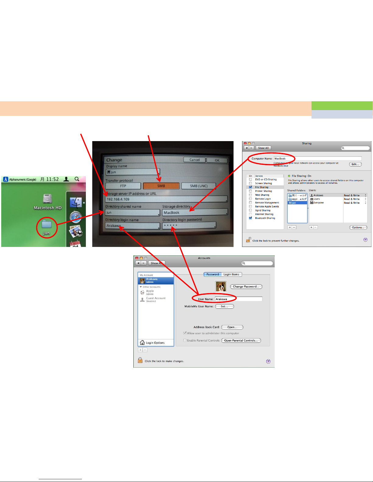
Remote Agent transfer specification
117
Remote Agent
DNS for Remote Agent setting
118
Remote Agent
Proxy for Remote Agent setting
119
Remote Agent
Send error history (REv data)
120
Remote Agent
Data list of RISO Remote Agent (REv exchange tool)
121
Paper jam
X02-1101 (Paper catch on the paper gate)
122
Paper jam
X02-1101/W56-1300/S98-0114/Z-folding
123
Paper jam
X04-1060 X05-1080 (Paper jam around upper transfer)
124
Paper jam
X06-1062, X06-1081, X07-1082 (Paper jam around switch back)
125
Paper jam
W24-1150 (Face down tray full) at installation
126
Paper jam
W24-1150 (Face down tray full) few months later after the
installation
127
Paper jam
W24-1150/X28-1084 (Individual face down ejection speed
adjustment)
128
Paper jam
Dog ear
129
Paper jam
Check points for dog ear problem
130
Paper jam
X14-1102 (Double feed)
131
Paper jam
X17-3140 (Paper jam in interface module)
132
Paper jam
X02-1058 (Paper bent at 6cm from the top edge)
133
Paper jam
X01-1058, Paper tear, dog ear
134
Paper jam
Compatibility of transfer pressure rollers
135
Paper jam
Compatibility of transfer motor (The vertical motor and the right
ejection motor
136
Paper jam
X03-1065 (Paper jam in the FU paper ejection unit)
137
Paper jam
Upper limit position for standard feed tray (X14-1102-1 Double
feed)
138
Paper jam
Replacement procedure for the upper limit actuators of multi
tray
Index3
4
139
Paper jam
S10-1031/1032/1033Tray elevation motor lock
140
Paper jam
Noise from the upper transfer unit
141
Paper jam
X12-1055 Gear slip
142
Image problem
CCD off mode
143
Image problem
W68-0245/W73-1303/I08-0229 BP Belt stain detection
144
Image problem
Misty image at top of paper
145
Image problem
White line
146
Image problem
Head cleaning point using cleaning liquid
147
Image problem
Image problem for Y direction
148
Image problem
Envelope print quality
149
Image problem
Ink drip down on the BP belt after head cleaning
150
PCB
PCBs compatibility
151
PCB
Swap second hand HDD or Engine PCB
152
PCB
Swap HDD or Engine PCB (Compatibility)
153
PCB
Matching between HDD, Engine PCB and Control card
154
PCB
Firmware compatibility
155
PCB
S98-0022 (PMS and Engine PCB Communication error)
156
PCB
S98-0022-3 S98-0018-2
157
PCB
S99-0246 S94-19xx (Engine PCB replacement)
158
Installation
Efficient installation
159
Installation
Configuration at the installation
160
Installation
Come off white arm of the maintenance unit at the installation
161
Electrical problem
S99-0006/0166,S98-0036
162
Electrical problem
Check points for wire harness for electrical problems
163
Electrical problem
Check points for Offset stacking tray installation
164
Electrical problem
Jobs stop as Idle status in the Active tab
165
Electrical problem
S35-2060, S96-1207, S98-0100-3, S98-0101-3
166
Electrical problem
S35-2057/2079/2081/2082/2083/2084 S36-2080
167
Electrical problem
S99-0152-06

5
Index4
168
Electrical problem
S98-0110-1
169
Electrical problem
USB function unable
170
Scanner
U03-43xx (Scanner FB error) U04-4430 (Scanner AF error)
171
Ink pan
Rubber tube protection in the area with high Ozone level

1, Create the share folder on the desktop of your computer or share server
2, Set up the data directory in the Admin mode Settings=>Scanner data directory=>Add
Share folder name
IP address of the computer
Domain name¥Login name
Scan to share folder (SMB)
When you set up the share folder on the computer which is used fixed IP address, you can use SMB for data directory.
Login password of this computer
If used
6
Function
Scanner

1, Create the share folder on the desktop of your computer or share server
2, Set up the data directory in the Admin mode Settings=>Scanner data directory=>Add
Domain name¥Login name
Scan to share folder (SMB UNC)
When you set up the share folder on the computer which is used DHCP, you should use the SMB UNC for this function.
Login password of this computer
If used
¥¥ Computer name¥Share folder name
You can check it by
Control panel=>System=>Computer name
on the computer
Function
Scanner
7

Create the share folder on the Mac OS10.5/10.6
8
1. Create a folder
4. Add the folder
5. Check the share users if Everyone is
included. Then press the Options
6. Tick the SMB function and the
Login account
Function
Scanner

Set up Scan to folder function for Macintosh share folder
9
Share folder name
Computer name
Login name and Password
IP address for the Mac Select [SMB]
Function
Scanner

Scan to PC
2,Press the OK button 3,Select the Networked computer
4,Directory will be changed
to computer name
5,After scanning, the scan data will
be saved into the share folder soon
1,Press the Scanner button
If the scan direction setting is not
correct, W60 error will be displayed.
You can register the scan data
directory as default setting by Admin
mode or registered user login.
Function
Scanner
10

Scan to e-mail
Regarding the Scan to Mail
Especially when the customer uses SMTP authentication on the mail server, it is better to ask them to set up.
For this setting, you can normally confirm it from the
mailer (Mail application) on the client computer.
For the below setting, you need to ask the
network environment of your customer
You need to ask to customer
Basically it is 25
If used
Function
Scanner
11

Scanning image direction Function
Scanner
Original
Scanning result (NG)
Scanning
direction
selected
Scanning result (OK)
selected
12

Sort printing with FB scanning Function
Scanner
When you make some copies from the Flatbed with some pages original, you need to change the Collate function
confirmation screen.
Scan from the FB: Auto collate means group printing
Scan from the AF: Auto collate means sort printing
confirmation screen will display after each page
scanning
In the function tab
13

IC card activation
Specification
ISO14443 TypeA TypeC (Mifare/Felica)
Up to 300 users
Set up procedure
1) Perform the key code by test mode 716/717/718
2) Press the Admin button, then the machine will request the Admin IC card
3) Set the Admin IC card on the reader and press the setting button
4) In the Login setting, you should change the copy mode and the scan mode to
5) Next you can add some users in the user setting as IC card users
6) Each users can change the default copy and scan screen individually
Function
IC card
14

Cancel the IC card function
When you need to cancel the IC card function, if amount of the following test-
function will disable.
After re-enter the test-mode, the registered IC card information will return again without re-enter
716 to “0”
717 to “0”
718 to “0”
Function
IC card
15

Individual touch panel setting
When the IC card reader is installed, the machine can set up individual default screen for each IC
card (each user)
Before individual setting, you must switch the Login setting to in Admin mode
1) Login setting to “Required”
2) Login as user and click the
function tab
3) You can see the “Save as
default” button in the “Check
setting” key
Function
User setting
16

Save as default setting for all users
Log in as Admin
Set up the functions as default setting
Select the function tab
Select the check setting button
Press the Save as default button
Then the default screen will save for all users
When you want to save individually, IC card reader and Login setting
are needed.
Function
User setting
17

User setting data upload/download
1) Download the CSV file from RISO console as Admin mode (Write CSV file button)
2)
3) Add or change the data, after that save as text data.
4) Change the extension code from .TXT to CSV.
5) Upload the CSV file from RISO console as Admin mode (Read CSV file button)
Download to PCUpload to ComColor
(Over write)
Function
User setting
18

Retrieve the common touch panel setting for each IC card user Function
User setting
When IC card users are registered as login required, all IC card user can set up own screen setting individually. If
the Admin has set up the recommend setting as default screen, all user can download this setting in each user
screen.
Admin setting IC card user setting
1) Login as Admin
2) Change the setting
3) Save as default
4) Login as user
5) Open the function tab
6) Press the Initialize button
7) Change the setting as
Admin default easily
19

Confirm the current counter for each user
When print limitation function is used, each user can find the own current counter.
1) Login as User
2) Press the meter reading button
3) You can see it in the Limit tab
B/W print: 2000
Colour print: 500
B/W copy: 1000
Colour copy: Prohibited
20
Function
User setting
Table of contents
Other Riso Printer manuals

Riso
Riso ComColor 9150 User guide

Riso
Riso VALEZUS T1200 User manual

Riso
Riso MZ970 User manual

Riso
Riso ComColor GL Series User manual

Riso
Riso HC5000T User manual

Riso
Riso GOCCOPRO QS200 User manual

Riso
Riso HC FINISHER Service manual

Riso
Riso Comcolor X1 Series User manual

Riso
Riso MZ 10 Series User manual

Riso
Riso CV1200W User manual

Riso
Riso GOCCOPRO QS2536 User manual

Riso
Riso HC5500 User manual

Riso
Riso MZ870 User manual

Riso
Riso HC5500 User manual

Riso
Riso HC Series Operating instructions

Riso
Riso Comcolor X1 Series User manual

Riso
Riso VALEZUS T2100 User manual

Riso
Riso KZ30 User manual

Riso
Riso GOCCOPRO QS200 User manual

Riso
Riso SF EII Series User guide