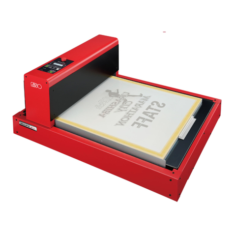
Riso GOCCOPRO 100 User manual

User’ s Guide
053-36001
053-36003
Printed in Japan
2020/2

Digital Screen Maker
Model: GOCCOPRO 100
The user iscautioned that unauthorized changesor modificationsnot approved could void the
user'sauthority to operate the equipment.
NOTE: Thisequipment hasbeen tested and found to comply with the limitsfor a Class B digital
device, pursuant to part 15 of the FCC Rules. These limitsare designed to provide reasonable
protection against harmful interference in a residential installation. Thisequipment generates,
usesand can radiate radio frequency energy and, if not installed and used in accordance with the
instructions, may cause harmful interference to radio communications. However, there isno
guarantee that interference will not occur in a particular installation. If thisequipment doescause
harmful interference to radio or television reception, which can be determined by turning the
equipment off and on, the user isencouraged to try to correct the interference by one or more of
the following measures:
- Reorient or relocate the receiving antenna.
-Increase the separation between the equipment and receiver.
- Connect the equipment into an outlet on a circuit different from that to which the receiver is
connected.
-Consult the dealer or an experienced radio/TV technician for help.
ThisClass B digital apparatus complieswith Canadian ICES-003.
Cet appareil numerique de la classe B est conforme a la norme NMB-003de Canada.
Perchlorate Material-special handling may apply,
See www.dtsc.ca.gov/hazardouswaste/perchlorate
Thisproduct may contain certain substanceswhich are restricted when disposed.
Therefore, be sure to consult your contracted service dealer.
MASCHINENLÄRMINFORMATION
Maschinenlärminformations-Verordnung 3. GSGV:
Der höchste Schalldruckpegel beträgt 70 dB(A) oder weniger gemäß EN ISO 7779.
Hinweis:
DasGerät ist nicht für die Benutzung am Bildschirmarbeitsplatz gemäss BildscharbV vorgesehen.

1
f
Thisguide containsinstructionsfor basic operation of the machine, precautionson
use, methodsfor handling and replacing consumables, and a troubleshooting guide.
Carefully read the guide before using the machine.
Also read thisguide if youhave any question during use and whenever it isnecessary, and make use of it with the machine
for many yearsto come.
ALL SPECIFICATIONS ARE SUBJECT TO CHANGE WITHOUT NOTICE.
Reproduction or copying of thisguide or any partswithout permission isstrictly prohibited.
Although every effort hasbeen made to ensure that the contentsof thisguide are error-free, please contact us if younotice
any errorsor other pointswhich should be brought to the company'sattention.
●and RISORINC are trademarksor registered trademark of RISO
KAGAKU CORPORATION in the United Statesand other countries.
●Microsoft, Windowsand WindowsVista are either registered trademarksor trade-
marksof Microsoft Corporation in the United Statesand/or other countries.
●Other corporate namesand/or trademarksare either registered trademarksor
trademarksof each company, respectively.
●The screensand content appearing in thisguide may differ from the actual prod-
uct.
●The screensand messagesappearing in proceduresmay differ depending on the
type of the computer and the application (thisguide usesscreensof Windows7).
Riso KagakuCorporation London Office, 610 Centennial Park, Centennial Avenue, Elstree, Herts, WD6 3TJ U.K.
© Copyright 2020 RISO KAGAKU CORPORATION
Thisbooklet isprinted using the RISO ComColor and bound using the Perfect Binder.
The sidesare trimmed afterwards.
Welcome to GOCCOPRO 100
Thank youfor purchasing thismachine.
Thismachine isa digital screen maker that can be easily operated.
Thisguide isintended for use by RISO, itsauthorized dealersand purchasersof the equipment described herein. While
every effort hasbeen made to ensure the accuracy of information contained in thisguide, RISO, itsauthorized dealers
and their employeesshall not be held responsible for any inaccuraciesit may contain.

2
Easy Operation
●Since the original data iscreated on your computer,
youcan produce an imaged screen just like using with
a printer.
●Automatic screen making that doesnot require emul-
sion coating, exposure or washout.
●The imaged screen isautomatically cut to the desig-
nated size.
Useful Functions
●Yo ucan set a margin even immediately before making
a screen.
●Yo ucan easily reproduce an imaged screen of the last
output job.
High-resolution Perforation at
600 dpi ×600 dpi
●Since original data created on a computer are directly
transferred onto a screen, fine charactersand lines
can be reproduced with high definition.
●Yo ucan adjust the image quality by using the printer
driver.
Supports Macintosh
●To connect the machine to your Macintosh, optional
"RISO GOCCOPRO Printer Driver for Macintosh" and
"RISO Network Card" are required.
Space-saving Design
●A compact body that can be placed beside the desk.
Characteristics of This Product
Thismachine isa digital screen maker exclusively designed for RISO Digital Screen
Master. The imaged screen can be attached on your frame for use.
Screen reproduction / storage function
The last output job isstored in the machine until it
receivesthe new original data. If youwant to repro-
duce an imaged screen using the same original data
that youproduced in the last job, youcan reproduce it
by simply pressing the <STORAGE> Key on the
machine without transmitting the original data from
your computer again.
Every time new original data isreceived, the produced
and stored data in the machine will be erased. There-
fore, only the original data that yououtput in the last
job will alwaysbe used to reproduce an imaged
screen.
When youwant to repeatedly reproduce an imaged
screen, we recommend making the machine offline by
pressing the <ONLINE> Key in order to prevent the
machine from receiving new original data.
Turning off the power switch will also erase the stored
data.
Column

3
Indication of Precautions
The following iconsare used throughout the guide.
Indication of Descriptions of Operations and Functions
Descriptionsof functionsand operationsare indicated asfollows.
The Notation in This Guide
In thisguide, notationsare used in the following manner.
Ignoring thiswarning could cause death or serious injury.
Ignoring thiscaution could cause injury or damage to property.
Indicatesitemsthat require special attention or that are prohibited actions.
Read carefully and follow the directionsasinstructed.
Givesyouuseful information.
Indicatesa reference page.
1Preparations for Use for the First Time
25
5
Install a new Screen Master Roll.
6
1) Close the Screen Master Roll Holder.
2) Remove the wrapper.
7
1) Insert the leading edge of the Screen Master
Roll into its entrance under the Screen Master
Guide Flap until it stops.
2) If the screen master is loose, turn the flange
at the right inward to rewind.
8
Close the Screen Making Unit.
9
Close the Screen Making Unit Cover.
Do not remove the wrapper yet.
mark must be seen on the left.
Do not remove
the wrapper.
If you cannot insert the leading edge of the
screen master well:
1) Turn the wheel beside the Screen Master
Guide Flap inward to raise the Screen Mas-
ter Guide Flap.
2) Pull out the Screen Master Roll up to the
line indicated by the arrows.
3) Close the Screen Master Guide Flap.
Screen Master Guide Flap
Flange
24
1
Turn on the machine.
2
Hold the Screen Making Unit Cover Handle and
open the cover.
3
Grasp the Screen Making Unit Open Lever and
open the Screen Making Unit
4
Open the Screen Master Roll Holder.
To replace the screen, remove the depleted Screen
Master Roll.
Setting a New Screen Master Roll
Set a Screen Master Roll in the machine.
If the <REPLACE MASTER> Indicator on the Control Panel is lit, also perform the fol-
lowing procedure to replace the screen master.
• For the Screen Master Roll, it is recommended to use the products
specified by Riso.
• Keep the power On while replacing the Screen Master Roll.
<REPLACEMASTER>Indicator
ON
Dispose the depleted Screen Master Roll
according to the disposal rule of your local
community.
see "Disposal of a Depleted Screen
Master Roll" on page 83
Chapter title
Operating procedure
An operating procedure is
described in steps. Follow
these stepsto perform oper-
ation.
Operation illustration
Showsa part related to the
operation described in the
respective step. A screen on
the Control Panel of the
machine or on the computer
isdisplayed.

4
Characteristics of This Product . . . . . . . . . . . . . . . . . . . . . . . . . . . . . . . . . . . . . . . 2
•Easy Operation . . . . . . . . . . . . . . . . . . . . . . . . . . . . . . . . . . . . . . . . . . . 2
•Useful Functions. . . . . . . . . . . . . . . . . . . . . . . . . . . . . . . . . . . . . . . . . . 2
• High-resolution Perforation at 600 dpi ×600 dpi . . . . . . . . . . . . . . . . . . 2
•SupportsMacintosh . . . . . . . . . . . . . . . . . . . . . . . . . . . . . . . . . . . . . . . . 2
• Space-saving Design . . . . . . . . . . . . . . . . . . . . . . . . . . . . . . . . . . . . . . . 2
The Notation in This Guide . . . . . . . . . . . . . . . . . . . . . . . . . . . . . . . . . . . . . . . . . . .3
Introduction
Safety Guide . . . . . . . . . . . . . . . . . . . . . . . . . . . . . . . . . . . . . . . . . . . . . . . . . . . . . . . 8
Installation . . . . . . . . . . . . . . . . . . . . . . . . . . . . . . . . . . . . . . . . . . . . . . . . . . . 8
Power Connection . . . . . . . . . . . . . . . . . . . . . . . . . . . . . . . . . . . . . . . . . . . . . 8
Ground Connection . . . . . . . . . . . . . . . . . . . . . . . . . . . . . . . . . . . . . . . . . . . . 8
Handling and Operation . . . . . . . . . . . . . . . . . . . . . . . . . . . . . . . . . . . . . . . . . . . . . .9
Operation Environment. . . . . . . . . . . . . . . . . . . . . . . . . . . . . . . . . . . . . . . . . . 9
Machine Handling. . . . . . . . . . . . . . . . . . . . . . . . . . . . . . . . . . . . . . . . . . . . . . 9
Locationsof Caution Labels. . . . . . . . . . . . . . . . . . . . . . . . . . . . . . . . . . . . . . 9
Precautionson Connection . . . . . . . . . . . . . . . . . . . . . . . . . . . . . . . . . . . . . 10
•Precautionsfor Connecting with the Power Supply . . . . . . . . . . . . . . . 10
• The Power Cord and an Extension Cable . . . . . . . . . . . . . . . . . . . . . . 10
• The Printer Driver. . . . . . . . . . . . . . . . . . . . . . . . . . . . . . . . . . . . . . . . . 10
•Precautionson the Connection with a Computer. . . . . . . . . . . . . . . . . 10
Precautionson Use . . . . . . . . . . . . . . . . . . . . . . . . . . . . . . . . . . . . . . . . . . . 11
•Precautionson the Handling of the Machine . . . . . . . . . . . . . . . . . . . . 11
• Storing the Screen Master . . . . . . . . . . . . . . . . . . . . . . . . . . . . . . . . . . 11
• How to Produce an Imaged Screen from Original Data
other than of Standard Size . . . . . . . . . . . . . . . . . . . . . . . . . . . . . . . . . 11
• The Image Area . . . . . . . . . . . . . . . . . . . . . . . . . . . . . . . . . . . . . . . . . . 11
• The Margin Size Required for Screen Making . . . . . . . . . . . . . . . . . . . 12
MaterialsNot to Be Printed. . . . . . . . . . . . . . . . . . . . . . . . . . . . . . . . . . . . . . 13
Names and Functions of Parts . . . . . . . . . . . . . . . . . . . . . . . . . . . . . . . . . . . . . . .14
Main unit . . . . . . . . . . . . . . . . . . . . . . . . . . . . . . . . . . . . . . . . . . . . . . . . . . . . 14
Control Panel . . . . . . . . . . . . . . . . . . . . . . . . . . . . . . . . . . . . . . . . . . . . . . . . 16
Basic Process from Screen Making to Printing . . . . . . . . . . . . . . . . . . . . . . . . . 18
Table of Contents

Table of Contents
5
1Preparations for Use for the First Time
Setting a New Screen Master Roll . . . . . . . . . . . . . . . . . . . . . . . . . . . . . . . . . . . . 20
Installing the Printer Driver . . . . . . . . . . . . . . . . . . . . . . . . . . . . . . . . . . . . . . . . . . 22
USB cable Connection . . . . . . . . . . . . . . . . . . . . . . . . . . . . . . . . . . . . . . . . . 22
• Before Installation . . . . . . . . . . . . . . . . . . . . . . . . . . . . . . . . . . . . . . . . 22
•Installation Procedure . . . . . . . . . . . . . . . . . . . . . . . . . . . . . . . . . . . . . 23
• Creating a USB Port . . . . . . . . . . . . . . . . . . . . . . . . . . . . . . . . . . . . . . 29
• USB Device Association . . . . . . . . . . . . . . . . . . . . . . . . . . . . . . . . . . . 30
Network Connection (LAN). . . . . . . . . . . . . . . . . . . . . . . . . . . . . . . . . . . . . . 31
• Before Installation . . . . . . . . . . . . . . . . . . . . . . . . . . . . . . . . . . . . . . . . 31
2How to Produce an Imaged Screen
1)Preparing the Machine . . . . . . . . . . . . . . . . . . . . . . . . . . . . . . . . . . . . . . . . . . . . 34
2)Transmitting Original Data from the Computer . . . . . . . . . . . . . . . . . . . . . . . . 35
Detailsof Printer Driver Settings. . . . . . . . . . . . . . . . . . . . . . . . . . . . . . . . . 36
3) Selecting a Frame . . . . . . . . . . . . . . . . . . . . . . . . . . . . . . . . . . . . . . . . . . . . . . .40
Selecting a Frame and Starting Screen Making . . . . . . . . . . . . . . . . . . . . . . 40
3Settings for More Convenient Use
Settings that Can be Made in Custom Setting Mode . . . . . . . . . . . . . . . . . . . . . 46
How to Make Settings in Custom Setting Mode . . . . . . . . . . . . . . . . . . . . . . . . . 49
How to Register a Frame . . . . . . . . . . . . . . . . . . . . . . . . . . . . . . . . . . . . . . . . . . . . 50
How to Set the IP Address . . . . . . . . . . . . . . . . . . . . . . . . . . . . . . . . . . . . . . . . . . .52
Initializing the Custom Setting Mode /
the Network Card . . . . . . . . . . . . . . . . . . . . . . . . . . . . . . . . . . . . . . . . . . . . . . . . . . 54
4Maintenance
Maintenance . . . . . . . . . . . . . . . . . . . . . . . . . . . . . . . . . . . . . . . . . . . . . . . . . . . . . . 58
Cleaning . . . . . . . . . . . . . . . . . . . . . . . . . . . . . . . . . . . . . . . . . . . . . . . . . . . . . . . . . 59
Thermal Print Head . . . . . . . . . . . . . . . . . . . . . . . . . . . . . . . . . . . . . . . . . . . 59
Cleaning the Main Unit Exterior . . . . . . . . . . . . . . . . . . . . . . . . . . . . . . . . . . 60

6
5Troubleshooting
When an Error Indicator Lights . . . . . . . . . . . . . . . . . . . . . . . . . . . . . . . . . . . . . . .62
Troubleshooting (Tips) . . . . . . . . . . . . . . . . . . . . . . . . . . . . . . . . . . . . . . . . . . . . . 65
Actionsto Be Taken on the Main Unit . . . . . . . . . . . . . . . . . . . . . . . . . . . . . 65
Actionsto Be Taken on the Printer Driver . . . . . . . . . . . . . . . . . . . . . . . . . . 67
When the Image isNot Correctly Produced onto the Screen. . . . . . . . . . . . 68
Appendix
Registering Original Size . . . . . . . . . . . . . . . . . . . . . . . . . . . . . . . . . . . . . . . . . . . . 72
Manually Installing the Printer Driver . . . . . . . . . . . . . . . . . . . . . . . . . . . . . . . . . . 73
For Windows10 . . . . . . . . . . . . . . . . . . . . . . . . . . . . . . . . . . . . . . . . . . . . . . 73
• USB Connection . . . . . . . . . . . . . . . . . . . . . . . . . . . . . . . . . . . . . . . . . 73
• Network Connection (LAN) . . . . . . . . . . . . . . . . . . . . . . . . . . . . . . . . . 74
For Windows8.1 / Windows8 . . . . . . . . . . . . . . . . . . . . . . . . . . . . . . . . . . . 75
• USB Connection . . . . . . . . . . . . . . . . . . . . . . . . . . . . . . . . . . . . . . . . . 75
• Network Connection (LAN) . . . . . . . . . . . . . . . . . . . . . . . . . . . . . . . . . 76
For Windows7 . . . . . . . . . . . . . . . . . . . . . . . . . . . . . . . . . . . . . . . . . . . . . . . 77
• USB Connection . . . . . . . . . . . . . . . . . . . . . . . . . . . . . . . . . . . . . . . . . 77
• Network Connection (LAN) . . . . . . . . . . . . . . . . . . . . . . . . . . . . . . . . . 78
For WindowsXP. . . . . . . . . . . . . . . . . . . . . . . . . . . . . . . . . . . . . . . . . . . . . . 79
• USB Connection . . . . . . . . . . . . . . . . . . . . . . . . . . . . . . . . . . . . . . . . . 79
• Network Connection (LAN) . . . . . . . . . . . . . . . . . . . . . . . . . . . . . . . . . 80
For WindowsVista . . . . . . . . . . . . . . . . . . . . . . . . . . . . . . . . . . . . . . . . . . . . 81
• USB Cable Connection . . . . . . . . . . . . . . . . . . . . . . . . . . . . . . . . . . . . 81
• Network Connection (LAN) . . . . . . . . . . . . . . . . . . . . . . . . . . . . . . . . . 82
Uninstalling the Printer Driver . . . . . . . . . . . . . . . . . . . . . . . . . . . . . . . . . . . . . . .83
In Case of Using the Uninstaller . . . . . . . . . . . . . . . . . . . . . . . . . . . . . . . . . . 83
In Case of Manually Uninstalling the Printer Driver . . . . . . . . . . . . . . . . . . . 84
• For Windows10 / Windows8.1 / Windows8 / Windows7 . . . . . . . . . . 84
• For WindowsXP . . . . . . . . . . . . . . . . . . . . . . . . . . . . . . . . . . . . . . . . . 84
• For WindowsVista . . . . . . . . . . . . . . . . . . . . . . . . . . . . . . . . . . . . . . . . 85
Consumables and Options . . . . . . . . . . . . . . . . . . . . . . . . . . . . . . . . . . . . . . . . . . 86
Screen Master Roll . . . . . . . . . . . . . . . . . . . . . . . . . . . . . . . . . . . . . . . . . . . . 86
Options. . . . . . . . . . . . . . . . . . . . . . . . . . . . . . . . . . . . . . . . . . . . . . . . . . . . . 86
Disposal of a Depleted Screen Master Roll . . . . . . . . . . . . . . . . . . . . . . . . . 86
Specifications . . . . . . . . . . . . . . . . . . . . . . . . . . . . . . . . . . . . . . . . . . . . . . . . . . . . . 87
Index . . . . . . . . . . . . . . . . . . . . . . . . . . . . . . . . . . . . . . . . . . . . . . . . . . . . . . . . . . . . 89

Introduction
This section describes matters you should know before
using the machine and precautions you should follow.

8
●Place the machine on a flat and stable surface (maxi-
mum of 3/8" / 10 mm differential allowed). Injury might
occur if the machine falls.
●Keep the machine away from dusty or humid environ-
ments. Failure to do so may result in fire.
• This machine is designed to be installed in a fixed
location.
• Avoid installing the machine in the locations listed
below.
Failure to observe this precaution may result in mal-
function or accident.
• Locations with exposure to direct sunlight and
bright locations such as that close to windows (if
such locations are unavoidable, shield windows with
curtains or the like)
• Locations subject to sudden temperature changes
• Hot and humid locations or cold and dry locations
• Locations with fire or heat, and locations directly
exposed to cold air, hot air, or radiant heat
• Locations with poor ventilation
• Locations with much dust
●Do not overload the electrical outlet or
extension cord, nor damage the power
cord by placing heavy objectson it or pull-
ing or bending it. Thiscan result in fire or
electric shock.
●Depending on the voltage used, the specificationsof
available power cordsand extension cordsvary. Erro-
neously using a power cord or extension cord may
result in fire or electric shock.
• The length of the power cord and the extension cord
must be within 14.75 feet / 4.5 m and 15 feet / 5 m,
respectively.
• If the Voltage Changeover Switch isin the 220 V to
240 V position when using the machine, use a cable
with specificationsof 250 V/5 A or more, and make
sure itslength iswithin 15 feet / 5 m.
• If the Voltage Changeover Switch isin the 100 V to
120 V position when using the machine, use a cable
with specificationsof 125 V/8 A or more, and make
sure itslength iswithin 15 feet / 5 m.
●Do not plug or unplug the power cord if your handsare
wet. Thiscan result in electric shock.
●Do not pull the power cord but hold the plug itself
when unplugging it. Thiscan damage the cord and
result in fire or electric shock.
●If the machine isnot used for a long period such as
holidays, be sure to disconnect the power plug from
the outlet for safety.
●Pull out the power plug from the electrical outlet more
than once a year and clean the prongsof the plug and
their surroundings. Dust collected on these areascan
result in fire
●Be sure to insert the power plug with a ground con-
ductor into the wall outlet with a ground receptacle.
Do not use the machine if it isnot grounded. It may
result in fire or electric shock.
Safety Guide
Thissection describesmattersyoushould know before using the machine, including
precautionson the location for installing the machine and on the power supply.
Be sure to read thissection before using the machine.
Installation
Power Connection
Ground Connection
Introduction
9
• The appropriate environment requirements
are as follows.
• Temperature range: 59°F to 86°F / 15°C to
30°C
• Humidity range: 40% to 70%
(no condensation)
●Do not place water containersor metallic objectson
the machine. Fire or electric shock may occur if water
or metallic objectsfall into the machine.
●Do not use a combustible spray and flammable sol-
vent near the machine. If sprayed gasand the flamma-
ble solvent contactselectronic componentsinside the
machine, fire or electric shock might occur.
●Do not insert any metallic or flammable substance into
the machine through any opening. Thiscan result in
fire or electric shock.
●Do not remove machine covers. Exposing internal
partsmay result in electric shock.
●Do not disassemble or rebuild the machine
by yourself. Thiscan result in fire or elec-
tric shock.
●If the machine emitsexcessive heat,
smock or foul odor, immediately turn off
the POWER, unplug the power cord and
contact your dealer. Failure to do so can
result in fire or electric shock.
●If something dropsinside the machine,
immediately turn off the POWER, discon-
nect the power plug from the outlet, and
contact your dealer. Failure to do so can
result in fire or electric shock.
●Never put your finger into an opening near the Imaged
Screen Outlet. Thismay cause injury.
●If lifting or moving the machine, be sure to hold the
bottom of the main unit. Holding the upper part of the
main unit may cause it to fall and result in injury.
●Do not directly touch the thermal print head with your
fingers. The thermal print head may be heated and
cause burns.
Thismachine hassome caution labelsto ensure safe
operation. Follow the indicationsof those labelsand use
thismachine safely.
Handling and Operation
Operation Environment
Machine Handling
40%
70%
Locations of Caution Labels

10
Precautions for Connecting with the
Power Supply
●
To prevent loose connection of the power
plug, securely connect the plug to the outlet.
●Install the machine near the outlet.
●Thismachine isequipped which the "Auto Power off"
function with automatically turnsoff the POWER of the
machine when it hasnot been used for a certain
period with the POWER turned on.
"Settings for More Convenient Use" on page 45
●Do not touch the Voltage Changeover Switch located
on the left of the Power Connector (AC inlet). If intend-
ing to change the power supply, contact your dealer.
Erroneously changing the voltage may cause failure.
The Power Cord and an Extension
Cable
●If the Voltage Changeover Switch isin the 100 V to
120 V position when using the machine, use cable
with specification of 125 V/8 A or more.
●If the Voltage Changeover Switch isin the 220 V to
240 V position when using the machine, use a cable
with specificationsof 250 V/5 A or more.
The Printer Driver
Thisprinter driver isdesigned for screen making by trans-
mitting original data from your computer.
The printer driver iscontained in the included CD-ROM.
When making a screen master for the first time, it isnec-
essary to install the printer driver.
Thisprinter driver supportsthe following OS:
• Windows®10 (32-bit/64-bit)*
• Windows®8.1 (32-bit/64-bit)*
• Windows®8 (32-bit/64-bit)*
• Windows®7 (32-bit/64-bit)
• Windows®XP (32-bit)
• WindowsVista®(32-bit/64-bit)
* Only compatible with desktop app
Precautions on the Connection with a
Computer
●Before using the machine, be sure to install the printer
driver from the included CD-ROM.
●Thismachine must be connected with a computer via
a commercially available USB cable (10 feet / 3m or
less, compliant with Hi-Speed USB). For details, see
"USB cable Connection" on page 22.
Precautions on Connection
Do not connect the machine with the com-
puter before installing the printer driver.
If the optional network interface card "RISO Network
Card" isinstalled, the machine can be connected
with a Macintosh computer. For details, see the
User'sGuide of RISO Network Card.

Introduction
11
Precautions on the Handling of the Machine
●Do not open the Screen Making Unit Cover or move
the machine during operation.
●Gently open or close the Screen Making Unit Cover
and the Imaged Screen Tray.
●Do not place heavy objectson the machine. The
objectsmight fall and cause injury.
●Thismachine hasprecision partsand driving mecha-
nism. Do not handle the machine in other way than
described in thisguide.
Storing the Screen Master
●Properly store the screen master. Avoid storing it in
the following places.
• Locationswith exposure to direct sun-
light and bright locationssuch asthat
close to windows(if such locationsare
unavoidable, shield windowswith cur-
tainsor the like)
• Locationssubject to sudden temperature changes
• Hot and humid locationsor cold and dry locations
How to Produce an Imaged Screen from
Original Data other than of Standard Size
To specify an original size other than the standard size,
be sure to register the original size other than the stan-
dard size set for the dedicated printer driver in advance.
"Registering Original Size" on page 72
The Image Area
The relationship between the direction of the original data
created on the computer and the direction of the original
data transferred onto a screen isasfollows.
Precautions on Use
Do not turn off the POWER or disconnect the
power plug during operation.
For screen making, a Screen Master with the
same length as the used frame is used.
The original data is to be placed in the center of the
frame used regardless of the size when it was created.
Original data
Length
Width
Original data
transmitted
Screen master Length
Width
Screen master
feed direction
Screen master

12
Image Area
• Minimum Image Area: 0.39" (width) ×0.39" (length)/
10 mm (width) ×10 mm (length)
•
Maximum Image Area
: 11.69" (width) ×31.50" (length)/
297 mm (width)
×
800 mm (length)
If the size of the original data exceedsthe maximum width
11.69" / 297 mm of the image area, any part outside the
image area will not be transferred to the screen.
The Margin Size Required for
Screen Making
Since the original data isto be placed in the center of the frame
used when an imaged screen isproduced, marginsare left on
the Top and End sidesof the original data. Marginsare required
on both the Top and End sidesasspacesfor attaching the
imaged screen to the frame and apply inks.
The margin size isautomatically calculated based on the size
or length of the frame used and the size of the original data.
The size of the margin required for each frame type isasindicated in the table below.
The frame used can be selected using the <FRAME SELECT> Key on the Control
Panel.
If the margin size isinsufficient during screen making, an <LENGTH> error occurs
and an imaged screen cannot be produced.
"When an Error Indicator Lights" on page 62
Minimum
Width:
11.69˝ / 297 mm
Length: 31.50˝ / 800 mm
Width:
0.39˝ / 10 mm
Length:
0.39˝ / 10 mm
〜
Maximum
Data transferred onto a screen
Data not transferred onto a screen
Maximum image area
31.50
˝
/ 800mm
11.69
˝
/
297mm
Screen master width
12.60
˝
/ 320mm
Frame length
(screen master length)
Margin size
on the End side*
Original data length
Margin size
on the Top side*
Frame length (screen length)
Screen master
feed direction
* The margin sizeson the Top and End sidescan be
arbitrarily set.

Introduction
13
Do not use the machine in any manner which violatesthe law or infringeson estab-
lished copyrights, even when making copiesfor personal use. Consult your local
authoritiesfor further details. In general, use discretion and common sense.
Frame type Margin size on the
Top side
Margin size on the
End side Method for margin size setting
Frame 1 - 5 2.4" / 60 mm or
more
2.4" / 60 mm or
more
The margin size isautomatically calculated from the
frame length and the original size. Youcannot arbi-
trarily set the margin size.
The frame length isset in Custom Setting mode.
"How to Register a Frame" on page 50
MINIMUM
(Minimum Margin)
2.4" / 60 mm fixed 0.6" to 1.2"
/ 15 mm to 30 mm
Reduce the margin on the End side. The margin is
set in Custom Setting mode.
"How to Register a Frame" on page 50
MANUAL
(Arbitrary Margin)
2.4" to 8.0"
/ 60 mm to 200 mm
0.6" to 8.0"
/ 15 mm to 200 mm
Select the Top side or the End side of the original
data using the <MANUAL> Key, and enter an arbi-
trary margin size using the 0 to 9 Keys.
When Making a Screen from a Landscape-oriented Origi-
nal:
Pay attention to the size of the original data. Any part outside
the image area will not be transferred onto the screen. If the
left or right end of the original isoutside the image area, take
the following action.
• Perform "Original size entry" of the printer driver to register
an original size with the length and width of the original
interchanged in advance.
"Registering Original Size" on page 72
• Rotate the original by 90°using a function of the application
software before making a screen.
Setting of the application Imaged screen
Column
Materials Not to Be Printed

14
1) Control Panel
Performsoperationssuch asstarting screen making and
changing settingsof the machine.
"Control Panel" on page 16
2) Imaged Screen Tray
Receivesan imaged screen.
To store it in the machine, tilt it toward the Imaged Screen
Outlet side.
3) Imaged Screen Outlet
Ejectsan imaged screen. An imaged screen iscut to a
designated size.
4) Ethernet Port
Used when adding the optional "RISO Network Card".
5) USB Port
Connect a computer to thisport using a commercially avail-
able USB cable.
"USB cable Connection" on page 22
6) Screen Making Unit Cover
Opensto allow screen master replacement and mainte-
nance of the machine interior.
"Setting a New Screen Master Roll" on page 20
Names and Functions of Parts
Thissection describesthe namesand functionsof partsof the machine.
Main unit
Imaged Screen Outlet side
1)
2)
3)
4)
5)
6)
Attaching / Removing the Imaged Screen Tray
The Imaged Screen Tray can be removed.
●How to Attach It
Fit the 2 fitting holesof the Imaged Screen Tray
over the 2 projectionsat the Imaged Screen Outlet.
●How to Remove It
Lift the Imaged Screen Tray to remove it.

Introduction
15
7) Screen Making Unit Open Lever
To open the Screen Making Unit for screen master
replacement or the like, hold thislever to release the lock.
8) Thermal Print Head
Perforatesa screen according to the original data.
9) Screen Making Unit
10
) Screen Master Guide Flap
11
) Screen Master Roll Holder
Securesa Screen Master.
12
) Screen Master Roll
13
) Power Connector
14
) Voltage Changeover Switch
Yo ucan switch the input voltage between 100 - 120V and
220 - 240V according to the service environment.
If switching the voltage, contact your dealer.
15
) Handle
Hold it to open/close the Screen Making Unit Cover.
16
) Power Switch
Power Switch Side
7)
8)
9)
10)
11)
12)
13)
14)
15)
16)

16
From the Control Panel, youcan start screen making and change frame size and mar-
gin settings.
Lighting and blinking of the indicatorswill also let youknow the conditionsof the machine.
1) <STORAGE> Indicator (Reproduction Indicator)
Lightswhen original data transferred onto a screen is
stored in the machine.
2) <STORAGE> Key (Reproduction Key)
Pressing it when the <STORAGE> Indicator islighting will
reproduce a screen of stored data.
"
Screen reproduction / storage function
" on
page 2
3) <ALL RESET> Key
Used to return the setting made on the Control Panel to the initial
set value, or cancel trouble after troubleshooting iscompleted.
4) <STOP> Key
Stopsthe operation being executed.
Pressing and holding it (from more than one second) dur-
ing screen making will interrupt screen making.
5) <ENTER> Key
Used when making settingsin Custom Setting mode or fixing
a margin size.
"Settings that Can be Made in Custom Setting
Mode" on page 46
6) <START> Indicator
Lightswhen the received original data hasbecome ready
for screen making.
7) <START> Key
Startsscreen making.
8) <C> Key
Deletesthe value indicated on the display.
Control Panel
13)
11) 12) 10) 9) 6) 7) 4)
14) 15) 16) 17)
1)
18)
5)
2)
3)
8)

Introduction
17
9) 0 to 9 Keys
Enter numerical values.
10
) <inch / mm> Indicator
Indicatescurrently selected unit. The unit can be changed
in Custom Setting mode.
"Settings that Can be Made in Custom Setting
Mode" on page 46
11
) <ONLINE> Indicator
Indicatesthe state of connection with the computer.
Lit:
Can receive original data from the computer (online)
Not lit: Cannot receive original data (offline)
Blinking:Receiving original data
12
)<ONLINE>Key
Switchesbetween online and offline.
13
) <FRAME SELECT> Key
Select a frame to be used from registered frames1 to 5,
MINIMUM or MANUAL. Each time youpress the ▲/ ▼
key, the frame ischanged, and the indicator for the
selected frame lights. The frame size must be registered
in advance.
"How to Register a Frame" on page 50
14
) <MANUAL> Key
When <MANUAL> isselected in <FRAME SELECT>, any
margin size can be set. Each time youpress the key, the
side (Top side / End side) where the margin size isset
switchesto the other. The margin size can be entered
from the 0 to 9 Keys.
15
) Check & Error Display
Showsthe location and type of error by lighting the
respective indicator.
"When an Error Indicator Lights" on page 62
16
)Display
Showsinformation such asnumerical valuesand frame
length entered in various settings, and an error number in
case of error.
17
) <CUSTOM SETTING> Indicator
Lightsin "Custom Setting mode" in which the initial set-
tingscan be changed.
18
) <CUSTOM SETTING> Key
Press it to enter or exit Custom Setting mode.
"How to Make Settings in Custom Setting
Mode" on page 49
Switching to offline while original data is being
received (<ONLINE> Indicator is blinking) or
when there is original data in the screen-making
queue (<START> Indicator is lit) will delete these
original data.
How to Use the Offline Mode
While the <ONLINE> Indicator islit, pressing the
<ONLINE> Key enablesyouto switch from online
mode (original data can be received from the com-
puter) to offline mode (original data cannot be received
from the computer).
Switch to offline mode in the following cases.
• Deleting original data erroneously transmitted from
the computer
• Repeatedly produced an imaged screen using "reproduc-
tion data" (preventsnew original data from being received)
If desiring to repeatedly produce an imaged screen
using reproduction data, perform the following steps.
1) Produce an imaged screen online.
2) Check that the <STORAGE> Indicator islit.
The original data used for screen making in step 1)
will be stored asreproduction data.
While an imaged screen isproduced on online mode
and another original data with the [Auto Screen Mak-
ing] issetting to [ON] in the printer driver isreceived,
the previous stored data may be erased.
3) Press the <ONLINE> key to switch to offline mode.
New original data will not be received until switch-
ing to online mode.
4) Press the <STORAGE> Key.
Reproduction data will be transferred onto a screen.
Column

18
Basic Process from Screen Making to Printing
The basic process from the screen making on the machine using original data created
on the computer to the printing isasfollows.
ThisUser'sGuide describesthe process until Step 4.
2
3
4
5
6
1
Print!
START!
ON!
Turning on the machine
"1)Preparing the Machine" on page 34
Creating original data on the computer, and
outputting the data (data transmission)
"2)Transmitting Original Data from
the Computer" on page 35
Pressing the <START> Key to start
screen making
"3) Selecting a Frame" on page 40
An imaged screen produced
Attaching an imaged screen to
the frame
Printing with ink suitable for
printed materials
The original data transmitted
from the computer to the
machine
Table of contents
Other Riso Printer manuals

Riso
Riso Comcolor Series Service manual

Riso
Riso ComColor GL Series User manual

Riso
Riso CV1200W User manual

Riso
Riso ComColor FT Series User manual

Riso
Riso VALEZUS T1200 User manual

Riso
Riso ComColor FW Series Original instructions

Riso
Riso ComColor FW Series User manual

Riso
Riso ComColor IS900C User manual

Riso
Riso HC Series Operating instructions

Riso
Riso SF Series User manual

Riso
Riso HC5500T User manual

Riso
Riso ComColor FT Series User manual

Riso
Riso RZ Series User manual

Riso
Riso KZ30 User manual

Riso
Riso Comcolor Series User manual

Riso
Riso 9050 User guide

Riso
Riso VALEZUS T2100 User manual

Riso
Riso SF EII Series User guide

Riso
Riso ComColor GD9630 User manual

Riso
Riso HC5500 User manual