manuals.online logo
Brands
  1. Home
  2. •
  3. Brands
  4. •
  5. Roger
  6. •
  7. IP Access Controllers
  8. •
  9. Roger CEB12 User manual

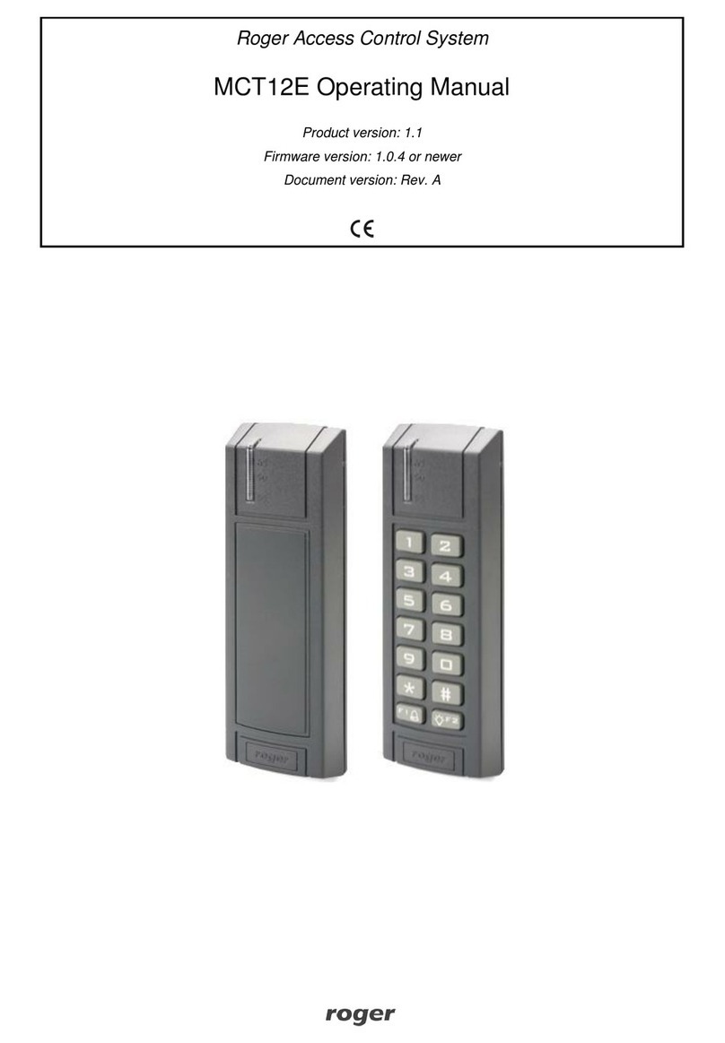
Roger CEB12 User manual

CEB12 Installation Manual.doc 2023-10-19
1/2
Roger Access Control System
CEB12 Installation Manual
Firmware version: 1.0.0.4
Hardware version: v1.0
Document version: Rev. B
DESIGN AND APPLICATION
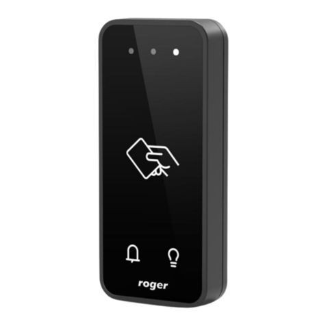
CEB12 is a contactless exit button which, after recognizing that the hand is
approaching the front panel, temporarily switches on its electrical output.
Basically, CEB12 has been designed to be used as a non-contact room exit
button, and it can perform this function via a master device (e.g. access
controller, intercom) or independently as standalone device. CEB12 can be
powered independently from dedicated 12V DC/AC voltage source or in series
with the energy receiver (electric strike), which it controls. The front panel of the
device is made of natural glass and can be cleaned with disinfectants.
CHARACTERISTICS
•Contactless exit button
•12 VDC/AC power supply or from door strike circuit
•Adjustable detection distance (approx. 7-14 cm)
•Adjustable output activation time 1-5s
•Transistor output 12VDC/1A
•Overload and overvoltage protection
•LED backlight
•Tamper contact
•Indoor operation only
•Glass front panel
•Surface mounting enclosure with dimensions 85x85x22 mm
•CE mark
INSTALLATION
Configuration of detection distance
CEB12 offers two levels of detections distance i.e. LOW and HIGH. The level is
selected with jumper on DISTANCE contacts.
Fig. 1 LOW detection distance
Fig. 2 HIGH detection distance
Configuration of output activation time
Output activation time for standalone operation is programmed with the
RELEASE TIME button. In order to program the time, press the button and hold it
down for the time for which the output is to be activated after detection of hand.
During programming, the RED LED indicator located in the center of the front
panel lights up. Time parameter is recorded when the button is released or
automatically after exceeding the maximum activation time (5s).
Fig. 3 Location of RELEASE TIME
button
Fig. 4 Screw terminals
Table 1. CEB12 screw terminals
Name
Description
12V
12VDC power supply
GND
Ground
NO
Transistor output (NO)
COM
Transistor output (COM) internally connected with GND
TMP1
Tamper contact
TMP2
Tamper contact
Connection diagrams
Connection to controller –independent power supply
This primary scenario of operation consists in connection of CEB12 to master
device i.e. access controller which further controls door lock with its output. The
example of connection is given in fig. 5 below.
Fig. 5 Connection of CEB12 to controller –independent power supply
Connection to controller –power supply in series with door lock
In this scenario of operation it is necessary to install resistor 220-470R 1W (not
included) as in fig. 6. In such case the value of resistance affects CEB12
recovery time.
CEB12 Installation Manual.doc 2023-10-19
2/2
Fig. 6 Connection of CEB12 to controller –power supply in series with door lock
Standalone operation –dedicated power supply
In this scenario of operation CEB12 controls door lock directly without master
device (e.g. access controller) and it is supplied independently from power
supply unit. Output activation time is configured with RELEASE TIME button.
Note: The maximal current of door lock cannot exceed 1A.
Fig. 7 Standalone operation –independent power supply
Standalone operation –power supply in series with door lock
In this scenario of operation CEB12 controls door lock directly without master
device (e.g. access controller) and it is supplied in series with door lock. Output
activation time is programmed with the RELEASE TIME button.
Alternatively 12VAC transformer can be used instead of 12VDC PSU.
Fig. 8 Standalone operation –power supply in series with door lock
Green backlight
On the front panel of CEB12 there is frame with green backlight. When the
backlight is on then device is ready for operation and it awaits hand detection.
The backlight switches off when its transistor output is activated. The backlight
switches off also during programming with RELEASE TIME button.
Wall mounting and installation guidelines
The device consists of front panel and base. Prior to CEB12 mounting both parts
must be disassembled using included plastic key which must be inserted into
each hall. Alternatively ay flathead screwdriver can be used for disassembly.
Note: Each latch is released when plastic key is inserted into hole. Do not rotate
key ending or lever any latch.
Fig. 9 Enclosure opening
Installation guidelines
•Install device on wall far from sources of heat and moisture.
•It is recommended to install device on Ø60mm flush mounting box.
•All electric connections must be made with power supply switched off.
•Run connection wires through hole in device base and then connect wires to
screw terminals.
•Front panel can be regularly cleaned with wet cloth and mild detergent.
Note: Damages resulting from improper maintenance or use are not covered by
warranty.
SPECIFICATION
Table 2. Specification
Supply voltage
12VDC or 12VDC/AC
Average current consumption
5 mA
Output
Transistor output 1A max load
Output activation time
Programmable in range of 1 - 5s and 1s
resolution
Environmental class (acc. to
EN 50131-1)
Class II, indoor general conditions,
temperature: -10°C- +50°C, relative humidity:
10 to 95% (no condensation)
Tamper protection
Isolated contact, NC type (normally closed
when enclosure is assembled and attached),
24V/50mA
IP code
IP30
Dimensions HxWxD
85 x 85 x 26 mm
Weight
~ 100g
Certificates
CE
ORDERING INFORMATION
Table 3. Ordering information
CEB12
Contactless exit button
PRODUCT HISTORY
Table 4. Product history
Version
Released
Description
v1.0
05/2022
The first commercial version of the product
This symbol placed on a product or packaging indicates that the
product should not be disposed of with other wastes as this may
have a negative impact on the environment and health. The user is
obliged to deliver equipment to the designated collection points of
electric and electronic waste. For detailed information on recycling,
contact your local authorities, waste disposal company or point of
purchase. Separate collection and recycling of this type of waste
contributes to the protection of the natural resources and is safe to
health and the environment. Weight of the equipment is specified in
the document.
Contact:
Roger Sp. z o. o. sp. k.
82-400 Sztum
Gościszewo 59
Tel.: +48 55 272 0132
Fax: +48 55 272 0133
Tech. support: +48 55 267 0126
E-mail: support@roger.pl
Web: www.roger.pl

Other Roger IP Access Controllers manuals

Roger ME-14-24V User manual

Roger

Roger ME-14-24V User manual

Roger MCT80M-BLE User manual

Roger

Roger MCT80M-BLE User manual

Roger PR611-VP User manual

Roger

Roger PR611-VP User manual

Roger EDGE1 Series Product manual

Roger

Roger EDGE1 Series Product manual

Roger MCX4D User manual

Roger

Roger MCX4D User manual

Roger MCT12M User manual

Roger

Roger MCT12M User manual

Roger MCT68ME-IO User manual

Roger

Roger MCT68ME-IO User manual

Roger MCT82M-IO-CH User manual

Roger

Roger MCT82M-IO-CH User manual

Roger PR612 User manual

Roger

Roger PR612 User manual

Roger MCT68ME-IO-I User manual

Roger

Roger MCT68ME-IO-I User manual

Roger PR302 User manual

Roger

Roger PR302 User manual

Roger RFT1000 Use and care manual

Roger

Roger RFT1000 Use and care manual

Roger PR411DR User manual

Roger

Roger PR411DR User manual

Roger PR311 Installation guide

Roger

Roger PR311 Installation guide

Roger PR402DR User manual

Roger

Roger PR402DR User manual

Roger MCT82M-IO-CH User manual

Roger

Roger MCT82M-IO-CH User manual

Roger MCT88M-IO User manual

Roger

Roger MCT88M-IO User manual

Roger MC16-PAC-1-KIT User manual

Roger

Roger MC16-PAC-1-KIT User manual

Roger MC16 User manual

Roger

Roger MC16 User manual

Roger RFT1000 User manual

Roger

Roger RFT1000 User manual

Roger PR402DR-BRD User manual

Roger

Roger PR402DR-BRD User manual

Roger MCT86M-IO-CH-HR User manual

Roger

Roger MCT86M-IO-CH-HR User manual

Roger QUADRUS SERIES User manual

Roger

Roger QUADRUS SERIES User manual

Roger PR402DR User manual

Roger

Roger PR402DR User manual

Popular IP Access Controllers manuals by other brands

Nidac 2 Series instructions

Nidac

Nidac 2 Series instructions

Software House PSX Series installation manual

Software House

Software House PSX Series installation manual

Chamberlain CAPXL Quick start guides

Chamberlain

Chamberlain CAPXL Quick start guides

Carrier Supra iBox BT LE user guide

Carrier

Carrier Supra iBox BT LE user guide

Amano Nexus Lite quick start guide

Amano

Amano Nexus Lite quick start guide

Fermax 5226 Installer manual

Fermax

Fermax 5226 Installer manual

Spiderdoor S14c installation guide

Spiderdoor

Spiderdoor S14c installation guide

VisAccess VXS-10 User and installation guide

VisAccess

VisAccess VXS-10 User and installation guide

IRIS ID IrisAccess iCAM7100S Series Hardware guide

IRIS ID

IRIS ID IrisAccess iCAM7100S Series Hardware guide

IDTECK FINGER007 Series troubleshooting guide

IDTECK

IDTECK FINGER007 Series troubleshooting guide

Eclipse Security ECL-IP3D50V2R user manual

Eclipse Security

Eclipse Security ECL-IP3D50V2R user manual

Pegasus PP-3702/T Series Operational manual

Pegasus

Pegasus PP-3702/T Series Operational manual

CS Technologies ACE-ATM Installation and operation

CS Technologies

CS Technologies ACE-ATM Installation and operation

PreCise Biometrics Precise 100 A quick reference

PreCise Biometrics

PreCise Biometrics Precise 100 A quick reference

fadini SAPE 69 instruction manual

fadini

fadini SAPE 69 instruction manual

2M Technology 2MTHFR-2M quick guide

2M Technology

2M Technology 2MTHFR-2M quick guide

xpr DINMTPX-EH user manual

xpr

xpr DINMTPX-EH user manual

Akuvox A05 Series Administrator's guide

Akuvox

Akuvox A05 Series Administrator's guide

manuals.online logo
manuals.online logoBrands
  • About & Mission
  • Contact us
  • Privacy Policy
  • Terms and Conditions

Copyright 2025 Manuals.Online. All Rights Reserved.