Roger RKD32 User manual

Roger Access Control System
RKD32 v 2.1 Installation Manual
Product version: 2.1
App version: 1.5
Document version: Rev. E

RKD32 v2 Installation and Configuration Manual.doc 20.07.2022
2/23
Contents:
1. Design and application................................................................................................................ 3
2. Characteristics ............................................................................................................................ 3
3. Power supply............................................................................................................................... 4
4. Cabinet........................................................................................................................................ 4
5. RFID fobs.................................................................................................................................... 5
6. MD70 panel................................................................................................................................. 5
7. Identification................................................................................................................................ 5
8. Other proximity cards and biometrics ......................................................................................... 6
9. Connection with the alarm control panel..................................................................................... 6
10. Release all keys from external system................................................................................... 7
11. Installation............................................................................................................................... 7
12. Support for optional function................................................................................................. 10
13. RAACA app .......................................................................................................................... 11
14. Configuration in standalone mode........................................................................................ 18
15. Configuration via web browser............................................................................................. 19
16. Configuration in network mode............................................................................................. 20
17. Management and general issues ......................................................................................... 20
18. Troubleshooting.................................................................................................................... 21
19. Specification ......................................................................................................................... 22
20. Ordering information............................................................................................................. 23
21. Product history...................................................................................................................... 23

RKD32 v2 Installation and Configuration Manual.doc 20.07.2022
3/23
1. Design and application
RKD32 electronic key cabinet enables management of keys or other items e.g., cards, remote control
devices, fobs, etc. The configuration in standalone mode is performed manually with MD70 panel which is
equipped with graphic touchscreen and card reader (Mifare and EM125kHz) or remotely via web browser.
The initial configuration in network mode is performed with MD70 panel while further configuration in regard
of users and authorisation is performed in computer network on the level of VISO management software
(RACS 5 system).
Up to six cabinets can be operated with single panel. In such scenario RKD32EXT cabinets are connected
to RKD32 cabinet. Prior to placing keys inside cabinet, they must be firmly attached to included RFID fobs.
RKD32 can recognize fobs so keys can be returned to any unoccupied slot in the cabinet. It is possible to
assign users with authorization for particular keys. Typically, users are identified at the panel with Mifare or
EM125kHz proximity cards, or PINs. When key is collected then both door lock and fob lock are released
and frame around the key is highlighted in green.
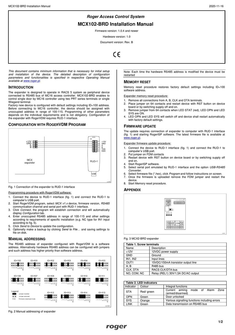
RKD32 cabinet is delivered as a complete set with internal connections and its installation requires only
connection of power supply and wall mounting inside premises.
Fig. 1 RKD32 overview
2. Characteristics
•Operates standalone or as a part of RACS 5 access control system
•Local management from a control panel
•Remote management from web browser
•Remote management from the RACS 5 access control system software (VISO application)
•Graphic control panel with a 7" touch screen
•Built-in Mifare® and EM 125 kHz cards reader
•Support for secure Mifare sectors
•Optional identification on external reader with Wiegand interface
•Optional identification on external reader with RS485 EPSO 3 (Roger) interface
•One-time PINs
•User photo upon key take/return
•32 keys in the RKD32 main depositor
•32 keys in the RKD32EXT extension depositor
•24 keys in the RKD24CT-EXT extension depositor
•Possibility to connect 5 RKD32EXT or RKD24CT-EXT expansion depositors to the RKD32 main
depositor
•Permanent connection of the key with the fob without the use of seals
•Possibility of using seals connecting the key with the fob

RKD32 v2 Installation and Configuration Manual.doc 20.07.2022
4/23
•Keys blocked mechanically in slots
•Contactless identification and key presence control via Mifare® proximity key fob
•Time dependant access rights to keys
•Limitation of the number of keys taken by the user
•Internal and external group of keys
•Two user option for keys
•Card + PIN authorization option
•Alert signalisation when key not returned within predefined time
•Email notifications upon alarm events
•Free access to all keys when operating in Office Mode
•Option to return keys without user identification (Quick Key Return Mode)
•Fixed or variable key position mode
•Light indication of slot with selected key
•Reservation of keys
•Key status comments
•User activities reports
•Key usage reports
•Generating and sending reports
•Voice prompts
•Emergency unlocking of all keys via an external signal (e.g. from the fire protection system)
•Emergency unlocking of the keys
•Door opening detection
•Enclosure opening detection
•Metal enclosure in RAL7016 colour
•RKD32 dimensions: 600 x 969 x 183 mm
•RKD32EXT dimensions: 600 x 677 x 183 mm
•SG option: P2 class anti-burglary glass
•SH option: Electric roller shutter instead of depository door
•MK option: Key to unlock the case in the Master Key system
•ND option: Cabinet without door
•SDK
•230VAC supply
•10 years of post-warranty service
•No obligatory warranty maintenance required
3. Power supply
Inside the control panel is a 230V power supply, connection module and a place for a buffer battery (7-18
Ah). To connect the power supply, unscrew the screw covered his housing and connect the 230VAC power
cables and the protective conductor.
Note: All connections must be made without power being supplied. It is forbidden to connect more than one
buffer battery.
In the event of power failure, fobs and keys can be released in an emergency after connecting a powerbank
(with a minimum 2A rated output) to a USB socket secured with a lockable flap, and then unlock the cabinet
door using the DOOR button and to unlock keys with the ROW1-4 buttons. In the case of many cabinets,
the procedure must be executed individually.
4. Cabinet
RKD32 cabinet is made of stainless metal sheet which is powder painted in RAL7016 (anthracite grey). As
standard, the RKD32 is equipped with a door with a tempered glass panel. Depending on the option, the
cabinet can be equipped with an P2 class anti-burglary glass panel, full door or without a door. There is also
a variant with an electrically raised and lowered shutter. Cabinet can be equipped with mechanical locks in
the Master Key system. The cabinet dimensions in standard version are given in fig. 5.
RKD32 v2 Installation and Configuration Manual.doc 20.07.2022
5/23
5. RFID fobs
The RKD32 includes 32 RFID fobs which are attached to keys or other supervised items. A key can be
attached to the fob manually without any specialized tools. When a key is placed on a ring and the ring is
inserted into a fob then it is not possible to detach the key from the fob without damaging it. This prevents
possible tampering with keys and fobs.
In order to join a key (or other object) with an identification fob, place the key on the metal ring, and then
press the ring so that only the oval part is visible. After joining, verify the correctness of the latch mechanism
by attempting to pull the key from the key fob. Optionally when secured element cannot be mounted on the
ring then it can be attached to hole in the fob using wire and seal.
Fig. 2 RFID fob
6. MD70 panel
Management of RKD32 is performed by means of MD70 panel with graphic touch screen, sounder, and
Mifare/EM 125kHz card reader. More information on the panel is given in its Operating Manual which is
available at www.roger.pl.
7. Identification
Following user identification methods are offered by the panel:
•MIFARE Ultralight/Classic/Plus/DESFire and EM125kHz proximity cards
•PINs
•RFID fobs
MIFARE cards
By default, the panel reads serial numbers (CSN) of MIFARE cards but it is possible to program cards with
own numbers (PCN) in selected and encrypted sectors of card memory. The use of PCN prevents card
cloning and consequently it significantly increases security in the system. More information on MIFARE
cards with PCN is given in section 7 and in AN024 application note which is available at www.roger.pl.
EM 125kHz cards
By default, the panel also reads the serial number of EM 125kHz cards. The EM 125kHz card reader works
in parallel with the reading of Mifare cards. In the MD70 device settings it is possible to limit card reading to
one of two standards.
PINs
The panel accepts variable length PINs (by default 4-16 digits). PIN entered with keypad must be concluded
with # or OK key.

RKD32 v2 Installation and Configuration Manual.doc 20.07.2022
6/23
RFID fobs
If the option Quick key return mode is enabled (table 2) then key fob can be used for identification at MD70
panel to open the door and return the key to unoccupied slot. The recommended orientation for fob reading
at the panel and fob reading at RUD-3 reader is shown below.
Fig. 3 RFID fob reading at MD70 panel
Fig. 4 RFID fob reading at RUD-3 reader
8. Other proximity cards and biometrics
User can be identified at MD70 panel with other methods if additional external reader is connected. Any
MCT series reader or RFT1000 fingerprint reader can be used for that. Such reader must be configured with
ID=915 address and connected to RS485 A and RS485 B screw terminals of MCX4D module. If it is
necessary to use other identification method which is not offered by Roger, then external reader with
Wiegand interface can be connected. In such scenario an additional MCX102 expander with ID=915
address must be installed inside the cabinet. Wiegand reader can be connected to IN1 (D0 line) and IN2
(D1 line) screw terminals of the expander while the expander is connected to RS485 A and RS485 B screw
terminals of the MCX4D module.
9. Connection with the alarm control panel
RKD32 is equipped with tamper detectors which enable detection of cabinet enclosure opening. Additionally
tamper detector is located inside MD70 panel. Opening of RKD32 or MD70 enclosure is signalled on LCK4
transistor output of MCX4D (cabinet 1) board (fig. 10). Door ajar warning is signalled when user becomes
logged out (manually or automatically) to the panel’s starting screen. The warning is generated acoustically
by MD70 panel for the time specified by the parameter Door open too long prealert time (table 2). If the door
remains opened when time elapses, then BELL4 output of MCX4D (cabinet 1) board is activated for 3
minutes or till door closing. BELL4 output is activated immediately also when door is opened by force. Both
LCK4 and BELL4 outputs can be connected to intruder alarm system, siren, or other alarm device.

RKD32 v2 Installation and Configuration Manual.doc 20.07.2022
7/23
10. Release all keys from external system
In case of fire alarm detection or any other emergency, the RKD32 can release all locks to enable key
collecting by any person without authorisation. Such release requires connection of fire alarm system output
to DR3 screw terminal of MCX4D (cabinet 1) board. As long as output line is activated, door lock and key
fob locks are released. In such scenario the option Fire alarm support (fobs released) (table 2) must also be
enabled.
11. Installation
Two people are required for installation of RKD32. Before installation, turn locks shown in fig. 5
simultaneously to detach both back covers. 230V power supply with a protective wire should be connected
to the control panel housing and connected to the power supply located under the cover secured with a
screw. The protective conductor must be connected to the connection block. Behind the electronic modules
there is a space for the one battery (up to 18Ah). The battery should be connected to the MCX4D module
using the cables included in the set.
Between each depository cabinet and the control panel enclosures, the following should be carried out:
• 12V power cables (min. 1mm2) by connecting them to the appropriate 12V, GND terminals of the
connection module,
• RJ45 cable (unshielded twisted pair cat.5) connecting to the appropriate BOX1-6 socket, the maximum
length of the cable is 5m,
• In the case of the first cabinet, run the USB cable from the control panel housing and connect it to the USB
cable in the key cabinet.
After making the connections, the enclosure should be attached to the base mounted on the wall as shown
in fig. 8, while closing the enclosure locks will self-latch. Communication with the key cabinet (in network
mode) and via a web browser can be realized via Ethernet (RJ45 socket on the MD70 board) or Wi-Fi
(control panel network settings are described in the MD70 manual). Connect green plug to the "MD70"
socket on the connection panel and optionally connect the Ethernet cable and mount the housing on the
base screwed to the wall.
Note: After changing the number of cabinets (e.g., adding RKD32EXT), start device scanning (after logging
in by a user with configuration rights to the Settings / Configuration / Detect devices) in order to properly
handle all slots. RKD32-EXT must first be connected with the RJ45 cable to the connection module in the
control panel housing, and then the power supply should be connected.

RKD32 v2 Installation and Configuration Manual.doc 20.07.2022
8/23
Fig. 5 Inside RKD32 with back cover removed
Fig. 6 Base of the control panel housing

RKD32 v2 Installation and Configuration Manual.doc 20.07.2022
9/23
Fig. 7 Back cover
Fig. 8 Wall mounting

RKD32 v2 Installation and Configuration Manual.doc 20.07.2022
10/23
Fig. 9 Connection of additional cabinets (RKD32EXT) to main cabinet (RKD32)
Fig. 10 Connection module in control panel housing
12. Support for optional function
In order to support additional functionalities, it is possible to connect executive elements (e.g., an alarm
siren) to the outputs of the MCX4D expander located in cabinet no. 1. Additionally, the DR3 input line is
dedicated to remote release of all keys (e.g., control from the fire protection system). The functions of the
accessory I / O zones of the MCX4D expander are described in the table below, while the electrical
parameters of the zones are available in the expander user's manual. In order to provide easy access to the
terminal blocks, remove the cover of expander cables, and then unscrew the device fixing plate in order to
slide the entire assembly out of the housing. After making the connections, install in reverse order.

RKD32 v2 Installation and Configuration Manual.doc 20.07.2022
11/23
Table 1. Screw terminals and sockets
Terminal/
socket
Description
+12V
12VDC power supply
GND
Ground
BELL4
15VDC/1A output line for door alarms
LCK4
15VDC/1A output line for tamper alarms
DR3
Input line to release all keys
MASTER
RJ45 socket for communication with connection module
USB socket designed to connect flash memory (for backup or reports saving) is available inside first cabinet,
after door opening in the right bottom corner (fig. 11).
Fig. 11 USB MASTER socket
13. RAACA app
After connection of power supply, the MD70 panel will start RAACA app. When started for the first time the
panel will offer to create default Master user with 9999 password. You must also select the operating mode
of the device:
•Any fob position: keys can be returned to any socket
•Fixed fob position: each key is assigned a socket to return it to
Additionally, for the SH cabinet variant, select the Depository equipped with a shutter option, and for the ND
cabinet variant select Depository without door. If items other than keys are stored in the cabinet, after
selecting the option Cabinet with general purpose assets , the text phrase "key" in the device interface will
be replaced with "asset".
Then app can be accessed with 9999# password (if created) or with 12345* administrator password. The
administrator account is intended for the installer or the person who manages the system i.e. for
maintenance and service purposes. Daily service and configuration of RKD32 should be done by means of
user account with the appropriate authorization.
Note: Both default passwords should be changed to your own passwords as described in section 17.

RKD32 v2 Installation and Configuration Manual.doc 20.07.2022
12/23
Fig. 12 Default starting screen
Fig. 13 Main menu
When in the top right corner is selected then Alarm Center is started. It shows all alarm events (forced
opening, tamper, etc.) registered by RKD32 in selected time range. The colour of icon corresponds to
following statuses:
•White: No unconfirmed alarms.
•Orange: Alarm(s) from the past is/are in the memory of device.
•Red: At least one unconfirmed alarm is still on.
When is selected then office mode will be started after returning to the starting screen. In office mode
door lock and (depend of configuration) key locks are released indefinitely but keys which are reserved with

RKD32 v2 Installation and Configuration Manual.doc 20.07.2022
13/23
blocking will not be released. Office mode can also be automatically started and finished by schedule which
can be defined in Settings window (fig. 15) and assigned with the command Office Mode schedule (table 3).
When is selected then Report Center is started as in fig. 14. After selection of Events tile it is possible to
browse, events (e.g., user login, key collecting, etc.) and after selection of in the same window it is
possible to delete and export events registered by RDK32. Key Report and User Report enable to display
respectively events related to particular key and events related to particular user. In both cases events can
be exported. The statistics allows you to check the times of keys in a given period of time. Events in Report
Centre can be exported to pendrive connected to MASTER USB port (fig. 11), exported to internal memory,
or sent by email according to settings in Configuration window (table 2). Available formats are XLS (Excel)
and PDF.
Fig. 14 Report Center
When is selected in top right corner of the main menu then statuses of keys in the system are
displayed. It informs whick keys are collected, by whom and which keys are reserved.
When is selected then settings window is displayed as in fig. 15.
Fig. 15 Settings window

RKD32 v2 Installation and Configuration Manual.doc 20.07.2022
14/23
Keys
When selected then the list of keys enrolled in the system is displayed. New key can be enrolled by
selection of Add command and then by reading fob at MD70 reader or inserting the fob into one of
unoccupied slots. Editing and deleting can be done by long clicking of an object on the list.
Assigning the key to the Inner zone allows the implementation of key anti-passback function. The user can
collect a key from another zone only when he returns all keys belonging to inner zone. The inner zone is
intended for keys that should stay as short as possible outside the cabinet (e.g. record office, confidential
office).
The option Required return time allows to control the return of a key on time. After exceeding the indicated
time, a related event is generated and can be displayed in the Alarm Center.
Commission get mode - after selecting this option, when trying to collect a key, authorization is required by
another user who has rights to the given key.
Card + PIN mode - to get the key, you must identify with both the card and the PIN. When trying to collect a
key, the application will ask you to read the card or enter the PIN, depending on the type of medium that
was initially used when logging in.
If both of the above options are selected, the card must be read, and the PIN code entered to confirm the
commission collection.
Group option allows you to easily identify the key’s position on the list of available assets. After selecting
specific group, the key will be marked with the appropriate colour on the list.
Schedules
When selected then list with predefined Always and Neverschedule is displayed. New schedule can be
defined by selection of Add command and then Add range. Editing and deleting can be done by long
clicking of an object on the list. Schedule consists of time periods which are specified for days of a week.
Schedules can be used to limit authorisations and to manage office mode.
Authorisations
When selected then list of authorisations is displayed. New authorisation is defined by selection of Add
command. Editing and deleting can be done by long clicking of an object on the list. Authorisation may
concern access to keys, settings, event log, key status and may enable key reservation override.
Authorisations are assigned to users in the next steps of configuration.
Cards, PINs
When selected then list of cards and PINs is displayed. Cards and PINs are used for identification of users
at MD70 panel. Adding, editing and deleting is possible on the list. During card enrolment its number can be
read at MD70 reader.
Users
When selected then list of users is displayed. Users can be assigned with cards, PINs and authorisations.
The Fob limit option allows you to specify the total number of keys that the user can collect at the same
time. Value 0 means no limit. Additionally, Quick key get mode and Master exemption can be enabled. The
first option enables to release authorised keys automatically when user is logged at MD70 panel so the
manual selection of key from the list is not necessary. For this mode the option Quick key get mode (table 2)
must be enabled. The Master exemption option assigns unlimited authorisations in the system for a user.
Configuration
When selected then list of parameters given in table 2 is displayed.
Table 2. Parameter list in Configuration window
General
Admin password
Administrator password. In case of login at MD70 panel the admin
password is concluded with * key. Range: 4-10 digits. Default value:
12345.
Logout when door closed
Parameter enables automatic user logout and reverting to starting
screen when door is closed. Range: ON, OFF. Default value: ON.
Automatic logout time [s]
Parameter defines time after which user is automatically logged out
and panel reverts to starting screen if no actions are performed by
user in the main menu of the panel. Range: 0-99. Default value: 60.

RKD32 v2 Installation and Configuration Manual.doc 20.07.2022
15/23
Automatic logout
Parameter enables automatic user logout and reverting to starting
screen when Automatic logout time elapses. Range: ON, OFF. Default
value: ON.
Alarm signalling time [min]
Parameter defines time for tamper alarm signalling on output LCK4.
Range: 0-99. Default value: 3.
Door open too long prealert time
[s]
Parameter defines time for acoustic warning at MD70 panel when door
is opened, and user is logged out. Range: 0-99. Default value: 60.
Fire alarm support (fobs release)
Parameter enables emergency release of door and key locks as long
as the input DR3 is triggered by external system e.g., fire alarm
system. Range: ON, OFF. Default value: OFF.
Office mode: cabinet door only
After selecting this option, while in office mode, the lock of the
depository door is released, and the keys remain locked. Default
value: OFF.
Selective cabinet’s opening
After selecting this option, only the cabinets where available keys are
located (after logging in for quick key get mode or after indicating the
key to be collect) and those cabinets from which the keys were
collected by the user will be opened.
Fast relogin
After activating the option, it is possible to change the logged in user
without logging out (only by reading the card).
Events with photos
After selecting this option, photos will be taken when users log in.
Keys
Quick key return mode
Parameter enables quick key returning after identification at the MD70
panel with key fob. In such scenario, user card or PIN are not required
to open cabinet door and return a key. This can be used for example
by temporary worker after finishing his job in a room. Range: ON, OFF.
Default value: ON.
Show absent key on list
Parameter enables to display collected keys both in key selection
window and keys status window. Range: ON, OFF. Default value: ON.
Fast get: show absent key info
Parameter enables to display message on keys which are currently not
available for quick collecting by user. The message is displayed when
user logs at the panel. Range: ON, OFF. Default value: OFF.
Function: identify key
After selecting this option, it is possible to identify the key. In order to
identify, read the key on the MD70 panel reader after logging in.
Shortcut to getting key
Automatic display of the list of keys after logging in. Note - active only
for the activated "Disable reservation" option and the mode of any key
position, and for the user who has no access to the application
settings. Default value: OFF.
Shortcut: logout after get single
key
The parameter activates automatic logout after getting one key and
reduces the idle time in the get key activity to 10s. Note - the
parameter works only for the " Shortcut to getting key" option. Default
value: OFF.
Email notification
Enabling the parameter starts sending e-mail notifications about alarm
events and when return time exceeded.
Comments
Reporting a comment about the
equipment status
After activating the option, a dialog box will be displayed during the key
retrieval and return, where it is possible to add a comment regarding
the key status or other request for the system administrator
Comments on demand
This option enables the possibility of entering a comment at any time.
Note: this option replaces the key reservations icon.

RKD32 v2 Installation and Configuration Manual.doc 20.07.2022
16/23
Predefinied comment content (1)
After you enter your text, it will appear as an option to check when
reporting a comment.
Predefinied comment content (2)
After you enter your text, it will appear as an option to check when
reporting a comment.
Predefinied comment content (3)
After you enter text, it will appear as an option while typing your
comment. The predefined content may be completed by the user, eg
after entering the text "Mileage [km]", the user may enter the car's
odometer reading when returning the key.
Note: when none of the 3 texts is defined, only the option to enter your
own comment will be available when entering a comment.
Reservation
Disable reservations
The parameter blocks the possibility of defining a key reservation.
Default value: OFF.
Block reserved key
Parameter enables key blocking by default when key is reserved.
Range: ON, OFF. Default value: OFF.
Maximum reservation time [h]
Parameter defines maximal period for reservation of key by user.
Range: 0 –99. Default value: 30.
Display
Custom wallpaper
Parameter enables switching between default and custom wallpaper
for MD70 panel. Custom wallpaper is indicated by Select wallpaper
command in menu. Range: ON, OFF. Default value: OFF.
Font color
Parameter specifies colour of the font used on MD70 starting screen.
Range: Light, Dark, Orange. Default value: Light.
Voice prompts
Enabling the option activates playback of the voice messages. Default
value: OFF.
RACS 5 settings
RACS 5 mode
Parameter enables RKD32 operation in network mode and
management by means of VISO software from RACS 5 system.
Server address
Parameter defines IP address of server with virtual controller.
Communication port
Parameter defines communication port of server with virtual controller.
Default value: 9788.
Login
Parameter defines login for communication with virtual controller.
Communication password
Parameter defines password for communication with virtual controller.
TLS
When checked, TLS encryption of communication is activated
MAC
Info box with MD70 MAC address.
Device name (comment)
Parameter specifies the name of RKD32 which is then used in reports
and logs.
WWW settings
Web access enable
Parameter enables RKD32 configuration and management via web
browser.
Port
Parameter defines communication port for web browser access. Due
to security reasons the port cannot be below 1024. Default value:
8888.
Login
Parameter defines login for web browser access.
Password
Parameter defines password for web browser access.

RKD32 v2 Installation and Configuration Manual.doc 20.07.2022
17/23
Email account
Address
Email account which is used for sending messages and reports from
RKD32.
Login
Email account login for email sending by RKD32.
Password
Email account password for email sending by RKD32.
SMTP port
Email port. Default value: 587.
Host
Email host address.
SSL
Parameter enables SSL encryption for email sending. Range: ON,
OFF. Default value: OFF.
Address 1
Recipient email address.
Address 2
Recipient additional email address.
Table 3. Commands in menu in Configuration window
Select wallpaper
Command enables indication of custom wallpaper (800x480px, *.jpg
format) for MD70 starting screen. Additionally, the parameter Custom
wallpaper (table 2) must be enabled.
Detect devices
Command starts the view of the list of devices in the RKD32 system.
After adding another depositor cabinet, run a scan to detect new
devices.
Office Mode schedule
Command enables assignment of schedule to office mode. The
schedule can be defined after selection of Schedules in Configuration
window.
Key slot settings
Command enables to adjust the light level of key slots.
Check for update
Command enables to check and download updates. In such case the
RKD32 must be connected to computer network.
Install update
Command enables installation of downloaded update.
Import users from PRMaster
Command enables to import users from PR Master software of
RACS 4 system as explained in section 17.
Configuration export
This command allows you to export configuration settings for transfer
to another depositor or for backup
Configuration import
The command restores the previously saved device configuration
Factory reset
Command enables to restore factory settings as explained in section
17.
Office mode
When selected then office mode is started in the same way as in case of previously described icon
which is located in the top right corner of main menu (fig. 13).
Events
When selected then Report Centre is started in the same way as in case of previously described icon
which is located in the top right corner of main menu (fig. 13).
Key report
When selected then history of particular key is displayed. Events can be deleted, exported to external
memory i.e. pendrive connected to MASTER socket at RKD board (fig. 11) or send by email according to
settings in Configuration window.

RKD32 v2 Installation and Configuration Manual.doc 20.07.2022
18/23
Manual
When selected then app manual is displayed on MD70 screen.
Menu in Settings window
Menu in window shown in fig. 15 includes additional commands that are not available in the menu
displayed in Configuration window.
Table 4. Commands in menu in Settings windows
Show launcher
Command enables to exit RKD32 app and start Android environment.
Default password is admin.
System settings
Command enables configuration of Android system settings. More
information is given in MD70 manual.
MD70 settings
Command enables configuration of MD70 parameters. More
information is given in MD70 manual.
Files
Command starts app that enables file navigation at MD70 panel.
About
Command displays change log.
License
Command displays license agreement for Roger software.
License file
Command displays information on uploaded RKD32 licenses in regard
of network mode and management via web browser.
Export database
Command enables to make backup of RKD32 settings on pendrive as
explained in section 17.
Import database
Command enables to import RKD32 settings from file on pendrive as
explained in section 17.
Remote support
Command enables to establish remote connection with MD70 panel in
computer network for the purpose of technical support by specialist as
explained in section 17.
14. Configuration in standalone mode
Keys
1. Attach keys to RFID fobs.
2. Log in at the panel (default PIN: 9999#), select and then Keys.
3. In the opened window select Add.
4. In the next window name the key (e.g., Room 101), click Value and read fob at MD70 reader (fig.
3) or insert fob into one of free slots.
5. You can set other key options as needed.
6. Enrol remaining fobs with keys into system.
Schedules (optional)
1. Log in at the panel (default PIN: 9999#), select and then Schedules.
2. In the opened window select Add.
3. In the next window name the schedule and click Add range.
4. Specify periods for days of week. Schedules can be applied for authorisations and office mode.
Authorisations
1. Log in at the panel (default PIN: 9999#), select and then Authorisations.
2. In the opened window select Add.
3. In the next window name the authorisation and click Location to indicate keys which can be collected by
user with this authorisation.
4. Optionally click Schedule and assign previously created schedule to limit the authorisation to specified
time periods.

RKD32 v2 Installation and Configuration Manual.doc 20.07.2022
19/23
5. Additionally, you can select if the authorisation gives access to settings, event log and keys status as
well as enables to override blocking of reserved keys.
Card, PINs
1. Log in at the panel (default PIN: 9999#), select and then Cards, PINs.
2. In the opened window select Add card or Add PIN in order to specify factor(s) that can be used to
identify user at MD70 panel. Similarly, as in case of fob, card number can be read at MD70 reader
after clicking Card code.
Users
1. Log in at the panel (default PIN: 9999#), select and then Users.
2. In the opened window select Add.
3. In the next window name the user (e.g., first and last name). Click Cards, PINs to assign previously
defined factors that can be used to identify user at MD70 panel. Click Authorisations to assign
previously created authorisations which will specify keys that can be collected by user in particular time
periods (schedules).
4. Additionally, and optionally, quick get key mode can be enabled so authorised keys could be released
automatically after user logging without need for selection of key(s) from the list and Master exemption
can be enabled to assign unlimited authorisations to a user. Master exemption is usually assigned to
system operator. Setting a value other than zero for the Fob limit allows you to limit the number of keys
a user can retrieve.
Note: Editing and deleting requires long clicking of an object (e.g., user) on the list.
User importing from PR Master (RACS 4)
Users who were defined in PR Master software of RACS 4 system can be imported to avoid another manual
enrolment of the same data on the level of RKD32 key cabinet.
1. Start PR Master program, select Users and then Export in order to export users with their card numbers
and PINs to PRM.CSV file.
2. If it is necessary to preserve non-latin characters, then open PRM.CSV file in Windows notepad and
save with UTF-8 coding.
3. Copy PRM.CSV file on pendrive.
4. Connect the pendrive to MASTER USB port (fig. 11).
5. Log in at the panel (default PIN: 9999#), select and then Configuration
6. In the opened window select and then Import users from PR Master.

Reservation
Key can be reserved by selection of area in the main menu (fig. 13) and then Add command. In the next
window a time range must be specified and the option Block key during reservation can be selected. If the
global option Block reserved key option is enabled (table 2) then all keys are blocked by default during
reservation. Key which is reserved without blocking can be collected during reservation by any user who is
authorised for the key and then such collecting is only accompanied by warning on ongoing reservation.
User who is assigned with authorisation which has the option Key reservation override authorisation can
collect reserved keys without limits including keys which were reserved with blocking.
15. Configuration via web browser
RKD32 key cabinet can be remotely configured and managed via web browser. In such scenario it is
necessary to define parameters in section WWW settings (table 2). The communication with MD70 panel
can be in Ethernet network or Wi-fi network. The IP address of the panel in LAN/WAN is configured by
means of Ethernet app after exiting RAACA app with the command Show launcher (table 4). Prior to
establishing connection with the RKD32 it is necessary to enter IP address and communication port (8888
by default). The port may require unblocking in firewall and/or antivirus software.
Note: Configuration via web browser requires license purchase. You can verify if your RKD32 has the
proper license selecting License file command (table 4).

RKD32 v2 Installation and Configuration Manual.doc 20.07.2022
20/23
Fig. 16 RKD32 web app
16. Configuration in network mode
RKD32 key cabinet can be remotely operated in network mode. In such scenario, the configuration and
management of keys and users is performed on the level of VISO software from RACS 5 system and
RKD32 users can use the same factors (e.g., Mifare cards, PINs) as in access control system.
Prior to connection with RACS 5 system the key cabinet must be configured in regard of parameters given
in section RACS 5 settings (table 2). Further configuration and management of key cabinet is explained in
AN042 application note which is available at www.roger.pl
Note: Configuration via web browser requires license purchase. You can verify if your RKD32 has the
proper license selecting License file command (table 4).
17. Management and general issues
Admin password change
1. Log in at the panel (default PIN: 9999# or 12345*), select and then Configuration.
2. Click Admin password and replace default 12345 password with your own.
Default Master user password change (if available)
1. Log in at the panel (default PIN: 9999# or 12345*), select and then Cards, PINs.
2. Select Add PIN in order to define new factor and return to Settings window.
3. Select Users.
4. Long click USER_ADMIN and then select Edit.
5. Click Cards, PINs deselect default PIN_ADMIN (e.g., 9999) and select your previously defined PIN.
Programmable cards
By default, the panel reads serial numbers (CSN) of MIFARE cards but it is possible to program cards with
own numbers (PCN) in selected and encrypted sectors of card memory. The use of PCN prevents card
cloning and consequently it significantly increases security in the system. In order to configure how the
panel will read card numbers:
1. Log in at the panel (default PIN: 9999#) and select .
Other manuals for RKD32
2
Table of contents
Other Roger IP Access Controllers manuals

Roger
Roger LRT-1 User manual

Roger
Roger PR402DR User manual

Roger
Roger RKD32 User manual

Roger
Roger MCT12M User manual

Roger
Roger CEB12 User manual

Roger
Roger MCT86M-IO-HR-CH User manual

Roger
Roger MCT80M-BLE User manual

Roger
Roger MCT88M-IO User manual

Roger
Roger MCT68ME-IO User manual

Roger
Roger PR622 User manual

Roger
Roger PR402DR User manual

Roger
Roger PR402DR-BRD User manual

Roger
Roger PR302 User guide

Roger
Roger MC16-PAC-EX/ST-2-KIT User manual

Roger
Roger MC16-PAC-1-KIT User manual

Roger
Roger PR402 User guide

Roger
Roger MCX402-BRD User manual

Roger
Roger MCT12M User manual

Roger
Roger MCT12E User manual

Roger
Roger PR102DR User manual