Page 3of 19
1. INTRODUCTION
1.1 This manual
This manual contains minimum information that is necessary to properly install the devices and to
perform initial tests. Full functional description of the controllers has been included in the document
– PRxx1 series controllers, Functional description and programming guide. Whereas PR Master
software, which is used for access control system management is described in detail within the
manual for that software.
If PR411DR and PR411DR-BRD controllers are not clearly distinguished in particular paragraph,
then information specified for PR411DR are also valid for PR411DR-BRD. But if PR411DR-BRD name
is used in particular paragraph then the information concerns only that specific type of controller.
1.2 Typing conventions
Examples
italics letters
Specific names related to RACS 4
system with first capital letter
Notes separated with two lines (upper, lower) from the standard text
2. DESCRIPTION AND SPECIFICATION
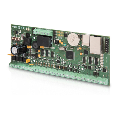
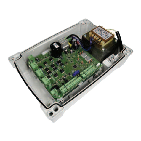
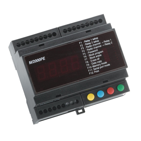
Both controllers, PR411DR and PR411DR-BRD are identical in regard of their functions, but differ
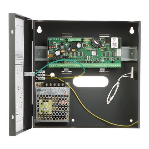
mechanically. PR411DR is installed inside plastic enclosure fitted to mounting on DIN 35 mm rail,
while PR411DR-BRD is just a PCB module without enclosure.
The new, factory-made controller has the address ID=00 and is equipped with the MASTER card
which can be used both for manual programming and for initial tests after installation of the
controller and connection of external reader with keypad. In case of PR411DR, the section of 35mm
DIN rail is included and it can be used to fix controller in the box, which is not equipped with DIN
35mm rail. PR411DR-BRD controller also includes attachments for installation on DIN 35mm rail.
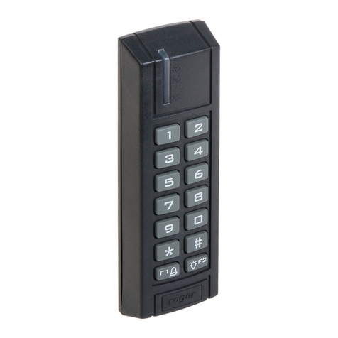
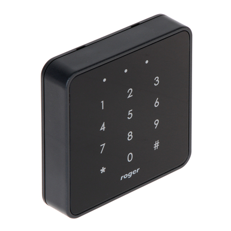
PR411DR is not equipped with built-in reader and it requires connection of external reader
operating in RACS Clock&Data standard (PRT series terminals) or Wiegand 26…66bit standard.
The controller can be programmed manually by means of commands entered with keypad or by
means of PC with PR Master software. Manual commands are described in the document – PRxx1
series controllers, Functional description and programming.
Connection of PR411DR type controller to PC requires installation of communication interface e.g.
UT-2USB, UT-4DR, UT-4, RUD-1 or installation of CPR32-NET network controller.
Table 1. Specification
Supply voltage Nominal 18VAC, min./max. range 17-22VAC
Nominal 12VDC, min./max. range 10-15VDC
Nominal 24VDC, min./max. range 22-26VDC
Backup battery 13.8V/7Ah, charging current app. 300mA
Current
consumption Average 100 mA (excluding load points connected to AUX and/or TML
outputs)
Inputs Eight (IN1...IN8) NO/NC inputs, electrically biased to +12V via 5.6kΩ
resistor, triggering level app. 3.5V
Relay outputs Two relay outputs (REL1 and REL2) with single NO/NC contact, 30V/1.5A
(REL1) and 230VAC/5A (REL2)
Transistor outputs Two outputs (IO1 and IO2) open collector type, 15VDC/1A max. load
Power supply Two power supply outputs: 12VDC/0.2A (TML) and 12VDC/1A (AUX)
