Roger MCT86M-IO-HR-CH User manual

Roger Access Control System
MCT86M-IO-HR-CH Operating Manual
Product version: 1.0
Firmware version: 1.1.18 or newer
Document version: Rev. B

MCT86M-IO-CH-HR Operating Manual 09.07.2020
2/15
1. DESIGN AND APPLICATION
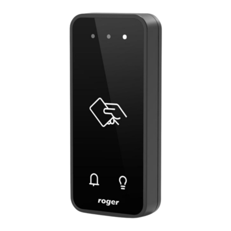
The MCT86M-IO-CH-HR is an access terminal with card holder dedicated to RACS 5 system. The device
enables identification of users by 13,56 MHz MIFARE® Ultralight/Classic/Plus/DESFire proximity cards and
it is generally dedicated to hotel applications. The main function of the terminal is to disable electric supply
of the room when guest is absent and to control such hotel signalisations as Luggage Service, Make Up
Room, Cafeteria and Do Not Disturb by means of touch function keys. The device is connected to access
controller through RS485 interface.
Note: The application of RACS 5 system in hotels is explained in AN033 application note which is available
at www.roger.pl.
Characteristics
RACS 5 system access terminal with card holder
13.56 MHz MIFARE Ultralight/Classic/Plus/DESFire proximity cards
LED indicator
Buzzer
4 function keys with LED indicators
3 parametric (EOL) inputs
2 transistor outputs
1 relay output
RS485 interface
Tamper protection
Screw terminals
Power supply
The terminal requires power supply voltage in range of 11-15VDC. It can be supplied from MCX2D/MCX4D
expander of MC16-PAC-KIT, from MC16 access controller (e.g. TML output) or from dedicated power
supply unit. The supply wire diameter must be selected in such way that the voltage drop between supply
output and the device would be lower than 1V. The proper wire diameter is especially critical when device is
located in long distance from the supply source. In such a case the use of dedicated power supply unit
located close to the device should be considered. When separate power supply unit is used then its minus
should be connected to controller’s GND by means of signal wire with any diameter. It is recommended to
use UTP cable for connection of device to controller. The table below shows maximal UTP cable lengths in
relation to the number of wires used for power supply.
Table 1. Power supply cabling
Number of UTP wire pairs for power supply
Maximal length of power supply cable
1
150m
2
300m
3
450m
4
600m

MCT86M-IO-CH-HR Operating Manual 09.07.2020
3/15
Fig. 1 MCT supply from MC16 access controller
Fig. 2 MCT supply from dedicated power supply unit
RS485 bus
The communication with MC16 access controller is provided with RS485 bus which can encompass up to
16 devices of RACS 5 system, each with unique address in range of 100-115. The bus topology can be
freely arranged as star, tree or any combination of them except for loop. The matching resistors
(terminators) connected at the ends of transmitting lines are not required. In most cases communication
works with any cable type (standard telephone cable, shielded or unshielded twisted pair etc.) but the
recommended cable is unshielded twisted pair (U/UTP cat.5). Shielded cables should be limited to
installations subject to strong electromagnetic interferences. The RS485 communication standard used in
the RACS 5 system guarantees proper communication in a distance of up to 1200 meters as well as high
resistance to interferences.
Note: Do not use more than single pair in UTP cable for RS485 communication bus.

MCT86M-IO-CH-HR Operating Manual 09.07.2020
4/15
Function keys
The terminal is equipped with four touch function keys. They are mainly dedicated to control such hotel
signalisations as Luggage Service, Make Up Room, Cafeteria, Do Not Disturb but they can be alternatively
assigned with other functions within high level configuration (VISO). Within low level configuration
(RogerVDM) of the terminal it is possible configure if terminal distinguishes short and long key pressings.
Consequently each type of key press can be assigned with different function.
LED indicators
The terminal is equipped with bicolour (red/green) LED indicator which is used to signal presence of
authorised card in card holder and it can be additionally programmed with other available functions within
high level configuration (VISO). The indicator includes two sets of LEDs which are represented in VISO
management software as two individual outputs: LED CARD ABSENT (red) and LED CARD PRESENT
(green).
The terminal is also equipped with four red LED indicators at four function keys. These four LED indicators
can be used to confirm key pressing and they are programmed within high level configuration (VISO) on the
level of Access Point in the same way as other RACS 5 outputs.
Fig. 3 Indicators LED line
Note: Synchronic pulsing of LED indicator signifies lost communication with MC16 controller.
Buzzer
The terminal is equipped with buzzer which is used to signal integral functions and it can be additionally
programmed with other available functions within high level configuration (VISO).
Inputs
The terminal offers 3 general purpose parametric inputs of NO, NC, 3EOL/DW/NO and 3EOL/DW/NC type
and 1 input internally connected to tamper contact. Input types and electric parameters such as response
time and parametric resistors are defined within low level configuration (RogerVDM). Input functions are
assigned within high level configuration (VISO). Multiple functions can be assigned to the same input at the

same time.

MCT86M-IO-CH-HR Operating Manual 09.07.2020
5/15
Table 1. Input types
NO input
NC input
NO input can be in normal or in triggered state. In
normal state CAcontacts are opened. Input
triggering is caused by CAcontacts closing.
NC input can be in normal or in triggered state. In
normal state CAcontacts are closed. Input triggering
is caused by CAcontacts opening.
3EOL/DW/NO input
3EOL/DW/NC input
3EOL/DW/NO input is operated in such way that CA
contacts closing is interpreted as triggering of the
first input while CBclosing is interpreted as
triggering of the second input. In VISO software DW
input type is represented by two independent inputs.
Each can be used for different purpose and
assigned with different function.
3EOL/DW/NC input is operated in such way that CA
contacts opening is interpreted as triggering of the
first input while CBopening is interpreted as
triggering of the second input. In VISO software DW
input type is represented by two independent inputs.
Each can be used for different purpose and
assigned with different function.
Parametric resistors
The same values of parametric resistors are used for all inputs i.e. 1kΩ; 1,2kΩ; 1,5kΩ; 1,8kΩ; 2,2kΩ; 2,7kΩ;
3,3kΩ; 3,9kΩ; 4,7kΩ; 5,6kΩ; 6,8kΩ; 8,2kΩ; 10kΩ; 12kΩ. In case of 3EOL/DW (Double Wiring) input type,
Alarm A resistor defines a value of resistor used to detect triggering of the first input while Alarm B resistor
defines a value of resistor used to detect triggering of the second input. Alarm A resistor value must differ
from value of Alarm B resistor at least by three positions in the list above. Total resistance of wire used to
connect contacts to input should not exceed 100 Ω. Default values of parametric resistors:

MCT86M-IO-CH-HR Operating Manual 09.07.2020
6/15
Alarm A = 2,2 kΩ
Alarm B = 5,6 kΩ
Response time
Response time parameter defines minimal impulse time on the input which triggers the input. Each input can
be configured individually in range of 50 to 5000 ms within low level configuration (RogerVDM).
Tamper detector
Built-in tamper (sabotage) detector enables detection of unauthorized opening of device’s enclosure as well
as detachment of the enclosure from wall. The detector is internally connected to the terminal’s input. It
does not require low level configuration (RogerVDM) or any additional installation arrangements but it is
essential to mount front panel in such way as the tamper detector (fig. 5) would firmly press the back panel.
The detector requires high level configuration which consists in assignment of the function [133] Tamper
Toggle on the level of a Main Board of a controller in VISO software navigation tree.
Outputs
The terminal offers 2 transistor open collector type outputs (15V/150mA rated) and 1 relay output with
NO/NC contacts (30V/1.5A DC/AC rated). Electric parameters such as polarity are configured within low
level configuration (RogerVDM). Function are assigned to outputs within high level configuration (VISO).
Multiple functions with different priorities can be assigned to the same output at the same time.
Identification
By default the terminal reads serial numbers (CSN) of MIFARE cards but it is possible to program cards with
own numbers (PCN) in selected and encrypted sectors of card memory. The use of PCN prevents card
cloning and consequently it significantly increases security in the system. More information on MIFARE card
programming is given in AN024 application note which is available at www.roger.pl.
The technical characteristics of the device are guaranteed for RFID cards supplied by Roger. Cards from
other sources may be used, but they are not covered by the manufactures warranty. Before deciding to use
specific Roger products with third-party contactless cards, it is recommended to conduct tests that will
confirm satisfactory operation with the specific Roger device and software in which it operates.
2. INSTALLATION
Table 3. Screw terminals
Name
Description
IO2
OUT2 output line
IO1
OUT1 output line
IN3
IN3 input line
IN2
IN2 input line
IN1
IN1 input line
NO
REL1 relay normally opened contact
NC
REL1 relay normally closed contact
COM
REL1 relay common contact
B
RS485 bus, line B
A
RS485 bus, line A
GND
Ground
+12V
12VDC power supply

MCT86M-IO-CH-HR Operating Manual 09.07.2020
7/15
Fig. 4 MCT86-IO-CH-HR installation

MCT86M-IO-CH-HR Operating Manual 09.07.2020
8/15
Fig. 5 Programming jumpers
Installation guidelines
The terminal should be mounted on a vertical structure (wall) away from sources of heat and
moisture.
Front panel should be attached in such way as the tamper detector (fig. 5) would firmly press the
back panel.
All electrical connections should be done with disconnected power supply.
If the terminal and controller are not supplied from the same PSU then GND terminals of both
devices must be connected with any wire.
Clean front panel regularly by means of wet cloth and mild detergent. Do not clean by means of
abrasive materials and strong cleaners like alcohols, solvents, etc. Damages to screen surface are
beyond the scope of warranty.
3. OPERATION SCENARIO
The terminal when connected to MC16 access controller can be used for hotel automation including room
power supply control based on card presence in the holder. The example of connection diagram for such
scenario is shown in fig. 6 where the power supply is controlled by MC16 output and additional external
230VAC relay. Such relay can also be connected to other available output also on the MCT82M-IO-CH
terminal or MCX series expander connected to the controller

MCT86M-IO-CH-HR Operating Manual 09.07.2020
9/15
Fig. 6 Typical connection diagram for the terminal and MC16 access controller
4. CONFIGURATION
Low level configuration (RogerVDM)
The purpose of low level configuration is to prepare device for operation in RACS 5 system.
Programming procedure with RogerVDM software:
1. Connect the device to RUD-1 interface (fig. 7) and connect the RUD-1 to computer’s USB port.
2. Place jumper on MEM contacts (fig. 5).
3. Restart the device (switch power supply off and on or short RST contacts for a moment) and LED
indicator will pulsate.
4. Start RogerVDM program, select MCT device, firmware version, RS485 communication channel and
serial port with RUD-1 interface.
5. Click Connect, the program will establish connection and will automatically display Configuration tab.
6. Enter unoccupied RS485 address in range of 100-115 and other settings according to requirements of
specific installation.
7. Click Send to Device to update the configuration of device.
8. Optionally make a backup by clicking Send to File… and saving settings to file on disk.
9. Remove jumper from MEM contacts and disconnect the device from RUD-1 interface.
Note: Do not read any cards when the device is configured with RogerVDM.

MCT86M-IO-CH-HR Operating Manual 09.07.2020
10/15
Fig. 7 Connection of MCT terminal to RUD-1 interface (low level configuration)
Table 4. List of low level parameters
Communication settings
RS485 address
Parameter defines device address on RS485 bus. Range: 100-115.
Default value: 100.
RS485 communication timeout [s]
Parameter defines delay after which device will signal lost
communication with controller by means of its LED indicators. When
set to 0 then signaling is disabled. Range: 0-64s. Default value: 20s.
RS485 encryption
Parameter enables encryption at RS485 bus. Range: [0]: No, [1]: Yes.
Default value: [0]: No.
RS485 encryption key
Parameter defines key for encryption of communication at RS485 bus.
Range: 4-16 ASCII characters.
Optical signalisation
Backlight level [%]
Parameter defines backlight level. When set to 0 then backlight is
disabled. Range: 0-100. Default value: 100.
Backlight switching off when no
activity
Parameter enables backlight switching off after 20 s from the latest
card reading or key pressing. The backlight is restored again when
card or key is used. Range: [0]: No, [1]: Yes. Default value: [1]: Yes.
Acoustic signalisation
Buzzer loudness level [%]
Parameter defines buzzer loudness level. When set to 0 then buzzer is
disabled Range: 0-100. Default value: 100.
Short sound after card read
Parameter enables short sound (beep) generating by buzzer when
card is read. Range: [0]: No, [1]: Yes. Default value: [1]: Yes.
Keypad settings
Keypad activated
Parameter enables deactivation of keypad. Range: [0]: No, [1]: Yes.
Default value: [1]: Yes.
[F1], [F2], [F3, [F4] key press
options
Parameter defines key press type for [F1], [F2], [F3], [F4] function key.
Range: [1]: Short press only, [2]: Long press only, [3]: Short and long

MCT86M-IO-CH-HR Operating Manual 09.07.2020
11/15
press. Default value: [1]: Short press only.
Advanced settings
Stop card/PIN reading when
buffer full
Parameter enables to reject card/PIN reading by device till previous
card/PIN is transmitted to controller. Range: [0]: No, [1]: Yes. Default
value: [0]: No.
Card/PIN buffer timeout [s]
Parameter defines time for card/PIN storing in device buffer. When the
time elapses the buffer is cleared even if card/PIN is not transmitted to
controller. Range: 0-64. Default value: 10.
AF type
Parameter defines authentication factor type returned by terminal.
Default value: [16]: Number 40 bits.
Input types
IN1, IN2, IN3
Parameter defines input type. Range: [1]: NO, [2]: NC, [3]: EOL/NO,
[4]: EOL/NC, [5]: 2EOL/NO, [6]: 2EOL/NC, [7]: 3EOL/NO, [8]:
3EOL/NC, [9]: 3EOL/DW/NO, [10]: 3EOL/DW/NC. Default value: [1]:
NO.
Input response times
IN1, IN2, IN3 [ms]
Parameter defines minimal duration of pulse which is required to
trigger the input. Range: 50-5000. Default value: 50.
Parametric (EOL) input resistances
Tamper, Alarm A, Alarm B [Ohm]
Parameter defines resistor for parametric (EOL) inputs.
Output polarity
OUT1, OUT2, REL1
Parameter defines polarity of output. Normal polarity means that the
output by default is switched off while Reversed polarity means that
the output by default is switched on. Range: [0]: Normal polarity, [1]:
Reversed polarity. Default value: [0]: Normal polarity.
Comments
DEV, CDI, IN1, IN2, IN3, IN4
(Tamper), OUT1, OUT2, REL1,
Parameter defines any text or comment which corresponds to the
object. It is later displayed in VISO program.
Serial card number (CSN) settings
Serial number length (CSNL) [B]
Parameter defines the number of bytes from serial card number (CSN)
which will be used to generate returned card number (RCN). RCN is
the actual card number read by reader and it is created as sum of
serial card number (CSN) and programmable card number (PCN).
Programmable card number (PCN) settings for Mifare Classic
Sector type
Parameter defines sector type with programmable number (PCN). If
the option [0]:None is selected then card returned number (RCN) will
include only CSN and PCN will be discarded. Range: [0]: None, [1]:
SSN, [2]: MAD. Default value: [0]: None.
Format
Parameter defines format of PCN. Range: [0]: BIN, [1]: ASCII HEX.
Default value: [0]: BIN.
First byte position (FBP)
Parameter defines the position of the first byte for PCN in data block
on card. Range: 0-15. Default value: 0.
Last byte position (LBP)
Parameter defines the position of the last byte for PCN in data block
on card. Range: 0-15. Default value: 7.
Sector ID
Parameter defines sector number where PCN is stored. Range: 0-39.
Default value: 1.
Application ID (AID)
Parameter defines application ID number (AID) which indicates sector

MCT86M-IO-CH-HR Operating Manual 09.07.2020
12/15
where PCN number is stored. Range: 0-9999. Default value: 5156.
Block ID
Parameter defines block number where PCN is stored. Range: 0-2 to
for sectors 0-31 and 0-14 for sectors 32-39. Default value: 0.
Key type
Parameter defines key type used to access sector with PCN. Range:
[0]: A, [1]: B, [2]: Roger. Default value: [0]: A.
Key
Parameter defines 6 bytes (12 HEX digits) key for accessing sector
where PCN is stored.
Programmable card number (PCN) settings for Mifare Plus
Sector type
Parameter defines sector type with programmable number (PCN). If
the option [0]:None is selected then card returned number (RCN) will
include only CSN and PCN will be discarded. Range: [0]: None, [1]:
SSN, [2]: MAD. Default value: [0]: None.
Format
Parameter defines format of PCN. Range: [0]: BIN, [1]: ASCII HEX.
Default value: [0]: BIN.
First byte position (FBP)
Parameter defines the position of the first byte for PCN in data block
on card. Range: 0-15. Default value: 0.
Last byte position (LBP)
Parameter defines the position of the last byte for PCN in data block
on card. Range: 0-15. Default value: 7.
Sector ID
Parameter defines sector number where PCN is stored. Range: 0-39.
Default value: 1.
Application ID (AID)
Parameter defines application ID number (AID) which indicates sector
where PCN number is stored. Range: 0-9999. Default value: 5156.
Block ID
Parameter defines block number where PCN is stored. Range: 0-2 to
for sectors 0-31 and 0-14 for sectors 32-39. Default value: 0.
Key type
Parameter defines key type used to access sector with PCN. Range:
[0]: A, [1]: B. Default value: [0]: A.
Programmable card number (PCN) settings for Mifare Desfire
Sector type
Parameter defines sector type with programmable number (PCN). If
the option [0]:None is selected then card returned number (RCN) will
include only CSN and PCN will be discarded. Range: [0]: None, [1]:
Desfire file. Default value: [0]: None.
Format
Parameter defines format of PCN. Range: [0]: BIN, [1]: ASCII HEX.
Default value: [0]: BIN.
First byte position (FBP)
Parameter defines the position of the first byte for PCN in data block
on card. Range: 0-15. Default value: 0.
Last byte position (LBP)
Parameter defines the position of the last byte for PCN in data block
on card. Range: 0-15. Default value: 7.
Application ID (AID)
Parameter defines application ID number (AID) which indicates sector
where PCN number is stored. Range: 0-9999. Default value: F51560.
File ID (FID)
Parameter defines file identifier in AID. Range: 0-32 for Desfire EV1
and 0-16 for Desfire EV0. Default value: 0.
Communication protection level
Parameter defines encryption method for communication between
card and reader. Range: [0]: Plain, [1]: Data authentication by MAC,
[2]: Full encryption. Default value: [0]: Plain.
Key number
Parameter defines application key number used for file read. Range:
0-13. Default value: 0.
Key type
Parameter defines encryption key type for Desfire file. Range: [0]:
TDES Native, [1]: TDES Standard, [2]: 3-KTDES, [3]: AES128. Default

MCT86M-IO-CH-HR Operating Manual 09.07.2020
13/15
value: [0]: TDES Native.
Key
Parameter defines access key for Desfire file with PCN. 3-KTDES key
is 24 bytes (48 HEX digits), TDES and AES keys are 16 bytes (32
HEX digits).
Manual addressing procedure
Manual addressing procedure enables configuration of new RS485 address with all other settings
unchanged.
1. Remove all connections from A and B lines.
2. Place jumper on MEM contacts (fig. 5).
3. Restart the device (switch power supply off and on or short RST contacts for a moment) and LED
indicator will pulsate.
4. Enter 3 digits of RS485 address in range of 100-115 with any MIFARE card.
5. Wait till device confirms addressing with continuous sound.
6. Remove jumper from MEM contacts and restart the device.
Terminals without keypad can be addressed with multiple card readings where the N number of readings
emulates digit of the address. Three series of readings with any MIFARE proximity card are necessary to set
the address. After each series wait for two beeps and proceed with the next digit. Zero digit is emulated with
10 readings.
Example:
Programming of ID=101 address with card readings:
1. Read card 1 time and wait for two beeps.
2. Read card 10 times and wait for two beeps.
3. Read card 1 time and wait for two beeps.
Memory reset procedure
Memory reset procedure resets all settings to factory default ones including ID=100 address.
1. Remove all connections from A and B lines.
2. Place jumper on MEM contacts (fig. 5).
3. Restart the device (switch power supply off and on or short RST contacts for a moment) and LED
indicator will pulsate.
4. Read any MIFARE card 11 times.
5. Wait till device confirms reset with continuous sound.
6. Remove jumper from MEM contacts and restart the device.
High level configuration (VISO)
The purpose of high level configuration is to define logical functioning of the terminal which communicates
with the MC16 access controller and it depends on applied scenario of operation. The example of access
control system configuration is given in AN006 application note while hotel system configuration is explained
in AN033 application note. Both notes are available at www.roger.pl.
5. FIRMWARE UPDATE
The update requires connection of device to computer with RUD-1 interface (fig. 8) and starting RogerVDM
software. The latest firmware file is available at www.roger.pl.
Firmware update procedure:
1. Connect the device to RUD-1 interface (fig. 8) and connect the RUD-1 to computer’s USB port.
2. Place jumper on FDM contacts (fig. 5).
3. Restart the device (switch power supply off and on or short RST contacts for a moment).
4. Start RogerVDM program and in the top menu select Tools and then Update firmware.
5. In the opened window select device type, serial port with RUD-1 interface and path to firmware file
(*.hex).
6. Click Update to start firmware upload with progress bar in the bottom.

MCT86M-IO-CH-HR Operating Manual 09.07.2020
14/15
7. When the update is finished, remove FDM jumper and restart the device.
Fig. 8 Connection of MCT terminal to RUD-1 interface (firmware update)
6. SPECIFICATION
Table 5. Specification
Supply voltage
Nominal 12VDC, min./max. range 10-15VDC
Current consumption
(average)
~60 mA
Inputs
Three parametric inputs (IN1..IN3) internally connected to the power supply
plus through a 5.6kΩ resistor. Approx. 3.5V triggering level for NO and NC
inputs.
Relay output
Relay output (REL1) with single NO/NC contact, 30V/1.5A DC/AC max. load
Transistor outputs
Two (IO1, IO2) open collector outputs, 15VDC/150mA max. load
Tamper protection
Enclosure opening reported to access controller
Proximity cards
13.56MHz MIFARE Ultralight, Classic, DESFire EV1 and Plus
Distance
1200m maximal cable length for RS485 bus between controller and terminal
IP Code
IP41
Environmental class
(according to EN
50133-1)
Class II, indoor general conditions, temperature: -10°C to +50°C, relative
humidity: 10 to 95% (no condensation)
Dimensions H x W x D
155 x 85 x 22 mm
Weight
~180g
Certificates
CE
7. ORDERING INFORMATION
Table 6. Ordering information
MCT86M-IO-CH-HR
MIFARE DESFire/Plus access terminal with card holder; on-board I/Os; hotel

MCT86M-IO-CH-HR Operating Manual 09.07.2020
15/15
signalling function key panel.
RUD-1
Portable USB-RS485 communication interface dedicated to ROGER access
control devices.
8. PRODUCT HISTORY
Table 7. Product history
Version
Date
Description
MCT86M-IO-CH-HR v1.0
06/2018
The first commercial version of product
This symbol placed on a product or packaging indicates that the product
should not be disposed of with other wastes as this may have a negative
impact on the environment and health. The user is obliged to deliver
equipment to the designated collection points of electric and electronic
waste. For detailed information on recycling, contact your local authorities,
waste disposal company or point of purchase. Separate collection and
recycling of this type of waste contributes to the protection of the natural
resources and is safe to health and the environment. Weight of the
equipment is specified in the document.
Contact:
Roger sp. z o.o. sp.k.
82-400 Sztum
Gościszewo 59
Tel.: +48 55 272 0132
Fax: +48 55 272 0133
Tech. support: +48 55 267 0126
E-mail: biuro@roger.pl
Web: www.roger.pl
Table of contents
Other Roger IP Access Controllers manuals

Roger
Roger MCT68ME-IO-I User manual

Roger
Roger QUADRUS SERIES User manual

Roger
Roger PR102DR User manual

Roger
Roger MCX402-BRD User manual

Roger
Roger LRT-1 User manual

Roger
Roger MC16 User manual

Roger
Roger PR402DR User manual

Roger
Roger MCT12M User manual

Roger
Roger PR411DR User manual

Roger
Roger MCT88M-IO User manual

Roger
Roger MCT88M-IO User manual

Roger
Roger MCX4D User manual

Roger
Roger F7 User manual

Roger
Roger MCT82M SERIES User manual

Roger
Roger PR411DR-SET User manual

Roger
Roger MCX2D User manual

Roger
Roger PR602LCD-DT-I User manual

Roger
Roger MCT68ME-IO User manual

Roger
Roger MCT12M User manual

Roger
Roger PR402DR User manual