manuals.online logo
Brands
  1. Home
  2. •
  3. Brands
  4. •
  5. Roger
  6. •
  7. IP Access Controllers
  8. •
  9. Roger MCT88M-IO User manual

Roger MCT88M-IO User manual

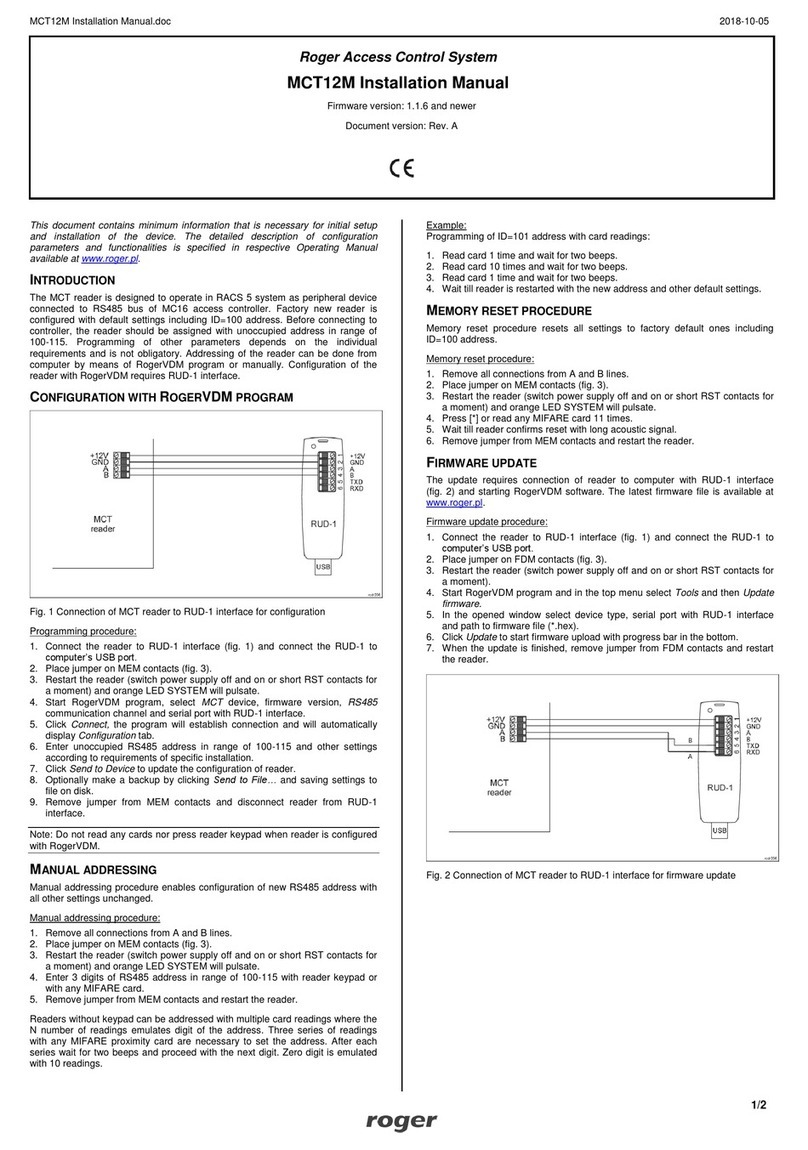
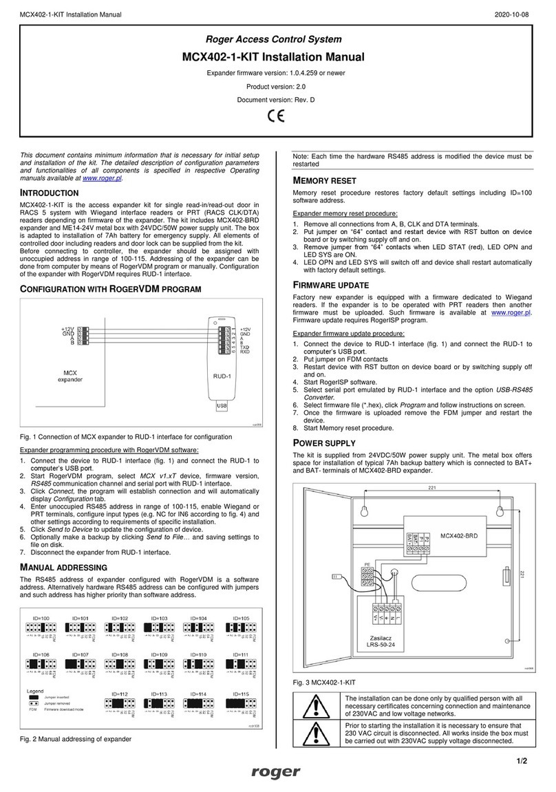
MCT88M-IO Installation Manual 2021-12-08
1/2
Roger Access Control System
MCT88M-IO Installation Manual
Firmware version: 2.0.8.197 and newer
Document version: Rev. J
This document contains minimum information that is necessary for initial setup
and installation of the device. The detailed description of configuration
parameters and functionalities is specified in respective Operating manual
available at www.roger.pl.
INTRODUCTION
The terminal is designed for operation with MC16 access controller (RACS 5
system). Alternatively the device can communicate with virtual controller via
Ethernet (LAN) and operate as PoS terminal or assets tracking terminal. Factory
new terminal is configured with default settings including ID=100 address.
DEVICE CONFIGURATION
The terminal can be configured in regard of various parameters (including
address) in order to adapt it to the requirements of specific installation. Device
can be configured from VISO v2 management software or RogerVDM utility
software.
Note: Remote configuration of device from VISO v2 software is possible only if
jumper is placed on MEM contacts (fig. 3). If the jumper is removed then such
configuration is blocked. In case of factory new device, jumper is placed on MEM
contacts.
CONFIGURATION WITH VISO V2PROGRAM
In RACS 5 v2 system, when connected to MC16 controller, the terminal can be
installed at site without previous configuration. According to AN006 application
note, its address and other settings can be configured from VISO v2
management software and during such configuration the access to its service
contacts (fig. 3) is not required.
CONFIGURATION WITH ROGERVDM PROGRAM
Fig. 1 Connection of MCT reader to RUD-1 interface (configuration)
Programming procedure:
1. Connect the device to RUD-1 interface (fig. 1) and connect the RUD-1 to
computer’s USB port.
2. Remove jumper from MEM contacts (fig. 3) if it is placed there.
3. Restart the device (switch power supply off and on) and orange LED
SYSTEM will pulsate. Then within 5 seconds place jumper on MEM contacts
and the terminal will display CONFIG MODE text.
4. Start RogerVDM program, select MCT device, v1.0 firmware version, RS485
communication channel and serial port with RUD-1 interface.
5. Click Connect, the program will establish connection and will automatically
display Configuration tab.
6. Select RS485 communication interface and specify unoccupied RS485
address in range of 100-115 or select Ethernet communication interface and
specify IP address. Configure other low level configuration parameters as
needed.
7. Click Send to Device to update the configuration of device.
8. Optionally make a backup by clicking Send to File… and saving settings to
file on disk.
9. Remove jumper from MEM contacts and disconnect device from RUD-1
interface.
Note: If the USB port does not offer enough power output then supply the
terminal from external PSU with min. 12VDC/200mA power output.
Note: Do not read any cards nor press keypad when device is configured with
RogerVDM.
MANUAL ADDRESSING
Manual addressing procedure enables configuration of new RS485 address with
all other settings unchanged.
Manual addressing procedure:
1. Remove all connections from A and B lines.
2. Remove jumper from MEM contacts (fig. 3) if it is placed there.
3. Restart the device (switch power supply off and on) and orange LED
SYSTEM will pulsate. Then within 5 seconds place jumper on MEM contacts
and the terminal will display CONFIG MODE text.
4. Enter 3 digits of RS485 address in range of 100-115 with keypad.
5. Wait till device starts to emit continuous sound.
6. Leave jumper on MEM contacts to enable further configuration of device from
VISO v2 software or remove jumper from MEM contacts to block such remote
configuration.
7. Restart the device.
MEMORY RESET
Memory reset procedure resets all settings to factory default ones including
ID=100 address.
Memory reset procedure:
1. Remove all connections from A and B lines.
2. Remove jumper from MEM contacts (fig. 3) if it is placed there.
3. Restart the device (switch power supply off and on) and orange LED
SYSTEM will pulsate. Then within 5 seconds place jumper on MEM contacts
and the terminal will display CONFIG MODE text.
4. Press [*] or read any MIFARE card 11 times.
5. Wait till device confirms reset with continuous sound.
6. Leave jumper on MEM contacts to enable further configuration of device from
VISO v2 software or remove jumper from MEM contacts to block such remote
configuration.
7. Restart the device.
FIRMWARE UPDATE
The firmware of device can be changed to newer or older version. Firmware can
be uploaded to the terminal by means of included memory card. The latest
firmware file is available at www.roger.pl.
Note: During the firmware update process, it is necessary to ensure continuous
and stable power supply for the device. If interrupted the device may require
repair by Roger.
Note: Backup configuration with RogerVDM software before firmware update
because the update will restore factory default settings.
Firmware update procedure:
1. Disconnect power supply.
2. Press and remove memory card from socket (fig. 3).
3. Using memory card reader, copy main firmware (*.frg) to the card and
rename it as FW.BUF.
4. Insert the card into socket.
5. Connect power supply. During firmware update the LED STATUS (red) will
pulsate and the LED OPEN (green) will be switched on and after firmware
update the LED SYSTEM (orange) will pulsate.
6. Restart the device (switch power supply off and on) and orange LED
SYSTEM will pulsate. Then within 5 seconds place jumper on MEM contacts
and the terminal will display CONFIG MODE text.
7. Start RogerVDM program and perform low level configuration or restore the
configuration from backup file using Read from File… command.
MCT88M-IO Installation Manual 2021-12-08
2/2
APPENDIX
Fig. 2 Enclosure disassembly

Fig. 3 Service contact and memory card
Table 1. Screw terminals
Screw terminal
Description
+12V
12VDC power supply
GND
Ground
A
RS485 bus, line A
B
RS485 bus, line B
COM
REL relay common terminal
NC
REL relay output (NC)
NO
REL relay output (NO)
IN1
IN1 input line
IN2
IN2 input line
IN3
IN3 input line
OUT1
OUT1 output line
OUT2
OUT2 output line
1,2,3,4,5,6,7,8
Ethernet port
Table 2. Specification
Supply voltage
Nominal 12VDC, min./max. range 10-15VDC
Current consumption
(average)
~110 mA
Inputs
Three parametric inputs internally connected to
the power supply plus (+12V) through a 5.6kΩ
resistor, approx. 3.5V triggering level when
configured as NO or NC.
Relay output
Relay output with single NO/NC contacts, rated
30V/1A
Transistor outputs
Two (IO1,IO2) open collector outputs,
15VDC/150mA rated
Tamper protection
Enclosure opening reported to access controller
Identification methods
ISO/IEC14443A MIFARE Ultralight, Classic,
Desfire EV1 and Plus proximity cards
Mobile device (Android, iOS) compatible with NFC
Mobile device (Android, iOS) compatible with BLE
(Bluetooth Low Energy) v4.1
Reading range
Up to 7 cm for MIFARE and NFC
Up to 10 m for BLE –depends on ambient
conditions and particular mobile device. Terminal’s
radio power can be increased within low level
configuration.
Distances
Up to 1200 m between controller and terminal
(RS485)
IP Code
IP41
Environmental class
(acc. to EN 50133-1)
Class I, indoor general conditions, temperature:
+5°C to +40°C, relative humidity: 10 to 95% (no
condensation)
Dimensions H x W x D
85 x 155,5 x 21,5 mm
Weight
190g
Certificates
CE
Fig. 5 Connection of terminals and expanders to MC16 access controller
Fig. 6 Connection of door lock, door contact and exit button to MCTxx-IO
terminal
This symbol placed on a product or packaging indicates that the
product should not be disposed of with other wastes as this may
have a negative impact on the environment and health. The user is
obliged to deliver equipment to the designated collection points of
electric and electronic waste. For detailed information on recycling,
contact your local authorities, waste disposal company or point of
purchase. Separate collection and recycling of this type of waste
contributes to the protection of the natural resources and is safe to
health and the environment. Weight of the equipment is specified in
the document.
Contact:
Roger Sp. z o. o. sp. k.
82-400 Sztum
Gościszewo 59
Tel.: +48 55 272 0132
Fax: +48 55 272 0133
Tech. support: +48 55 267 0126
E-mail: support@roger.pl
Web: www.roger.pl

Other manuals for MCT88M-IO

4

Other Roger IP Access Controllers manuals

Roger MCT88M-IO User manual

Roger

Roger MCT88M-IO User manual

Roger RKD32 User manual

Roger

Roger RKD32 User manual

Roger MC16-PAC-3-KIT User manual

Roger

Roger MC16-PAC-3-KIT User manual

Roger OSR88M-IO User manual

Roger

Roger OSR88M-IO User manual

Roger PR411DR-SET User manual

Roger

Roger PR411DR-SET User manual

Roger RKD32 User manual

Roger

Roger RKD32 User manual

Roger MCT88M-IO User manual

Roger

Roger MCT88M-IO User manual

Roger MC16-PAC-1-KIT User manual

Roger

Roger MC16-PAC-1-KIT User manual

Roger MCX102-BRD User manual

Roger

Roger MCX102-BRD User manual

Roger MC16-PAC-16 User manual

Roger

Roger MC16-PAC-16 User manual

Roger MCX402-BRD User manual

Roger

Roger MCX402-BRD User manual

Roger EDGE1 Series Product manual

Roger

Roger EDGE1 Series Product manual

Roger MCT84M-BK-QB User manual

Roger

Roger MCT84M-BK-QB User manual

Roger MCT82M SERIES User manual

Roger

Roger MCT82M SERIES User manual

Roger PR411DR User manual

Roger

Roger PR411DR User manual

Roger MC16-PAC-1-KIT User manual

Roger

Roger MC16-PAC-1-KIT User manual

Roger PR411DR-SET User manual

Roger

Roger PR411DR-SET User manual

Roger LRT-1 User manual

Roger

Roger LRT-1 User manual

Roger PR612 User manual

Roger

Roger PR612 User manual

Roger PR622 User manual

Roger

Roger PR622 User manual

Roger PRT12MF-DES User manual

Roger

Roger PRT12MF-DES User manual

Roger RFT1000 Use and care manual

Roger

Roger RFT1000 Use and care manual

Roger MCX2 User manual

Roger

Roger MCX2 User manual

Roger ME-14-24V User manual

Roger

Roger ME-14-24V User manual

Popular IP Access Controllers manuals by other brands

FEITIAN AllinPass FIDO2 K33 user manual

FEITIAN

FEITIAN AllinPass FIDO2 K33 user manual

Alula RE6100P Series instructions

Alula

Alula RE6100P Series instructions

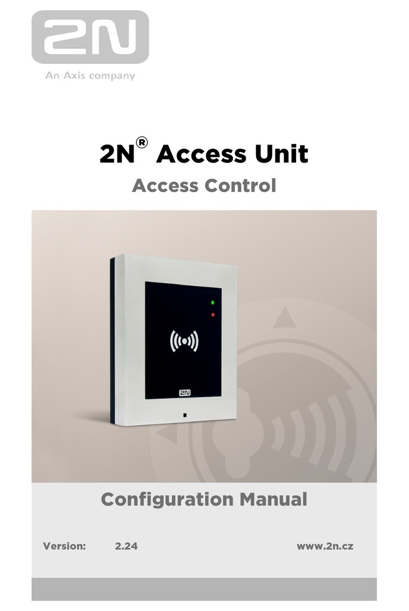
2N Access Unit Configuration manual

2N

2N Access Unit Configuration manual

Risco RP432DOR Installation and programming guide

Risco

Risco RP432DOR Installation and programming guide

Detex ES500 Series instructions

Detex

Detex ES500 Series instructions

PRASTEL EASYKW manual

PRASTEL

PRASTEL EASYKW manual

Chamberlain CAPAC manual

Chamberlain

Chamberlain CAPAC manual

Security Brands Ascent 16-X2 quick start guide

Security Brands

Security Brands Ascent 16-X2 quick start guide

Dahua ASR1102A user manual

Dahua

Dahua ASR1102A user manual

ZKTeco F19 installation guide

ZKTeco

ZKTeco F19 installation guide

Wasp B2000 user manual

Wasp

Wasp B2000 user manual

Genie GDG360BT user manual

Genie

Genie GDG360BT user manual

Gantner GAT Access 6600 Series quick start guide

Gantner

Gantner GAT Access 6600 Series quick start guide

Viking C-1000 Technical practice

Viking

Viking C-1000 Technical practice

eKey TOCAhome integra operating instructions

eKey

eKey TOCAhome integra operating instructions

Bosch PR115B Installer's reference guide

Bosch

Bosch PR115B Installer's reference guide

Idemia MorphoWave Compact Quick user guide

Idemia

Idemia MorphoWave Compact Quick user guide

NAPCO GEM-ACM1D installation instructions

NAPCO

NAPCO GEM-ACM1D installation instructions

manuals.online logo
manuals.online logoBrands
  • About & Mission
  • Contact us
  • Privacy Policy
  • Terms and Conditions

Copyright 2025 Manuals.Online. All Rights Reserved.