Roger PR302 User manual

PR302 Installation Guide
2020-10-19
2/10
Introduction
This document contents minimum information required for electrical installation of PR302 access
controller.
Installation
The PR302 can be installed in indoor location only. All electrical connections must be made before
power supply will be applied. Factory new unit is configured for address ID=00 and has programmed
MASTER PIN (1234) and MASTER card (delivered with the new device). The MASTER card/PIN can
be used for initial testing of the controller - the single use of MASTER card/PIN activates
momentarily REL1 output (for approx. 4s); double, consecutive use of MASTER card/PIN changes
controller’s arming mode and switches IO1 output to reverse state.
All devices working in one access system and connected to the same RS485 communication bus
should have common minus (common GND). This can be achieved by connecting all supply minuses
using additional (separate) wire or connecting each supply minus with earth, however the second
method might create problems when electrical potentials of the earth are not the same in different
parts of the electric installation.
Note: It is forbidden to short positive outputs (DC+) from various sources of power and/or other DC
outputs available in the system.
Setting address
Before controller will be connected to communications bus it should be configured to individual
address (ID number=00..99). The controller’s address can be set manually using Memory Reset
procedure or from PC computer. In order to set/change controller’s address from PC connect it to
any free COM port and then using PR Master program enrol it to database. Once the unit is found by
PR Master use relevant command to change its address and then disconnect it from PC and connect
to designated access installation.
Note: Connecting two or more controllers with the same address will cause communications conflict
on the communication bus.
Power supply
Controller requires 10-15VDC supply and consumes 100mA average current. The power source
should provide DC voltage free of interferences. Using poor quality switched mode power sources
can cause reduction of card reading distance. Always carefully calculate wire gauge used to supply
access controller, note that amount of current required by controller can rise momentary up to
200mA. The GND input to controller is also reference ground for RS485 com. bus and for all signal
lines used in controller.
Door Lock
In most cases door locks are inductive type loads and generate strong voltage surges when
switching to off state. This phenomenal can corrupt electronic circuits and change its behaviour. In
order to protect access controller from these effects, every inductive load (like door lock or any
other coil) should be protected with silicon diode (e.g. 1N4007) connected as close as possible to the
switched device. Also, door locks should be wired using separate pair of wires connected directly to
the source of power.
PR302 Installation Guide
2020-10-19
3/10
Inputs
The PR302 offers three programmable inputs (IN1, IN2 and IN3). All of them have the same
electrical structure and can be configured as NO or NC line. Each input is internally biased to supply
plus (+12V) through 15kΩ resistor what makes that supply plus is observed on the free (not
connected) input. The NO type input goes active when shorted to supply minus (GND). The NC line
in normal state should be connected to GND, it became triggered when connection with GND is
discontinued.
Relay output
The PR302 has one programmable relay output (REL1) which offers single NO/NC/COM contact
24V/1.5A rated. In normal state NC contact is shorted to COM wile NO remains isolated. When
active, NO is shorted to COM while NC remains isolated. When controller is not supplied or supplied
with voltage below its minimum level, relay output remains not active.
Transistor outputs
There are two transistor outputs (IO1 and IO2) available on the PR302 controller, both have
identical electrical structure. When not active (normal state) transistor outputs represent high
impedance, when active (triggered state) outputs short to supply minus (GND). Each output can
switch max. 1A DC while voltage connected to it must not exceed 15VDC. The IO1 and IO2 have
internal over-current protection which switches them off for currents above 1A.
RS485 Communication bus
The communications bus consist of three lines: A, B and cable’s shield (SHLD). Electrically, it
represents RS485 standard however neither the daisy chain structure nor terminating resistors are
required. Instead of this free topology of communication bus is allowed, the A/B wires can be laid
down using “three’’, “star” or any combination of them. It is recommended to use UTP cable for A
and B lines however other types of signal cables are accepted as well. The use of shielded cables
should be limited to these installation were strong electromagnetic interferences are expected.
The max. cable distances:
between communication interface and any controller on the bus: 1200m
between communication interface and CPR network controller (if installed): 1200m
between any access controller and CPR network controller (if installed): 1200m
When longer cable lengths are required then UT-4 interface can be used. Using UT-4 serial-to-
ethernet converter the distance is limited to area covered with computer network.

PR302 Installation Guide
2020-10-19
4/10
Connecting readers and expanders
Access terminals (readers) and expanders (e.g. XM-2-BRD, XM-8-BRD) can be connected to
controller through CLK and DTA lines. Controller can operate either with Roger access terminals
(using RACS data output format) or with any other type of readers which are equipped with Wiegand
or Magstripe interfaces. Any type of signal cable can be used for CLK and DTA lines. Each device
connected to controller through CLK/DTA line must have its individual address (0..15) however this
rule is valid for devices using RACS format but not for Wiegand or Magstripe interfaces.
Note: Normally, the maximum guaranteed cable length between controller and any other device
connected to CLK/DTA line is limited to 150m nevertheless when using RACS interface
communication will run satisfactory for up to 500m distances, however it is not guaranteed in every
case.
For best card reading results controller should be installed on non metal surface. When installed on
metal structure the reading range can be reduced up to 50%. This effect can be reduced by placing
non metal spacer (min. 10mm thick) between controller and metal surface where controller is
installed. Readers should be installed on at least 0.5m distance from each other, also two readers
should not be aligned along the same geometrical axes.
Connecting Wiegand and Magstripe readers
Follow schematic drawing below when connecting Wiegand or Magstripe readers to controller. Note,
that to prepare the controller for operation with those type of readers you must make adequate
settings in PR Master program.

PR302 Installation Guide
2020-10-19
5/10
Memory Reset
Memory Reset procedure enables erasing of current settings and returning to default factory
settings. Full procedure also allows to program new MASTER card/PIN as well as new address of the
controller. After Memory Reset procedure, the controller automatically enters normal working mode.

Simplified Memory Reset procedure (firmware 2.18.6 or newer)
Simplified Memory Reset restores default settings and automatically sets controller address ID=00.
MASTER card and PIN cannot be configured.
Remove connections to CLK and DTA terminals of the controller
Connect CLK terminal with DTA terminal
Press and hold MEMORY RESET button until LED OPEN (green) pulsates
Release MEMORY RESET button
Disconnect CLK and DTA terminals
After a few seconds the controller shall restart automatically and switch to normal mode
Simplified Memory Reset procedure (firmware older than 2.18.6)
Simplified Memory Reset restores default settings and enables programming of new MASTER card
while controller address is automatically configured as ID=00.
Press and hold MEMORY RESET button until LED OPEN (green) pulsates
Release MEMORY RESET button
Read any card at the controller —this will be a new MASTER card
After a few seconds the controller shall restart automatically and switch to normal mode
Full Memory Reset procedure
Full Memory Reset restores default settings and enables programming of new MASTER card, MASTER
PIN and controller ID address.
Press and hold MEMORY RESET button until LED OPEN (green) pulsates
Release MEMORY RESET button
Enter new MASTER PIN (3-6 digits) followed with the [#] key or skip this step and press only
the [#] key
Read any card at the reader —this will be a new MASTER card or skip this step and press
only the [#] key
Enter two digits (in range of 00 to 99) by means of keypad –this will be new ID address or
skip this step and press only the [#] key so the default ID=00 could be assigned
After a few seconds the controller shall restart automatically and switch to normal mode

PR302 Installation Guide
2020-10-19
6/10
After Memory Reset, controller resumes its work with default factory settings and entered address.
You can then initially test its operation using the MASTER card or PIN (if available). Using the
MASTER card/PIN once activates the REL1 output for 4 seconds (LED OPEN is on for the time
when REL1 is active). Using of MASTER card/PIN twice switches the IO1 output to the opposite state
and changes arming mode (LED STATUS changes its colour).
Note: If current address of the controller is hardware type (FixedID) then address entered within
Memory Reset procedure is ignored.
Firmware upgrade
During manufacturing process controller is programmed with latest version of firmware,
nevertheless it can be later upgraded with newer versions. Roger design team continuously work on
enhancements so the new firmware versions are released quite often (every new firmware version is
published on www.roger.pl). Our customers are advised to register at web site so Roger will let
inform when new versions are ready for download. The new firmware can be downloaded without
removal of the controller from live installation. The detailed description of firmware upgrade
procedure can be found in Firmware upgrade.pdf on www.roger.pl.
The new firmware is programmed into the controller by means of communication bus and doesn’t
require de-installation of the unit from its original location. For firmware upgrade the RogerISP
program is required. Once the controller is upgraded it should be fully reconfigured, also it is
necessary to update the RACS database which must be aligned with current version of controller’s
firmware (command …Networks/Controllers/Commands/Restart controller and verify
version..).
Note: Whenever new firmware is uploaded into the unit the PR Master program should be also
upgraded to latest available version.
Screw terminals
Name
Function
+12V
Power supply plus
0V (GND)
Power supply minus, also reference ground for inputs, RS485 and
CLK/DTA lines
IN1
IN1 input, internally pulled to supply plus through 15kΩ resistor
IN2
IN2 input, internally pulled to supply plus through 15kΩ resistor
IN3
IN3 input, internally pulled to supply plus through 15kΩ resistor
SHLD
RS485 cable’s shield
RS485 A
RS485 communication bus, line A
RS485 B
RS485 communication bus, line B
CLK
RACS Clock & Data interface, line CLOCK
DTA
RACS Clock & Data interface, line DATA
TAMPER
Tamper switch, line A, 24V/50mA rated
TAMPER
Tamper switch, line B, 24V/50mA rated
IO2
IO2 transistor output 15VDC/1.0A
IO1
IO1 transistor output 15VDC/1.0A
REL1-NC
REL1 output, normally closed contact, 24V/1.5A rated
REL1-COM
REL1 output, common contact, 24V/1.5A rated
REL1-NO
REL1 output, normally open contact, 24V/1.5A rated

PR302 Installation Guide
2020-10-19
7/10
Technical specification
Supply voltage
Nominal 12VDC, min./max. range 10-15VDC
Current consumption
average 80 mA
Anti-sabotage
Isolated contact, NC type, 24V/50mA rated, IP67
Reading distance
UP to 12 cm for ISO card (depends on card type)
Cards
EM 125 KHz (EM4100/4102 compatible)
Environmental class
(according to
EN50131-1)
Class I, Indoor, temperature: +5°C- +40°C, relative humidity: 10 to
95% (non-condensing)
Ingress protection
IP 30
Dimensions
105 X 105 X 31 mm
Weight
~ 140g
Certificates
CE
Note: Device can be cleaned by means of wet cloth and mild detergent without abrasive
components. In particular do not clean with alcohols, solvents, petrol, disinfectants, acids, rust
removers, etc. Damages resulting from improper maintenance and usage are not covered by
manufacturer warranty.
Ordering information
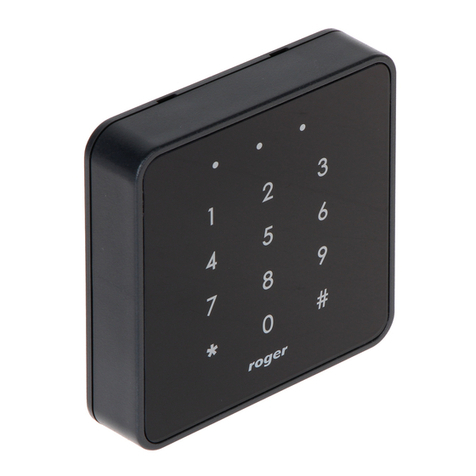
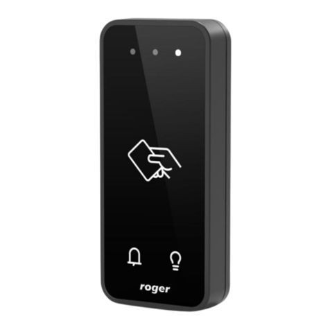
PR302
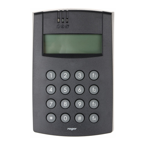
Indoor access controller with built-in EM 125 kHz proximity reader and keypad
XM-2
Input/output addressable extension module with plastic enclosure, digital
communication according to RACS Clock and Data protocol, two NO/NC inputs
and two relay outputs, each relay offers one NO/NC contact 24V/1.5A rated,
relay contacts protected by over-voltage components, two LEDs to indicate
triggering of relevant relay
XM-2DR
I/O expander; two NO/NC input lines and two relay outputs; DIN rail plastic
enclosure
UT-2
RS232-RS485 communication interface
UT-2USB
USB-RS485 communication interface
UT-4DR
Ethernet-RS485/RS232 communication interface

PR302 Installation Guide
2020-10-19
8/10

PR302 Installation Guide
2020-10-19
9/10

PR302 Installation Guide
2020-10-19
10/10
This symbol placed on a product or packaging indicates that the
product should not be disposed of with other wastes as this may
have a negative impact on the environment and health. The user
is obliged to deliver equipment to the designated collection points
of electric and electronic waste. For detailed information on
recycling, contact your local authorities, waste disposal company
or point of purchase. Separate collection and recycling of this type
of waste contributes to the protection of the natural resources
and is safe to health and the environment. Weight of the
equipment is specified in the document.
Contact:
Roger sp. z o.o. sp.k.
82-400 Sztum
Gościszewo 59
Tel.: +48 55 272 0132
Fax: +48 55 272 0133
Tech. support: +48 55 267 0126
E-mail: support@roger.pl
Web: www.roger.pl
Other manuals for PR302
2
Table of contents
Other Roger IP Access Controllers manuals

Roger
Roger MC16-PAC-1-KIT User manual

Roger
Roger MCT86M-IO-HR-CH User manual

Roger
Roger PR201 Assembly instructions

Roger
Roger MCT12M User manual

Roger
Roger PR402DR User manual

Roger
Roger PR411DR User manual

Roger
Roger RKD32 User manual

Roger
Roger MCX4D User manual

Roger
Roger PR301 Assembly instructions

Roger
Roger MCT12E User manual

Roger
Roger MC16-PAC-3-KIT User manual

Roger
Roger PR402DR User manual

Roger
Roger EDGE1 Series Product manual

Roger
Roger PR402DR-BRD User manual

Roger
Roger MCT12M User manual

Roger
Roger MCT88M-IO User manual

Roger
Roger RFT1000 User manual

Roger
Roger MC16-PAC-3-KIT User manual

Roger
Roger QUADRUS SERIES User manual

Roger
Roger MCX102-BRD User manual