manuals.online logo
Brands
  1. Home
  2. •
  3. Brands
  4. •
  5. Ruijie
  6. •
  7. Switch
  8. •
  9. Ruijie RG-S6100 Series Installation and operating manual
Ruijie RG-S6100 Series Installation and operating manual
Ruijie RG-S6100 Series Switches
Hardware Installation and Reference Guide
Document Version: V1.4
Date: 2023.07.11
Copyright © 2023 Ruijie Networks
Copyright
Copyright © 2023 Ruijie Networks
All rights are reserved in this document and this statement.
Any reproduction, excerption, backup, modification, transmission, translation or commercial use of this
document or any portion of this document, in any form or by any means, without the prior written consent of
Ruijie Networks is prohibited.
Trademark and are owned by Ruijie Networks.
All other trademarks or registered trademarks mentioned in this document are owned by their respective
owners.
Disclaimer
The products, services, or features you purchase are subject to commercial contracts and terms. Some or all of
the products, services or features described in this document may not be within the scope of your purchase or
use. Unless otherwise agreed in the contract, Ruijie Networks does not make any express or implied statement
or guarantee for the content of this document.
Due to product version upgrades or other reasons, the content of this document will be updated from time to
time. Ruijie Networks reserves the right to modify the content of the document without any notice or prompt.
This manual is for reference only. Ruijie Networks endeavors to ensure content accuracy and will not shoulder
any responsibility for losses and damages caused due to content omissions, inaccuracies or errors.
Ruijie RG-S6100 Series Multi-GE Switches Hardware Installation and Reference Guide (V1.4)
Technical support hotline: 4008-111-000
http://webchat.ruijie.com.cn
Preface
Intended Audience
This document is intended for:
Network engineers
Technical support and servicing engineers
Network administrators
Technical Support
Ruijie Networks website: https://www.ruijienetworks.com/
Technical support website: https://ruijienetworks.com/support
Case portal: https://caseportal.ruijienetworks.com
Community: https://community.ruijienetworks.com
Technical support email: [email protected]
Skype: [email protected]
Conventions
1. Conversions
Convention
Description
Bold font
Commands, command options, and keywords are in bold font.
Italic font
Arguments for which you supply values are in italic font.
[ ]
Elements in square brackets are optional.
{ x | y | z }
Alternative keywords are grouped in braces and separated by vertical
bars.
[ x | y | z ]
Optional alternative keywords are grouped in brackets and separated
by vertical bars.
&<1-n>
The argument before the sign (&) can be input for consecutive 1- n
times.
//
Double slashes at the beginning of a line of code indicate a comment
line.
2. Signs
The signs used in this document are described as follows:
Ruijie RG-S6100 Series Multi-GE Switches Hardware Installation and Reference Guide (V1.4)
Technical support hotline: 4008-111-000
http://webchat.ruijie.com.cn
Warning
An alert that calls attention to important rules and information that if not understood or followed can result in
data loss or equipment damage.
Caution
An alert that calls attention to essential information that if not understood or followed can result in function
failure or performance degradation.
Note
An alert that contains additional or supplementary information that if not understood or followed will not lead to
serious consequences.
Specification
An alert that contains a description of product or version support.
3. Note
The manual offers configuration information (including model, port type and command line interface) for
indicative purpose only. In case of any discrepancy or inconsistency between the manual and the actual version,
the actual version prevails.
Ruijie RG-S6100 Series Multi-GE Switches Hardware Installation and Reference Guide (V1.4)
- 4 -
1 Product Overview
RG-S6100 series multi-GE switches are the next-generation high-performance, high-security and multi-service
layer 3 Ethernet switches developed by Ruijie Networks. As aggregation switches in a campus network, this
series supports line-rate multi-layer switching, and is equipped with complete QoS policies for service-based
traffic prioritization, guaranteeing the transmission of critical traffic at almost zero latency. RG-S6100 series
multi-GE switches are 10GE switches. RG-S6110-24MG4VS-UP provides 24 multi-GE ports
(100ME/1GE/2.5GE/5GE), with each port supporting IEEE 802.3bt Type 4 (90 W) PoE, and four 25GE ports.
RG-S6110-48MG4VS2QXS-UP provides 48 multi-GE ports (100ME/1GE/2.5GE/5GE), with the first 24 ports
supporting IEEE 802.3bt Type 4 (90 W) PoE, and the last 24 ports supporting IEEE 802.3at Type 2 (30 W) PoE.
It also provides four 25GE ports and two 40GE ports. RG-S6120-12XMG4VS-UP-H provides 12 multi-GE ports
(100ME/1GE/2.5GE/5GE/10GE), with each port supporting IEEE 802.3bt Type 4 (90 W) PoE. It also provides
four 25G optical ports. RG-S6120-24XMG4XS4VS-UP-H provides 24 multi-GE ports
(100ME/1GE/2.5GE/5GE/10GE), with each port supporting IEEE 802.3bt Type 4 (90W) PoE. It also provides
four 10GE ports and four 25GE ports. RG-S6120-48XMG4VS2QXS-UP-H provides 48 multi-GE ports
(100ME/1GE/2.5GE/5GE), with the first 24 ports supporting IEEE 802.3bt Type 4 (90 W) PoE, and the last 24
ports supporting IEEE 802.3at Type 2 (30 W) PoE. It also provides four 25GE ports and two 40GE ports.
Specifications of RG-S6110 series switches:
Model
100GE
QSFP28
Ethernet
Ports
40GE
QSFP+
Ethernet
Ports
25GE
SFP28
Ethernet
Ports
10GE
SFP+
Ethernet
Ports
100ME/1G
E/2.5GE/5
GE
Multi-GE
Ethernet
Ports
Redund
ant
Fan
Modules
Redund
ant
Power
Modules
RG-S6110-24MG
4VS-UP
N/A
N/A
4
N/A
24
Fixed
fan
modules
Fixed
power
modules
RG-S6110-48MG
4VS2QXS-UP
N/A
2s
4
N/A
48
2+1
1+1
RG-S6120-12XM
G4VS-UP-H
N/A
N/A
4
N/A
12
Fixed
fan
modules
Fixed
power
modules
RG-S6120-24XM
G4XS4VS-UP-H
N/A
N/A
4
4
24
2+1
1+1
RG-S6120-48XM
G4VS2QXS-UP-
H
N/A
2
4
N/A
48
2+1
1+1
Ruijie RG-S6100 Series Multi-GE Switches Hardware Installation and Reference Guide (V1.4)
- 5 -
Note
Four 25GE/10GE SFP28 ports of the RG-S6100 series multi-GE switches must operate at the same rate (25
Gbps or 10 Gbps). Operation at mixed rates is not supported.
25GE SFP28 ports of the RG-S6100 series multi-GE switches, when operating at the rate of 25 Gbps,
support optical modules, but do not support Direct Attach Copper (DAC) cables. See Appendix B for
supported optical module models and specifications.
10GE SFP+ ports of the RG-S6100 series multi-GE switches support 10GBASE-R and 1000BASE-X
standards. When operating in 1000BASE-X mode, these ports support auto-negotiation without manually
configuring the rate and duplex mode.
40GE QSFP+ ports of the RG-S6100 series multi-GE switches support both 40GE mode and 4x10GE mode.
1.1 RG-S6110-24MG4VS-UP
Specifications
Model
RG-S6110-24MG4VS-UP
CPU
ARM processor, 1.25 GHz clock rate
BOOT ROM
16 MB
Flash Memory
1 GB
RAM
1GB DDR4, 32-bit bandwidth and 4-bit ECC
Expansion
Module Slot
Not supported
Fan Module
Slot
Fixed fan modules
Power Module
Slot
Built-in Power Supply
AC Input
Rated voltage range: 100 V AC to 240 VAC
Maximum voltage range: 90 VAC to 264 V AC
Frequency: 50/60 Hz
Rated current per circuit: 6A
Max. Power
Consumption
< 120 W
Supported
Optical Module
Types
For details, see Appendix B.
The supported optical module types may update without prior notice. Please contact Ruijie
Networks for details.
PoE
All RJ45 ports comply with the IEEE 02.3bt PoE standard. Each port can provide up to 90
W of power through PoE. The maximum power is subject to the actual power supply.
The maximum number of PoE devices supported by the switch is determined by the PoE
output power of the switch and the actual power of PoE devices.
Ruijie RG-S6100 Series Multi-GE Switches Hardware Installation and Reference Guide (V1.4)
- 6 -
POE Available
Power
370 W
PoE Power
Cable Pairs
Four pairs (1-2, 3-6, 4-5 and 7-8 pairs)
Temperature
Alarm
Support temperature alarm and over-temperature protection.
EMC
Certification
GB/T 9254.1
Safety
Regulation
Compliance
GB 4943.1
Altitude
0-5000 m (0-16404 ft.)
Operating
Temperature
0ºC to 45ºC (32ºF to 113 ºF) at a height below 3000 m (9842 ft.) above the sea level
Description
Altitude 3000 m (9842 ft.) to 5000 m (16404 ft): The maximum temperature decreases by
1°C (1.8°F) each time the altitude increases by 220 m (721 ft).
Storage
Temperature
-40ºC to +70ºC (-40ºF to +158ºF)
Operating
Humidity
10% to 90% RH (non-condensing)
Storage
Humidity
5% to 95% RH (non-condensing)
Weight
3.65 kg (8.82 lbs.) (The product information label is on the bottom of the switch.)
Dimensions
(W ×D ×H)
442 mm ×220 mm ×43.6 mm (17.40 in. ×29.92 in. ×6.89 in.)
Ruijie RG-S6100 Series Multi-GE Switches Hardware Installation and Reference Guide (V1.4)
- 7 -
Nameplate style:
Caution
In a domestic environment, this product may cause radio interference.
Appearance
The front panel of the RG-S6110-24MG4VS-UP Ethernet switch is provided with 24 multi-GE electrical ports
(100ME/1GE/2.5GE/5GE), with each port supporting IEEE 802.3bt Type 4 (90 W) PoE, four 25G optical ports,
one management Ethernet electrical port (MGMT), one USB port, and one console port (Console). The
following figures show the product appearance.
LED
Panel ID
Color
Status
System
Status
LED
SYS
Off
System is not powered on.
Blinking
green (3 Hz)
System is being initialized. Continuous blinking indicates a
fault.
Blinking
green (10 Hz)
System is being located.
Solid green
System is operating normally.
Solid yellow
Temperature at the air intake and exhaust vents exceeds the
threshold.
Solid red
Temperature at air inlets and outlets exceeds the threshold.
System is faulty.
PoE
LED
PoE
Solid green
The LED indicates the switching status.
Solid yellow
The LED indicates the PoE power supply status.
MGMT
Port
Status
LED
MGMT
Off
No link is is established on this port.
Green
A 1000 Mbps link is established on this port.
Blinking
green
The port is sending and receiving traffic at 1000 Mbps.
Ruijie RG-S6100 Series Multi-GE Switches Hardware Installation and Reference Guide (V1.4)
- 8 -
Yellow
A 100/10 Mbps link is established on this port.
Blinking
yellow
The port is sending and receiving traffic at 100/10 Mbps.
RJ45
port LED
1-24
Off
No link is established on this port.
Solid green
A 1 Gbps/2.5 Gbps/5 Gbps link is established on this port.
Blinking
green
The port is sending or receiving traffic at 1/2.5/5 Gbps.
Solid yellow
A 100 Mbps link is established on this port.
Blinking
yellow
The port is sending and receiving traffic at 100 Mbps.
PoE
Status
LED
1-24
Off
PoE is disabled.
Solid green
PoE is enabled.
Solid yellow
The PoE port is overloaded or faulty.
SFP28
Port
Status
LED
25F-28F
Off
No link is is established on this port.
Solid green
A 25/10 Gbps link is established on this port.
Blinking
green
The port is sending and receiving traffic at 25/10 Gbps.
Ruijie RG-S6100 Series Multi-GE Switches Hardware Installation and Reference Guide (V1.4)
- 9 -
Figure 1-1 Appearance of an RG-S6110-24MG4VS-UP Switch
Front Panel
Figure 1-2 Front Panel of an RG-S6110-24MG4VS-UP Switch
Note
1. System status LED
2. MGMT interface status LED
3. LED mode LED
4. LED mode button
5. USB port
6. Console port
7. Ethernet port for management
8. Electrical port LED
9. 100ME/1GE/2.5GE/5GE multi-GE electrical
ports
10. SFP28 port
11. SFP28 port LED
Rear Panel
Ruijie RG-S6100 Series Multi-GE Switches Hardware Installation and Reference Guide (V1.4)
- 10 -
Figure 1-3 Rear Panel of an RG-S6110-24MG4VS-UP Switch
Note
1. Grounding stud
2. AC power connector
External Ports
The RG-S6110-24MG4VS-UP switch provides the following ports:
USB port: The USB port is the interface into which you plug your USB storage device for online upgrade or
log storage.
Note
To ensure data security and prevent damage to your device, please use USB flash drives of well-known brands
and good quality. The USB port is compatible with most USB controllers and may not recognize some models
of USB flash drives.
Note
The RG-S6110-24MG4VS-UP switch supports configuration, maintenance, management, program loading and
system debugging through console.
Console port: The console port is an RS-232 port that uses an RJ45 connector. The console port is used to
connect a PC directly to the management system for debugging, configuration, maintenance, management
and program loading.
Management port: The management port is an out-of-band Ethernet port that uses an RJ45 connector. You
can manage and maintain the device remotely by connecting the management port to the Ethernet port of a
PC with a CAT5e cable.
Multi-GE electrical ports: 24 100ME/1GE/2.5GE/5GE multi-GE electrical ports. Each port supports IEEE
802.3bt Type 4 (90 W) PoE.
SFP28 ports: four 25GE/10GE SFP28 ports, supporting 25GE optical module, and 10GE optical module or
DAC cable, but not 25GE copper cable. Four 25GE/10GE SFP28 ports multi-GE switches must operate at
the same rate (25Gbps or 10Gbps). Operation at mixed rates is not supported.
Note
To ensure the traffic forwarding performance, these four SFP28 ports are recommended to operate at 25 Gbps.
LEDs
LED Mode Button
The LED Mode button is used to switch the LED mode. The green LED Mode indicator indicates the switching
status. Press the LED Mode button, and the LED Mode indicator will turn yellow, indicating the PoE status.
Press the LED Mode button again, the indicator switches to indicating the switching status.
Ruijie RG-S6100 Series Multi-GE Switches Hardware Installation and Reference Guide (V1.4)
- 11 -
If you want to switch the LED mode, press the button for over two seconds.
Heat Dissipation
The RG-S6110-24MG4VS-UP switch adopts a left-to-right and front-to-right airflow design to ensure that the
switch works properly in the specified environment. A minimum clearance of 100 mm (3.94 in.) must be
maintained around the device to ensure proper ventilation. The following figure shows the airflow direction.
Figure 1-4 Airflow Direction
1.2 RG-S6110-48MG4VS2QXS-UP
Specifications
Model
RG-S6110-48MG4VS2QXS-UP
CPU
ARM processor, 1.25 GHz clock rate
BOOT ROM
16 MB
Flash Memory
1 GB
RAM
2GB DDR4, 32-bit bandwidth and 4-bit ECC
Expansion
Module Slot
Not supported
Fan Module Slot
Quantity: 3 (2+1 redundancy. At least 2 fan modules are required.)
Supported Fan module model: M2SFAN I-F
Ruijie RG-S6100 Series Multi-GE Switches Hardware Installation and Reference Guide (V1.4)
- 12 -
Power Module
Slot
Quantity: 2
Supported power module model: RG-PA600I-P-F
AC Input
Rated Voltage Range: 100 V AC to 240 V AC
Maximum Voltage Range: 176 V AC to 264 V AC
Frequency: 50/60 Hz
Rated Current Per Circuit: 8 A
Supported power module model: RG-PA1000I-P-F
AC Input
Rated Voltage Range: 100 V AC to 130 V AC
Maximum Voltage Range: 90 V AC to 143 V AC
Frequency: 50/60 Hz
Rated Current Per Circuit: 12 A
Rated Voltage Range: 200 V AC to 240 V AC
Maximum Voltage Range: 180 V AC to 264 V AC
Frequency: 50/60 Hz
Rated Current Per Circuit: 8 A
Max. Power
Consumption
< 240 W
Supported
Optical Module
Types
For details, see Appendix B.
The supported optical module types may update without prior notice. Please contact
Ruijie Networks for details.
PoE
The first 24 ports support a maximum PoE power supply of 90 W, while the rest supports
a maximum PoE power supply of 30 W. The maximum power is subject to the actual
power supply.
The maximum number of PoE devices supported by the switch is determined by the
PoE output power of the switch and the actual power of PoE devices.
POE Available
Power
AC Input: 176 V AC to 290 V AC
Power supply: one RG-PA600I-P-F power module
PoE available power: 400 W
Power supply: one RG-PA1000I-P-F power module
PoE available power: 800 W
Power supply: two RG-PA600I-P-F power modules
PoE available power: 880 W
Ruijie RG-S6100 Series Multi-GE Switches Hardware Installation and Reference Guide (V1.4)
- 13 -
Power supply: two RG-PA1000I-P-F power modules
PoE available power: 1600 W
AC Input: 90 V AC to 176 V AC (excluded)
Power supply: one RG-PA600I-P-F power module
PoE available power: 400 W
Power supply: one RG-PA1000I-P-F power module
PoE available power: 710 W
Power supply: two RG-PA600I-P-F power modules
PoE available power: 880 W
Power supply: two RG-PA1000I-P-F power modules
PoE available power: 1520 W
PoE Power
Cable Pairs
Four pairs (1-2, 3-6, 4-5 and 7-8 pairs)
Temperature
Alarm
Support temperature alarm and over-temperature protection.
EMC
GB/T 9254.1
Security
Compliance
GB 4943.1
Altitude
0-5000 m (0-16404 ft.)
Operating
Temperature
0ºC to 45ºC (32ºF to 113 ºF) at a height below 3000 m (9842 ft.) above the sea level
Description
Altitude 3000 m (9842 ft.) to 5000 m (16404 ft): The maximum temperature decreases
by 1°C (1.8°F) each time the altitude increases by 220 m (721 ft).
Storage
Temperature
-40ºC to +70ºC (-40ºF to +158ºF)
Operating
Humidity
10% to 90% RH (non-condensing)
Storage Humidity
5% to 95% RH (non-condensing)
Weight
6.11 kg (13.47 lbs), including three fan modules, and excluding power modules. (The
product information label is on the bottom of the switch.)
Dimensions (W ×
D ×H)
442 mm ×220 mm ×43.6 mm (17.40 in. ×29.92 in. ×6.89 in.)
Ruijie RG-S6100 Series Multi-GE Switches Hardware Installation and Reference Guide (V1.4)
- 14 -
Nameplate style:
Caution
In a domestic environment, this product may cause radio interference.
Note
During operation, if one fan module fails, the remaining two fan modules can still support the normal operation
of the device, provided that the faulty fan module is in place. If more than two fan modules fail, replace them
immediately.
Appearance
On the front panel of the RG-S6110-48MG4VS2QXS-UP Ethernet switch, there are 48 multi-GE electrical ports
(100ME/100ME/1GE/2.5GE/5GE), with the first 24 electrical ports supporting IEEE 802.3bt Type 4 (90 W) PoE,
and the last 24 electrical ports supporting IEEE 802.3bt Type 4 (30 W) PoE, four 25GE optical ports, and two
40GE optical ports. On the rear panel, there are one management Ethernet electrical port (MGMT), one USB
port, one console port (Console), two power module slots, and three fan module slots. The following figures
show the product appearance.
Ruijie RG-S6100 Series Multi-GE Switches Hardware Installation and Reference Guide (V1.4)
- 15 -
Figure 1-5 Appearance of an RG-S6110-48MG4VS2QXS-UP Switch
Front Panel
Figure 1-6 Front Panel of an RG-S6110-48MG4VS2QXS-UP Switch
Note
1. LED mode LED
2. Fan status LED (FAN)
3. PWR2 status LED
4. PWR1 status LED
5. Management port status LED
6. System status LED
7. LED mode button
8. Electrical port LED
9. 100ME/1GE/2.5GE/5GE multi-GE electrical
ports
10. SFP28 port LED
11. SFP28 port
12. QSFP+ optical port LED
13. QSFP+ port
Rear Panel
Ruijie RG-S6100 Series Multi-GE Switches Hardware Installation and Reference Guide (V1.4)
- 16 -
Figure 1-7 Rear Panel of an RG-S6110-48MG4VS2QXS-UP Switch
Note
1. Grounding stud
2. Ethernet port for management (MGMT)
3. Console port
4. USB port
5. Fan module slot
6. Fan module status LED
7. Power module slot
External Ports
The RG-S6110-48MG4VS2QXS-UP switch provides the following ports:
USB port: The USB port is the interface into which you plug your USB storage device for online upgrade or
log storage.
Note
To ensure data security and prevent damage to your device, please use USB flash drives of well-known brands
and good quality. The USB port is compatible with most USB controllers and may not recognize some models
of USB flash drives.
Note
The RG-S6110-48MG4VS2QXS-UP switch supports configuration, maintenance, management, program
loading and system debugging through console.
Console port: The console port is an RS-232 port that uses an RJ45 connector. The console port is used to
connect a PC directly to the management system for debugging, configuration, maintenance, management
and program loading.
Management port: The management port is an out-of-band Ethernet port that uses an RJ45 connector. You
can manage and maintain the device remotely by connecting the management port to the Ethernet port of a
PC with a CAT5e cable.
Multi-GE electrical ports: 48 100ME/1GE/2.5GE/5GE multi-GE electrical ports. The first 24 ports support
IEEE 802.3bt Type 4 (90W) PoE, and the last 24 ports support IEEE 802.3bt Type 4 (30W) PoE.
SFP28 ports: four 25GE/10GE SFP28 ports, supporting 25GE optical module, and 10GE optical module or
DAC cable, but not 25GE copper cable. Four 25GE/10GE SFP28 ports multi-GE switches must operate at
the same rate (25Gbps or 10Gbps). Operation at mixed rates is not supported.
QSFP+ ports: two 40GE QSFP+ ports, supporting 40GE optical modules or DAC cables. 4 x 10GE mode is
also supported.
Note
To ensure the traffic forwarding performance, these four SFP28 ports are recommended to operate at 25 Gbps.
Ruijie RG-S6100 Series Multi-GE Switches Hardware Installation and Reference Guide (V1.4)
- 17 -
Note
When ports 1-24 are used as downlink ports, ports 49F-50F and port 53F are recommended as uplink ports.
When ports 25-48 are used as downlink ports, ports 51F-52F and port 54F are recommended as uplink ports.
LEDs
LED
Panel ID
Color
Status
System Status
LED
SYS
Off
System is not powered on.
Blinking Green
(3 Hz)
System is being initialized. Continuous blinking
indicates a fault.
Blinking Green
(10 Hz)
System is being located, and can be remotely
turned on or off by an O&M engineer.
Solid green
System is operating normally.
Solid yellow
Temperature at the air intake and exhaust vents
exceeds the threshold.
Solid red
Temperature at air inlets and outlets exceeds the
threshold.
System is faulty.
Power Module
Status LED
PWR1/PWR
2
Off
The power module is not seated.
Solid green
The power module is seated and providing power
to the switch.
Solid yellow
The model of the power module is not supported
or cannot be read.
Solid red
The redundant power module is not functioning
properly or not connected to the AC power cord.
System Fan
Module Status
LED
FAN
Solid green
All fan modules are seated and functioning
properly.
Solid red
One fan module is faulty.
Fan module model is not supported.
One fan module is not seated.
PoE LED
PoE
Solid green
The LED indicates the switching status.
Solid yellow
The LED indicates the PoE power supply status.
MGMT Port
Status LED
MGMT
Off
No link is is established on this port.
Green
A 1000 Mbps link is established on this port.
Blinking green
The port is sending and receiving traffic at 1000
Mbps.
Ruijie RG-S6100 Series Multi-GE Switches Hardware Installation and Reference Guide (V1.4)
- 18 -
Yellow
A 100/10 Mbps link is established on this port.
Blinking yellow
The port is sending and receiving traffic at 100/10
Mbps.
RJ45 port LED
1-48
Off
No link is established on this port.
Solid green
A 1 Gbps/2.5 Gbps/5 Gbps link is established on
this port.
Blinking green
The port is sending or receiving traffic at 1/2.5/5
Gbps.
Solid yellow
A 100 Mbps link is established on this port.
Blinking yellow
The port is sending and receiving traffic at 100
Mbps.
PoE Status LED
1-48
Off
PoE is disabled.
Solid green
PoE is enabled.
Solid yellow
The PoE port is overloaded or faulty.
SFP28 Port
Status LED
49F-52F
Off
No link is is established on this port.
Solid green
A 25/10 Gbps link is established on this port.
Blinking green
The port is sending and receiving traffic at 25/10
Gbps.
QSFP+ Port
Status LED
53F-54F
Off
No link is is established on this port.
Solid green
A 40G link is established on the port.
Blinking green
The port is sending and receiving traffic at 40
Gbps.
LED Mode Button
The LED Mode button is used to switch the LED mode. The green LED Mode indicator indicates the switching
status. Press the LED Mode button, and the LED Mode indicator will turn yellow, indicating the PoE status.
Press the LED Mode button again, the indicator switches to indicating the switching status.
If you want to switch the LED mode, press the button for over two seconds.
Heat Dissipation
RG-S6110-48MG4VS2QXS-UP adopts the left-to-rear and front-to-rear airflow design to ensure normal
operation in the specified environment. A minimum clearance of 100 mm (3.94 in.) must be maintained around
the device to ensure proper ventilation. The following figure shows the airflow direction.
Ruijie RG-S6100 Series Multi-GE Switches Hardware Installation and Reference Guide (V1.4)
- 19 -
Figure 1-8 Airflow Direction
1.3 RG-S6120-12XMG4VS-UP-H
Specifications
Model
RG-S6120-12XMG4VS-UP-H
CPU
ARM processor, 1.25 GHz clock rate
BOOT ROM
16 MB
Flash Memory
1 GB
RAM
1GB DDR4, 32-bit bandwidth and 4-bit ECC
Expansion
Module Slot
Not supported
Fan Module
Slot
Fixed fan modules
Power Module
Slot
Built-in Power Supply
AC Input
Rated voltage range: 100 V AC to 240 VAC
Maximum voltage range: 90 VAC to 264 V AC
Frequency: 50/60 Hz
Rated current per circuit: 6A

Other manuals for RG-S6100 Series

1

This manual suits for next models

5

Other Ruijie Switch manuals

Ruijie Reyee RG-ES106D-P Installation and operating manual

Ruijie

Ruijie Reyee RG-ES106D-P Installation and operating manual

Ruijie RG-CS86-20XS Series Installation and operating manual

Ruijie

Ruijie RG-CS86-20XS Series Installation and operating manual

Ruijie RG-S6510 Series Installation and operating manual

Ruijie

Ruijie RG-S6510 Series Installation and operating manual

Ruijie RG-S5310-E Series Installation and operating manual

Ruijie

Ruijie RG-S5310-E Series Installation and operating manual

Ruijie RG-S29 Series Installation manual
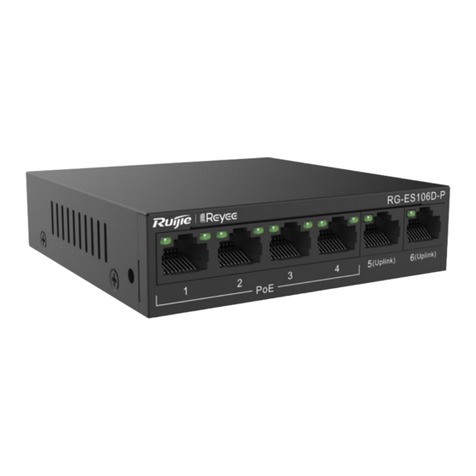
Ruijie

Ruijie RG-S29 Series Installation manual

Ruijie RG-S5750-H Series Installation and operating manual

Ruijie

Ruijie RG-S5750-H Series Installation and operating manual
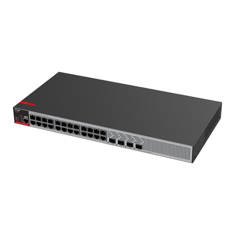
Ruijie Reyee RG-NBS5100-24GT4SFP-P Installation and operating manual

Ruijie

Ruijie Reyee RG-NBS5100-24GT4SFP-P Installation and operating manual

Ruijie RG-ES126S-LP User manual

Ruijie

Ruijie RG-ES126S-LP User manual

Ruijie RG-S2600G-I Series Instruction Manual

Ruijie

Ruijie RG-S2600G-I Series Instruction Manual

Ruijie RG-S5750-S Series Installation and operating manual
Ruijie

Ruijie RG-S5750-S Series Installation and operating manual

Ruijie RG-S6220-H Series User manual

Ruijie

Ruijie RG-S6220-H Series User manual

Ruijie RG-MF2920U Series Installation and operating manual

Ruijie

Ruijie RG-MF2920U Series Installation and operating manual

Ruijie RG-S2900 Series User manual

Ruijie

Ruijie RG-S2900 Series User manual

Ruijie RG-SF2920U Series Installation and operating manual

Ruijie

Ruijie RG-SF2920U Series Installation and operating manual

Ruijie RG-S6580-24DC8QC Installation and operating manual

Ruijie

Ruijie RG-S6580-24DC8QC Installation and operating manual

Ruijie RG-ES126S-P Installation and operating manual
Ruijie

Ruijie RG-ES126S-P Installation and operating manual

Ruijie RG-NIS3100 Series Installation and operating manual
Ruijie

Ruijie RG-NIS3100 Series Installation and operating manual
Ruijie RG-S7800C Series Installation and operating manual

Ruijie

Ruijie RG-S7800C Series Installation and operating manual
Ruijie RG-S6120 Series Installation and operating manual
Ruijie

Ruijie RG-S6120 Series Installation and operating manual
Ruijie XS-S1920 Series Installation and operating manual
Ruijie

Ruijie XS-S1920 Series Installation and operating manual

Ruijie RG-S7600 Series Installation and operating manual

Ruijie

Ruijie RG-S7600 Series Installation and operating manual

Ruijie RG-PF2920U-4GT1MS-P Series Installation and operating manual

Ruijie

Ruijie RG-PF2920U-4GT1MS-P Series Installation and operating manual

Ruijie RG-ES05 Series Installation and operating manual

Ruijie

Ruijie RG-ES05 Series Installation and operating manual

Ruijie RG-ES05 Series User manual

Ruijie

Ruijie RG-ES05 Series User manual

Popular Switch manuals by other brands

Allied Telesis AT-GS950/24 datasheet

Allied Telesis

Allied Telesis AT-GS950/24 datasheet

Draper LVC-III Wiring diagrams

Draper

Draper LVC-III Wiring diagrams

Broadcast Tools AES Switcher Sentinel 2+1 Installation and operation manual

Broadcast Tools

Broadcast Tools AES Switcher Sentinel 2+1 Installation and operation manual

Panasonic CF-VEBU07W operating instructions

Panasonic

Panasonic CF-VEBU07W operating instructions

Allied Telesis AT-8000S/48 datasheet

Allied Telesis

Allied Telesis AT-8000S/48 datasheet

Elkron RM600 quick guide

Elkron

Elkron RM600 quick guide

TESmart HKS0401A1S user manual

TESmart

TESmart HKS0401A1S user manual

DONG SUNG SENSORS DFR Series manual

DONG SUNG SENSORS

DONG SUNG SENSORS DFR Series manual

TRENDnet TEG-S2400I - DATA SHEETS user guide

TRENDnet

TRENDnet TEG-S2400I - DATA SHEETS user guide

Shure RK199S user guide

Shure

Shure RK199S user guide

Avocent AutoView 2030 brochure

Avocent

Avocent AutoView 2030 brochure

Lucci CONNECT 299045 installation instructions

Lucci CONNECT

Lucci CONNECT 299045 installation instructions

Meraki Cisco MS425 Series installation guide

Meraki

Meraki Cisco MS425 Series installation guide

Theben SELEKTA 170 top2 user manual

Theben

Theben SELEKTA 170 top2 user manual

KYLAND Ruby3A Hardware installation manual

KYLAND

KYLAND Ruby3A Hardware installation manual

schmersal G50 operating instructions

schmersal

schmersal G50 operating instructions

Siemens SITRANS LVL100 operating instructions

Siemens

Siemens SITRANS LVL100 operating instructions

ATEN KVMP CS1784A user manual

ATEN

ATEN KVMP CS1784A user manual

manuals.online logo
manuals.online logoBrands
  • About & Mission
  • Contact us
  • Privacy Policy
  • Terms and Conditions

Copyright 2025 Manuals.Online. All Rights Reserved.