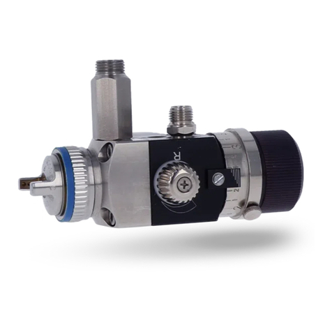
SATA graph 2 User manual

SATAgraph™2
Betriebsanleitung - Operating instructions
Instrucciones de servicio

4
3
2114
55
67
10
11
9
15
12 13
8

Betriebsanleitung SATAgraph 2
Vor Inbetriebnahme des Gerätes/der Lackierpistole ist die Betriebsanleitung vollständig und
eingehend zu lesen, beachten und einzuhalten. Danach ist diese an einem sicheren Platz, für
jeden Gerätebenutzer zugänglich, aufzubewahren. Das Gerät/die Lackierpistole darf nur von
sachkundigen Personen in Betrieb genommen werden. Bei unsachgemäßer Benutzung des
Gerätes/der Lackierpistole oder jeglicher Veränderung oder Kombination mit ungeeigneten
Fremdteilen können Sachschäden, ernste Gesundheitsschäden der eigenen Person, von frem-
den Personen und Tieren bis hin zum Tode die Folge sein. SATA übernimmt für diese Schäden
(z. B. Nichteinhaltung der Betriebsanleitung) keinerlei Haftung. Die anwendbaren Sicherheitsvor-
schriften, Arbeitsplatzbestimmungen und Arbeitsschutzvorschriften des jeweiligen Landes oder
Verwendungsgebietes des Gerätes/der Lackierpistole sind zu beachten und einzuhalten (z. B. die
deutschen Unfallverhütungsvorschriften BGR 500 (BGV D25) und BGV D24 des Hauptverbandes
der gewerblichen Berufsgenossenschaften usw.).
Vorwort
Lackierpistole nie auf sich selbst, fremde Personen oder Tiere richten. Löse- und Verdünnungsmittel
können zu Verätzungen führen. Nur die zum Arbeitsfortschritt notwendige Lösemittel- und
Lackmenge darf in der Arbeitsumgebung des Gerätes vorhanden sein (nach Arbeitsende sind
Lösemittel und Lacke in bestimmungsgemäße Lagerräume zurückzubringen). Vor jeglichen
Reparaturarbeiten muß das Gerät vom Luftnetz abgekuppelt werden. Vor jeder Inbetriebnahme,
besonders nach jeder Reinigung und nach Reparaturarbeiten, ist der feste Sitz aller
Schrauben und Muttern sowie die Dichtheit der Pistolen und Schläuche zu überprüfen.
Defekte Teile sind auszutauschen oder entsprechend instandzusetzen. Zur Erzielung bestmög-
licher Lackierergebnisse und für höchste Sicherheit nur Original-Ersatzteile verwenden. Beim
Lackieren darf im Arbeitsbereich keine Zündquelle (z.B. offenes Feuer, brennende Zigaretten,
nicht explosionsgeschützte Lampen usw.) vorhanden sein, da beim Lackieren leicht entzünd-
liche Gemische entstehen. Beim Lackieren ist den Vorschriften entsprechender Arbeitsschutz
zu verwenden (Atemschutz usw.). Bei Anwendung der Lackierpistole werden keine Vibrationen
auf Körperteile des Bedieners übertragen. Die Rückstoßkräfte sind gering. Der Einsatz die-
ses Produktes in explosionsgefährdeten Bereichen der Zone 0 ist verboten. SATA, das
SATA-Logo und/oder andere hier im Inhalt erwähnte SATA-Produkte sind entweder registrierte
Warenzeichen oder Warenzeichen der SATA GmbH & Co. KG in den USA und/oder anderen
Ländern.
Zu beachten
• Pistole mit Düse 0,25
• 4 ml Fließbecher mit Steckdeckel, Glas-
saugbecher 15 ml mit Anschluß und PVC-
Verschlußdeckel
• Gewicht: ca 96 g mit Fließbecher
ca. 125 g mit Glassaugbecher
• PVC Schlauch (Ø 4 mm) mit Schnellkupplung
und Überwurfmutter G 1/4, Länge 3m
1. Lieferausführung und technische Daten
(max. 4 bar) - je nach Lieferausführung
enthalten
• Arbeitsdruck zwischen 1,0 bis 3,0 bar
(14 bis 43 psi)
• Empfohlener Pistoleneingangsdruck
2,0 bar (26 psi)
• Max. Pistoleneingangsdruck 4 bar
(58 psi)
deutsch
I.1

Betriebsanleitung SATAgraph 2
Bei der SATAgraph 2 handelt es sich um eine abhängige „Double- Action“
Airbrush- Lackierpistole mit Zusatzfunktion, bei der Material- und Luftmenge
abhängig von einander durch betätigen des Abzugshebels (1) gesteuert und
dosiert werden kann. Durch Zurückziehen des Abzugshebels (1) wird die
Farbnadel (8) aus der Farbdüse (7) herausgezogen und gleichzeitig (abhän-
gig) der Luftkolben (9) nach unten gedrückt. Die Dosierung erfolgt über den
Abzugsweg in Abhängigkeit der Voreinstellung der Farbnadel (8), siehe Kapitel
4.5. Zusätzlich kann der Abzugshebel nach unten gedrückt werden um die so
genannte „kleine Vorluft“ zu nutzen (Bild a). Hierbei wird nur Luft freigesetzt mit
der Farbstaubreste aus der Düse entfernt werden können, oder der Farbauftrag
getrocknet werden kann. Der Lackierpistolenkopf (3) ist drehbar in Bezug auf
den Lackierpistolenkörper (Bild b), so dass die Materialzuführung wahlweise
nach oben (Fließbechervariante) oder nach unten (Saugbechervariante, Bild c)
gestellt werden kann.
Bitte Beachten:
Um eine Beschädigung der Farbnadel auszuschließen sollte die Farbnadel vor dem drehen des
Lackierpistolenkopfes (3) durch lösen der Nadelschnellspannung (13) etwas nach hinten gezogen
werden. Nach Einstellung des Lackierpistolenkopfes (3), Farbnadel (8) wieder nach vorne in die
Farbdüse (7) schieben und mit der Farbnadelschnellspannung fixieren.
2. Funktionsbeschreibung
1
2
Der Abzugshebel wird nach
hinten gezogen, dadurch wird
die Nadel nach hinten und
gleichzeitig (abhängig) das
Luftventil nach unten gedrückt.
Druckluft strömt durch die Düse
und reißt durch den entstehen-
den Unterdruck die Farbe mit.
Durch das Herunterdrücken des
Abzugshebels wird das Luftventil
geöffnet und die „kleine Vorluft“
freigesetzt.
1
2
Farbzuuß
Druckluft
Hebelmechanik
3. Aufbau
1 Abzugshebel
2 Pistolenkörper
3 Pistolenkopf
4 Fließbecher
5 Nadelkappe
I.2
+
-
1
a
b
3
c
kleine Vorluft
6 Luftdüse
7 Farbdüse mit O-Ring (nicht sichtbar)
8 Farbnadel (nicht sichtbar)
9 Luftanschluß
10 Luftkolbeneinheit (nicht sichtbar)

Betriebsanleitung SATAgraph 2
4. Inbetriebnahme
Vor jeder Inbetriebnahme, besonders nach jeder Reinigung und nach Reparaturarbeiten, ist
der feste Sitz aller Schrauben, Muttern und Verschraubungen zu überprüfen.Bei Wartungs- und
Reparaturarbeiten jeglicher Art muss das Gerät in drucklosem Zustand sein, d.h. vom Luftnetz
abgekuppelt werden und frei von Lacken und Farben sein. Die Lackierpistole wurde vor dem
Versand mit Korrosionsschutzmittel behandelt und sollte daher vor dem Gebrauch mit Verdünnung
oder Reinigungsmittel durchgespült werden. Nichtbeachtung dieses Sicherheitshinweises kann zu
Beschädigungen und Verletzungen, bis hin zum Tode, führen. SATA übernimmt keine Haftung für
eventuelle Folgen der Nichtbeachtung.
4.1 Luftdruck
Der Arbeitsdruck liegt bei ca. 1,0 - 3,0 bar. Je höher der Pistoleneingangsdruck umso besser ist
die Zerstäubung, desto schwieriger das Handling.
Bei zu geringem Druck wird in Abhängigkeit des Lackmaterials keine optimale Farbzerstäubung
erzielt. Bei einem Kompressor mit Reguliermöglichkeiten des Abgangsdruckes, kann mit unter-
schiedlichen Drücken experimentiert werden bis die gewünschten Ergebnisse erzielbar sind.
4.2 Lackmaterial
Bei Verwendung von lösemittelhaltigen Farben und Lacken ist darauf zu achten, dass diese soweit
verdünnt werden bis sie eine Konsistenz von Milch aufweisen. Andernfalls sind die Farben und
Lacke zu dick zum Brushen und es ist keine feine Zerstäubung bei ausreichendem Materialfluss
erzielbar. Auch wasserverdünnbare Farben und Lacke müssen ausreichend verdünnt werden.
Moderne Airbrushfarben und Lacke werden schon spritzfertig angeboten. Bitte beachten sie die
Angaben der Hersteller.
4.3 Richtige Einstellung des Pistoleneingangsießdruckes
Gewünschten Arbeitsdruck (1,0 - 3,0 bar) an der Druckregeleinheit des Kom-
pressors einstellen, soweit vorhanden. Diese ist direkt am Luftabgang des
Kompressors oder in eine Luftversorgungsleitung eingebaut.
Der Druckregler kann auch eine zwischengeschaltete Druckluftfiltereinheit mit
Druckminderer z. B. „SATA 0/444“ sein. Durch Ziehen am Abzugshebel wird
zuerst die Luft- und dann die Farbmenge dosiert.
-+
deutsch
I.3
11 Federhülse (nicht sichtbar) mit
Ersatz O-Ring
für den Pistolenkopf
12 Kontermutter (nicht sichtbar)
13 Farbnadelschnellspannung
(nicht sichtbar) mit Ersatz O-
Ring für Halteschraube der
Abzugshebelmechanik
14 Griffendstück
15 Glashängebecher

Betriebsanleitung SATAgraph 2
4.5 Düsensatzwechsel (ohne Werkzeug)
Der Düsensatz besteht aus der Nadelkappe (5), der Luftdüse (6), Farbdüse mit
O- Ring (7) und Farbnadel (8).
Zur Demontage des Düsensatzes, muss das Griffendstück (14) komplett
vom Lackierpistolenkörper (2) abgeschraubt werden. Nach dem Lösen der
Farbnadelschnellspannung (13) kann die Farbnadel (8) nach hinten aus dem
Pistolenkörper (2) herausgezogen werden.
Entnahme der Farbdüse (7) aus dem Pistolenkörper (2) nach Abschrauben der
Nadelkappe (5) und der Luftdüse (6).
Bitte Beachten:
Die Farbdüse (7) ist nur lose in die Luftdüse (6) eingelegt, so dass diese her-
unterfallen und beschädigt werden könnte.
Montage in umgekehrter Reihenfolge:
Nach dem Festziehen der Luftdüse (6) wird die Farbnadel (8) vorsichtig bis
zum Anschlag nach vorne hin zur Farbdüse (7) in den Pistolenkörper (2) einge-
schoben und durch Anziehen der Farbnadelschnellspannung (13) fixiert.
Farbdüse (7) nicht verkanten und Farbnadelspitze nicht beschädigen.
Achtung:
Verletzungsgefahr an der Nadelspitze, besonderst auch bei abgeschraubter
Nadelkappe (5).
Für das wechseln des Düsensatzes wird kein Werkzeug benötigt !
Bei Einbau von Fremdteilen ist Qualitätsminderung möglich und die
SATA- Garantie erlischt.
Düsensätze:
31476 0,25 für SATAgraph 2 (2 Kerben auf Farbnadel, Farb-/Luftdüse)
Die Position und somit der Punkt wenn der Abzugshebel die Mechanik der
Farbnadelführung bewegt um den Farbfluss freizugeben, kann individuell
eingestellt werden.
Durch drehen an der Federhülse (11) kann der Druckpunkt so eingestellt wer-
den das dieser früher bzw. später reagiert.
14
13
8
2
5 6
I.4
4.6 Druckpunkt festlegen
4.4 Materialmenge
Einstellen des Benutzerdefinierten Nadelabhubs. Griffendstück (14) abschrau-
ben, Farbnadelschnellspannung (13) lösen. Den Anschlag für den Abzugshebel
(1) nach Bedarf einstellen (auf Position halten), Farbnadel unter leichtem
Druck nach vorne in die Farbdüse (8) auf Anschlag schieben und danach
Farbnadel mit Hilfe der Farbnadelschnellspannung (13) fixieren. Griffendstück
(14) anschrauben.
13
2
7
11

Betriebsanleitung SATAgraph 2
Griffendstück (14) abschrauben, Farbnadelschnellspannung (13) lösen und
Farbnadel (8) nach hinten herausziehen.
Lackierpistolenkopf (3) vom Lackierpistolenkörper (2) abschrauben.
Vor dem Zusammenbau sollte der O-Ring der zwischen Lackierpistolenkopf
(3) und Lackierpistolenkörper (2) sitzt gefettet bzw. bei Beschädigung
ersetzt werden. Zusammenbau erfolgt in umgekehrter Reihenfolge (auf der
Federhülse (11) befindet sich ein Ersatz O-Ring für den Pistolenkopf).
Bitte wenden Sie niemals Gewalt an. Große Rohrzangen, Schweißbrenner usw. sind ungeeignete
Hilfsmittel. Eine sachgemäße Reparatur kann in vielen Fällen nur mit Spezialwerkzeugen durch-
geführt werden. Beschränken Sie sich in diesem Fall auf die Feststellung der Schadensursache
und überlassen Sie die Behebung unserem Kundendienst. Nach einer Selbstdemontage erlischt
die Haftung für das einwandfreie Funktionieren der Pistole.
a) Airbrush-Lackierpistole bei jedem Farbwechsel reinigen.
b) Lackierpistole mit Wasser, Airbrushreiniger oder mit entsprechendem Lösungsmittel
spülen. Bei sehr pigmenthaltigen Farben und Lacken sammeln sich schnell Farb- und
Lackreste sowohl auf der Nadel als auch im Bereich der Nadelkappe an.
c) Nach Abschluss der Arbeit ist eine gründliche Reinigung der mit Lack und Farbe
kontaktierten Teilen erforderlich.
d) Die eingebaute Luftkolbeneinheit (8) sollte nach Möglichkeit nicht zerlegt werden.
Gelegentlich Hebelmechanik und Nadel im Bereich der Hebelmechanik dünn mit
silikonfreiem Pistolenfett (Best.-Nr. 48173) einfetten.
Nadelspitze und den Bereich der Luft- und Farbdüse nicht fetten!
6. Reinigung und Wartung
Wichtiger Hinweis:
Pistole kann mit Löse- oder Reinigungsmitteln von Hand oder in einer konventionellen
Pistolenwaschmaschine gereinigt werden.
Folgende Maßnahmen beschädigen die Pistole/Einrichtungen und können ggf.
zum Verlust des Explosionsschutzes und zum völligen Verlust von Gewähr-
leistungsansprüchen führen:
- Einlegen der Pistole in Löse- oder Reinigungsmittel länger als
für die Reinigung selbst erforderlich
- Nichtentnehmen der Pistole aus der Pistolenwaschmaschine
nach Beendigung des Waschprogramms
- Reinigen der Pistole in Ultraschallreinigungssystemen
5. Demontage des Lackierpistolenkopfes
3
I.5
deutsch

Betriebsanleitung SATAgraph 2
8. Ersatzteile (siehe Ersatzteilzeichnung am Ende des Heftes)
•
7. Mögliche Funktionsstörungen
Störung Ursache Abhilfe
1. Pistole tropft Fremdkörper zwischen Farb-
nadel und Farbdüse verhindert
Abdichtung
Farbnadel und Farbdüse aus-
bauen, reinigen oder neuen
Düsensatz einsetzen.
Einstellung der Farbnadel
korrigieren.
2. Spritzbild ist schlecht Verschmutzung oder Abnutz-
ung der Teile
Farbdüse, Farbnadel oder
Luft-düse reinigen. Teile
ersetzen
3. Strahl flattert
4. Material sprudelt oder
„kocht“ im Farbbecher
Leckage an der Düsendichtung
- Nicht genügend Material
im Behälter
- Farbdüse nicht angezogen
- Material nachfüllen
- Teile entsprechend anziehen
- Dichtfläche an Dichtung
und Körper reinigen
- Luftdüse etwas fester ziehen
- Teile ersetzen
Pos. Nr. ID.-Nr. Benennung
31476 Düsensatz SATAgraph 2
32276 Reparaturset
*138909 O-Ring Set für Farbdüse (5 St.)
136020 Abzugshebel
431781 Fließbecher 4 ml mit Deckel
4a 32029 Packung mit 3 Deckeln für Fließbecher 4 ml
535964 Nadelkappe SATAgraph 2
932615 Packung mit 3 Kupplungsnippeln und Dichtungen
134791 Gewebeschlauch, kpl. 2,5 m
14 33001 Griffendstück
15 33019 Glasbecher 15 ml und Deckel mit Saugrohr
15a 33092 Packung mit 5 Glasbechern 15 ml und 5 Blinddeckeln
plus 1 Deckel mit Saugrohr
I.6

Betriebsanleitung SATAgraph 2
9. Garantiebedingungen
Für Lackierpistolen leisten wir eine Garantie von 12 Monaten, die mit dem Tage des Verkaufs an den
Endabnehmer beginnt. Die Garantie erstreckt sich auf den Materialwert von Teilen mit Fabrikations-
und Materialfehlern, die sich innerhalb der Garantiezeit herausstellen. Ausgeschlossen sind Schäden,
die durch ungeeignete oder unsachgemäße Verwendung, fehlerhafte Montage bzw. Inbetriebsetzung
durch den Käufer oder durch Dritte, natürliche Abnutzung, fehlerhafte Behandlung oder Wartung,
ungeeignete Spritzmaterialien, Austauschwerkstoffe und chemische Einflüsse wie Laugen und Säuren,
elektrochemische oder elektrische Einflüsse entstehen, sofern die Schäden nicht auf ein Verschulden
von uns zurückzuführen sind. Schmirgelnde Spritzmaterialien, wie z.B. Bleimennige, Dispersionen,
Glasuren, flüssige Schmirgel o.ä. verringern die Lebensdauer von Ventilen, Packungen, Pistole und
Düse. Hierauf zurückzuführende Verschleißerscheinungen sind durch diese Garantie nicht gedeckt.
Das Gerät ist unverzüglich nach Empfang zu kontrollieren. Offensichtliche Mängel sind innerhalb
von 14 Tagen nach Empfang des Gerätes der Lieferfirma oder uns schriftlich mitzuteilen, andernfalls
erlischt das Recht auf Garantieleistungen. Weitergehende Ansprüche jeglicher Art, insbesondere auf
Schadenersatz, sind ausgeschlossen. Das gilt auch für Schäden, die bei Beratung, Einarbeitung und
Vorführung entstehen. Wünscht der Käufer sofortige Reparatur oder Ersatz, bevor festgestellt ist, ob
von uns eine Ersatzpflicht besteht, so erfolgt die Ersatzlieferung oder Reparatur gegen Berechnung
und Bezahlung des jeweiligen Tagespreises. Stellt sich bei der Überprüfung der Mängelrüge heraus,
daß ein Garantieanspruch besteht, erhält der Käufer für die berechnete Reparatur oder Ersatzlieferung
eine Gutschrift entsprechend der Garantieleistung. Teile, für die Ersatz geliefert wurde, gehen in unser
Eigentum über. Mängelrügen oder sonstige Beanstandungen berechtigen den Käufer bzw. Auftraggeber
nicht, die Bezahlung zu verweigern oder zu verzögern. Versand des Gerätes hat an uns spesenfrei zu
erfolgen. Montagekosten (Arbeitszeit- und Fahrtkosten) sowie Fracht- und Verpackungsspesen können
wir nicht übernehmen. Hier gelten unsere Montagebedingungen. Garantieleistungen bewirken keine
Verlängerung der Garantiezeit. Die Garantie erlischt bei Fremdeingriffen.
Achtung! Bei Verwendung von Löse- und Reinigungsmitteln auf der Basis halogenisier-
ter Kohlenwasserstoffe. wie z.B. 1,1,1-Trichloräthan und Methylen-Chlorid, können an
Aluminiumbecher, Pistole sowie galvanisierten Teilen chemische Reaktionen auftreten (1,1,1-
Trichloräthan mit geringen Mengen Wasser ergibt Salzsäure). Die Teile können dadurch oxydieren,
im extremen Fall kann die Reaktion explosionsartig erfolgen. Verwenden Sie deshalb für Ihre
Farbspritzgeräte nur Löse- und Reinigunsmittel, die die obengenannten Bestandteile nicht enthal-
ten. Zur Reinigung auf keinen Fall Säure, Lauge (Basen, Abbeizer etc.) verwenden.
Die Lackierpistolen der Firma SATA sind entwickelt, konstruiert und gefertigt in Übereinstimmung
mit der EG-Richtlinie 98/37/EG, 94/9/EG. Es wurden dabei folgende harmonisierte Normen angewandt:
DIN EN 292, Sicherheit von Maschinen, Geräten und Anlagen, DIN EN 1953, DIN 31000, DIN 31001
Teil 1, BGR 500 (BGV D25), BGV D24 und bei Bedarf die ZH 1/406, ZH 1/375 und ZH 1/181. Die techni-
sche Dokumentation ist vollständig vorhanden und die zur Lackierpistole gehörende Betriebsanleitung
liegt in der Originalfassung sowie in der Landessprache des Anwenders vor.
SATA GmbH & Co. KG
Geschäftsführer
10. EU-Konformitätserklärung
I.7
deutsch
Operating Instructions SATAgraph 2
Prior to putting the unit/paint spray gun into operation, read the operating instructions comple-
tely and thoroughly. The stipulations contained therein are to be respected in any case. After
that, the operating instructions are to be stored in a safe place, accessible for every user of the
equipment. The unit/paint spray gun may only be put into operation by persons familiar with its
use. Inappropriate use of the unit/paint spray gun, modification of any kind or combination with
inappropriate other parts may cause material damage, serious hazard to the user‘s, other person‘s
or animal‘s health or even death. SATA shall not take any responsibility for such damages (e.g.
failure to respect the stipulations laid out in the operating instructions). The applicable safety,
workplace and worker health protection regulations of the respective country or area/district in
which the system/the paint spray gun is used are to be respected in any case (e.g. the German
Rules for the Prevention of Accidents BGR 500 (BGV D25) and BGV D24 issued by the Central
Office of the Professional Trade Associations, etc.).
Preface
Never point paint spray guns at yourself, at other persons or animals. Solvents and thinners can
cause burns. Only the respective quantities of solvents and paints required for work progress may
be present in the direct surroundings of the unit (after work, solvents and paints are to be returned
to their assigned storage rooms). Prior to any repair work the unit must be disconnected from the
air supply. Prior to putting the unit into operation, especially after each cleaning and each
repair work, check all screws and nuts for tight fit, as well as the sealing performance of
the spray guns and hoses. Defective components must be replaced or repaired accordingly. To
obtain best possible coating results, and for maximum safety, only use original spare parts. No
sources of ignition (e.g. open flames, burning cigarettes, lamps without ex-protection etc.) may be
present during painting, as easily flammable mixture are generated during the painting process.
Occupational safety regulations must be applied when painting (respiratory protection, etc.). No
vibration is transmitted to the upper parts of the operator‘s body during use of the paint spray
gun. Recoil forces are negligible. The use of this product in explosion hazard areas Zone 0
is prohibited.
SATA, the SATA Logo and/or other SATA products referenced herein are either registered trade-
marks or trademarks of SATA GmbH & Co. KG in the U.S. and/or other countries. The names of
companies and products mentioned herein may be the trademarks of their respective owners.
To be noted
• Gun with nozzle 0.25
• 4 ml gravity flow cup with plug-in lid, 15 ml
glass siphon cup with connection and PVC
lid
• Weight: approx. 96 g with gravity flow cup,
125 g with glass siphon cup
• PVC hose (Ø 4 mm) with quick coupling and
sleeve nut G 1/4, length 3m
1. Features and technical data
(max. 4 bars) - included according to scope
of supplies
• Operating pressure between 1.0 and 3.0
bars (14 to 43 psi)
• Recommanded un inlet pressure
2.0 bars (26 psi)
• Max. gun inlet pressure 4 bars
(58 psi)
II.1

Operating Instructions SATAgraph 2
The SATAgraph 2 is a semi double-action airbrush that allows control and
adjustment of material flow and air volume (both at the same time only) by
activating the trigger (1). By pulling the trigger (1), the paint needle (8) is
pulled back from the paint nozzle (7), and at the same time the air piston (9) is
pushed down. The material flow is adjusted with the trigger, depending on the
pre-adjustment of the paint needle (8); see chapter 4.5.
Alternatively, the airbrush can be triggered to make use of „pre-air“. In this
case, the gun only releases air that may be used for removing paint dust from
the nozzle or to dry paint.
The paint spray gun head (3) can be turned relative to the gun body; to convert
the airbrush from gravity to a siphon cup gun or vice versa.
Please note:
In order to avoid damage to the paint needle, it should be pulled to the rear a
little by loosening the needle lock nut (13) before the gun head (3) is turned.
After adjusting the gun head (3), push the paint needle (8) back into the paint nozzle (7) and
tighten it with the paint needle lock nut.
2. Functional Description
1
2
The trigger is pulled towards
the back, which simultaneous-
ly takes the needle along and,
depending on this movement,
pushes down the air valve.
Compressed air streams through
the nozzle and carries along the
paint due to the arising vacuum
effect.
By pushing down the trigger
the air valve is opened and the
„small pre-air“is released.
1
2Paint supply
Compressed air
Lever mechanism
3. Construction
1 Trigger
2 Gun body
3 Airbrush head
4 Gravity flow cup
5 Needle cap
+
-
1
a
b
3
c
„small pre-air“
6 Air cap
7 Paint nozzle with „O“ ring (not visible)
8 Paint needle (not visible)
9 Air connection
10 Air piston unit (not visible)
english
II.2

Operating Instructions SATAgraph 2
4. Putting into Operation
Before putting into operation, and especially after each cleaning and any repair work, check to see
that all screws and nuts are tight. The paint spray gun has been treated with an anticorrosive agent
before leaving the factory and must therefore be flushed out thoroughly with thinner before. For
servicing/repair work of any kind, the system must be devoid of pressure, i.e. disconnected from
the air supply. Failure to respect this safety warning may result in damage and injuries, even death
at worst. SATA does not take any responsibility for possible results of such failure.
4.1 Air Pressure
The operating pressure is approx. 1 - 3 bars. The higher the gun inlet pressure, the better the
atomization and the more difficult the handling. When the pressure is too low, no optimum paint
atomization is achieved, depending on the paint material.
If the compressor allows adjustment of the output pressure, different pressures may be tried until
the desired results are achieved.
4.2 Paint Material
When using solvent-based paints and lacquers it must be ensured to thin them down until they
reach the consistency of milk. Otherwise the paints and lacquers are too thick to be „brushed“,
and it is not possible to achieve a fine atomization with sufficient material flow. Waterborne paints
and lacquers, too, must be thinned sufficiently.
Modern airbrush colors and lacquers are offered ready for spraying. Please respect the material
manufacturers‘ stipulations.
4.3 Correct Adjustment of the Gun Inlet Pressure
Adjust required operating pressure (1 - 3 bars) at the pressure regulation unit
of the compressor, as far as available. This unit is integrated directly at the
compressor air outlet, or into an air supply pipe. The pressure regulator can
also be a compressed air filter unit with pressure regulator, e.g. „SATA 0/444“,
connected in between. By pulling the trigger, the air volume is regulated first,
then the paint volume.
-+
11 Spring sleeve (not visible) with
spare O-ring for the gun head
12 Counter nut (not visible)
13 Paint needle lock nut
(not visible) with spare O-ring for the
trigger mechanism lock nut
14 Handle end piece
15 Glass siphon cup
II.3

Operating Instructions SATAgraph 2
4.5 Nozzle Set Replacement (without tool)
The nozzle set consists of needle cap (5), air cap (6), paint nozzle with „O“ ring
(7) and paint needle (8). To remove the nozzle set, the handle end piece (14)
must be completely separated from the airbrush body (2). After loosening the
paint needle lock nut (13), the paint needle (8) can be pulled out of the gun
body (2) toward the rear.
The paint nozzle (7) can be removed from the gun body (2) after unscrewing
the needle cap (3) and the air cap (6).
Please note:
The paint nozzle (7) is inserted only loosely into the air cap (6) - danger of
damage by dropping.
Assembly in the opposite sense:
After tightening the air cap (6), the paint needle (8) is carefully pushed into the
gun body (2) towards the paint needle (7) at the front until bedstop and fixed
by tightening the paint needle quick tightening (13). Do neither cant the paint
nozzle (7) nor damage paint needle tip.
Attention:
Danger of hurting at the needle tip, especially if the needle cap (5) is screwed
off. When foreign parts are integrated the quality level may decline and
the SATA warranty expires.
Nozzle sets:
31476 0,25 for SATAgraph 2 (2 grooves on paint needle,
paint nozzle/air cap)
The trigger position in which the trigger moves the paint needle mechanism in
order to release paint can be adjusted according to your requirements.
By turning the spring sleeve (11), the pressure point can be adjusted to release
paint material in the position that you require.
14
13
8
2
5 6
4.6 Fixing the Pressure Point
4.4 Material Flow
Adjusting the user-defined needle stroke. Unscrew handle end piece (14) and
loosen paint needle lock nut (13). Adjust trigger (1) dead stop according to
your requirements (hold in this position). Apply slight pressure while pushing
the paint needle into the paint nozzle (8) until reaching the dead stop position.
Then tighten paint needle with the lock nut (13). Finally screw on handle end
piece (14).
13
2
7
11
english
II.4

Operating Instructions SATAgraph 2
Unscrew handle end piece (14), loosen paint needle lock nut (13) and pull out
paint needle (8) toward the rear.
Unscrew paint spray gun head (3) from gun body (2).
Prior to assembly, the O-ring located between the gun head (3) and the gun
body (2) should be lubricated or replaced if damaged.
Assembly must be performed exactly in reverse.
(a spare O-ring for the gun head is attached to the spring sleeve (11)
Never use force. Using improper tools such as pipe wrench, gas torch, etc. will void any warranty.
In many cases proper repairs can only be carried out with the aid of special tools. In such cases,
limit yourself to establishing the cause of the problem and leave the repairs to the service depart-
ment. We refuse to accept liability for perfect functioning of the spray gun if it is disassembled by
the customer.
a) Clean airbrush paint spray gun during every color change.
b) Flush paint spray gun with water, airbrush cleaner or corresponding solvent. With
paints and lacquers having a high pigment content paint and lacquer remainders
quickly deposit on the needle and around the needle cap.
c) After finishing the work, thorough cleaning of the parts in contact with lacquer and
paint is required.
d) If possible, the integrated air piston unit (8) should not be dismantled.
Occasionally grease lever mechanism and needle in the area of the lever
mechanism with a thin layer of silicone-free gun grease (Order No. 48173).
Do not grease the needle tip and the area of air cap and paint nozzle!
Important Notice:
Gun may be cleaned with solvent or cleaning agents manually or in a conventional gun
washing machine.
The following actions damage the gun/system, may lead to the loss of the explosion-
proofness approval and entirely annull any warranty claims:
- Immersing the gun in solvent or cleaning agents, or for a period longer than required
for the cleaning process as such
- Storing the gun inside the gun washing machine
- Cleaning the gun by means of ultrasound cleaning systems
6. Cleaning and Maintenance
5. Removing the Paint Spray Gun Head
3
II.5

Operating Instructions SATAgraph 2
7. Spare parts (see spare part drawing at the end of this booklet)
•
Pos. No. Part.No. Description
31476 Nozzle set SATAgraph 2
32276 Repair kit
*138909 “O” ring kit for paint nozzle (pack of 10)
136020 Trigger
431781 Gravity flow cup 4 ml with lid
4a 32029 Pack with 3 lids for gravity flow cup 4 ml
535964 Needle cap SATAgraph 2
932615 Pack with 3 coupling nipples and sealings
134791 Tissue hose, cpl. 2.5 m
14 33001 Handle end piece
15 33019 15 ml glass cup with lid and suction pipe
15a 33092 Pack of 5 - 15 ml glass cups with 5 lids, and 1 lid with suction pipe
6. Possible failures in operation
Trouble Cause Repair
1. Gun leaks Foreign substances between
fluid tip and needle prevent
sealing
Remove and clean fluid need-
le and fluid nozzle or install
new nozzle set. Correct paint
needle adjustment.
2. Spray pattern is bad Soiling and wear of parts Clean paint nozzle, paint
needle or air cap. Replace
parts.
3. Paint spray flutters
4. Material bubbles or
„boils“ in paint cup
Leakage at the nozzle sealing
- Too little material in cup
- Fluid nozzle not tight self-
adjusting
- Refill material
- Tighten parts
- Clean sealing surface at
sealing and body
- Tighten air cap a little more
strongly
- Replace parts
english
II.6

Operating Instructions SATAgraph 2
9. Guarantee conditions
During the period of twelve (12) months from the date of original purchase, SATA will repair or replace
the product without charge for parts or labour subject to the following conditions. The warranty covers
the value for production parts or defects in material during the warranty period. The warranty does not
include damages caused by improper handling, normal wear and tear, mechanical damages, faulty
assembly, improper maintenance, unusual spray materials substitute materials, chemicals such as
alkaline solutions and acids, electro-chemical or electric influences, as far as this damage is not the
result of any error committed by us. Abrasive spray material such as red lead and liquid grinding mate-
rial etc. reduce the lifetime of valves, packings, guns and nozzles. Wear and tear damage caused by
this are not covered in this warranty. Units should be inspected upon delivery by the consumer. Obvious
damage must be reported within 14 days of receipt of the unit to the supplier to avoid loss of the right
to claim notice of defects.
Additional claims such as compensation are excluded. This refers as well to damages caused during
meetings , training sessions, or demonstrations. Should the consumer require immediate repair or
replacement before a determination of whether the affected unit is covered by the warranty, the repair
or the replacement will be made and charged at the current prices. If it is determind that the item is
covered by the warranty, a credit will be issued for the repair or replacement. Replaced parts become
the property of SATA or their distributor. Notice of defects or other claims do not entitle the consumer
to delay or refuse payment. Returned merchandise to SATA must be sent prepaid. All service charges,
freight and handling charges are to be paid by the consumer. The charges made will be in accordance
with the currently existing pricing. Suretyships may not prolong the warranty period. This warranty
terminates upon unauthorized inference.
Caution! When using solvents and cleaning agents based on halogenated hydrocarbons e.g.
1.1.1-trichlorethylene and methylene chloride, chemical reactions can occur on the aluminium
cup, gun and galvanized components (small quantities of water added to 1.1.1-trichlorethyelene
produce hydrochloric acid). This can cause oxidation of the components; in extreme cases, the
reaction can be explosive. Therefore, only use solvents and cleaning agents for your paint gun
which do not contain the substances named above. You must never use acid, alkaline solutions/
lye or stripping agents for cleaning.
Paint spray guns made by SATA have been developed, designed and manufactured in accordance with
EC directive 98/37/EC, 94/9/EC. The following harmonized Standards have been applied during this
process: DIN EN 292, Sicherheit von Maschinen, Geräten und Anlagen (Safety of Machines, Appliances
and Systems), DIN EN 1953, DIN 31000, DIN 31001 Teil (Part) 1, BGR 500 (BGV D25), BGV D24, and,
if required, ZH 1/406, ZH 1/375 and ZH 1/181.
The technical documentation is provided in full and the operating instructions for the spray gun are
supplied in the original version and in the national language of the user.
SATA GmbH & Co. KG
President
10. EC Declaration of Conformity
II.7

Instrucciones de servicio SATAgraph 2
español
III.1
Antes de poner en marcha el aparato o la pistola de barniz, debe leerse, tenerse en cuenta y
cumplirse el manual de servicio en su totalidad y concretamente. Seguidamente deberá guardarse
en lugar seguro, accesible a todos los usuarios del aparato. El aparato o la pistola de embarnizar
sólo debe ser puesta en funcionamiento por técnicos. Si se utiliza de forma inadecuada el aparato
o la pistola de embarnizar o se cambiase o combinase con piezas ajenas inadecuadas, pueden
aparecer daños materiales, graves secuelas sanitarias en el propio cuerpo, en personas ajenas y
animales, hasta incluso la muerte. SATA no se responsabiliza de estos daños (p.ej. incumplimien-
to de las instrucciones de servicio). Deben tenerse en cuenta y cumplirse las normas de seguri-
dad, las disposiciones del puesto de trabajo y las normas de protección laboral del país respectivo
o de la zona de aplicación del aparato o la pistola de embarnizar (p.ej. las normas alemanas de
protección contra accidentes BGR 500 (BGV D25) y BGV D24 de la Asociación Central de las
Mutuas Laborales Industriales, etc.).
Prefacio
No dirigir la pistola de embarnizar nunca sobre sí mismo, personas ajenas o animales. Los disol-
ventes y los agentes de dilución pueden producir corrosión. En el entorno del aparato sólo debe
existir la cantidad de disolvente y de barniz necesaria para el progreso del trabajo. Después de
finalizar el trabajo, deben devolverse los disolventes y los barnices a las naves de almacenami-
ento dadas. Antes de realizar cualquier reparación, debe desacoplarse el aparato de la red de
aire. Antes de la puesta en funcionamiento, especialmente después de cada limpieza y
después de reparaciones, debe comprobarse que los tornillos estén fijamente asentados
y que las pistolas y los tubos sean estancos. Las piezas defectuosas deben cambiarse o
repararse convenientemente. Para lograr el mejor resultado posible de embarnizado y para la
máxima seguridad, utilizar sólo piezas de recambio originales. Al embarnizar, en la zona de traba-
jo no debe existir ninguna fuente de ignición (p.ej. fuego abierto, cigarrillos quemando, lámparas
no protegidas contra detonaciones, etc.), ya que al embarnizar se producen gases fácilmente
inflamables. Al embarnizar debe utilizarse una protección laboral correspondiente a las normas
(protección respiratoria, etc.). Al aplicar una pistola de embarnizado, no se transmiten vibraciones
a partes del cuerpo del operario y las fuerzas de retroceso son muy bajas.
Está prohibido el uso de este producto en la zona bajo peligro de explosión 0.
SATA, el logotipo de SATA y otros productos SATA, mencionados en este contexto, son marcas
registradas o marcas de la empresa SATA GmbH & Co. KG en los EE.UU. o en otros países.
A tener en cuenta
• Pistola con boquilla 0,25
• Depósito de gravedad de 4 ml con tapa
enchufable, depósito de aspiración en vidrio
de 15 ml con ceonexión y tapa de cierre de
PVC
• Peso: aprox. 96 g con depósito de gravedad
aprox. 125 g con depósito de
aspiración en vidrio
•
Manguera de PVC (Ø 4 mm) con acoplamiento
1. Versión de envío y características técnicas
rápido y tuerca de unión G 1/4, longitud 3m
(max. 4 bares) - contenido conforme la
versión de entrega
• Presión de trabajo entre 1,0 y 3,0 bares
(14 hasta 43 psi)
• Presión de entrada de la pistola
recomendada 2,0 bar (26 psi)
• Presión de entrada de la pistola
máxima 4 bares (58 psi)

Instrucciones de servicio SATAgraph 2
III.2
En caso de la SATAgraph 2 se trata de una pistola de pintura airbrush “Double-
Action” dependiente con función adicional en la cual la cantidad de material y
de aire puede ser controlada y dosificada dependientemente a través de pre-
sionar la palanca del gatillo (1). A través de la tracción de la palanca del gatillo
(1) la aguja de pintura (8) es sacada de la boquilla de pintura (7) y al mismo
tiempo el pistón de aire (9) es presionado (dependientemente) hacia abajo.
La dosificación se realiza a través del camino de salida en dependencia de la
regulación completa de la aguja de pintura (8),véase el capítulo 4.5.
Adicionalmente la palanca del gatillo puede ser apretada hacia abajo para
utilizar el así llamado „aire preliminar pequeño”. Con esto, sólo sale aire con
lo qual pueden ser eleminados restos de polvo de la pintura de la boquilla o
puede secar la aplicación de la pintura. La cabeza de la pistola de pintura (3)
es giratoria en relación al cuerpo de la pistola de pintura de modo que la con-
ducción de material puede ser regulada alternativamente hacia arriba (variante
de depósito de gravedad) o hacia abajo (variante de depósito de aspiración).
Por favor tenga en cuenta:
Para evitar un daño de la aguja de pintura, la aguja de pintura debría ser tirada un poco hacia
para atrás antes de girar la cabeza de la pistola de pintura (3) a tráves de soltar el preajustamiento
rápido de la aguja (13). Después de ajustar la cabeza de la pistola de pintura (3), meta la aguja
de pintura (8) otra vez hacia delante en la boquilla de pintura (7) y fijela con el preajustamiento
rápido de la aguja de pintura.
2. Descripción funcional
1
2
La palanca del gatillo es tirada
hacia atrás, con eso la aguja
es empujada hacia atrás y
al mismo tiempo (dependien-
temente) la vávula de aire
es empujada hacia abajo. Aire
comprimido corre por la boquil-
la y arrasta la pintura a través
de la presión hipoatmosférica
producida.
A través de apretar la palanca
del gatillo hacia abajo, la vávula
de aire es abierta y el “aire preli-
minar pequeño” es libertado.
1
2
Flujo de material
Aire comprimido
Mecánica de palancas
3. Componentes
1 Palanca del gatillo
2 Cuerpo de la pistola
3 Cabeza de la pistola de pintura
4 Depósito de gravedad
5 Tapa de la aguja
+
-
1
a
b
3
c
“aire preliminar pequeño”
6 Boquilla de aire
7 Boquilla de pintura con junta tórica (no es
visible)
8 Aguja de pintura (no es visible)
9 Conexión de aire
10 Unidad de pistones de aire (no es visible)

Instrucciones de servicio SATAgraph 2
español
III.3
4. Puesta en funcionamiento
Antes de cada puesta en funcionamiento, especialmente después de cada limpieza y después de reparacio-
nes, debe comprobarse que todos los tornillos y tuercas estén firmemente asentados. La pistola de pintura
es tratada, antes de su envío, con agente anticorrosivo, por lo cual es recomendado lavarla cuidadosamen-
te con diluyente o detergente antes de utilizarla. Si se realizan trabajos de mantenimiento o reparaciones
del tipo que fuesen, el aparato debe estar despresurizado, es decir, desacoplado del sistema de aire. Si
no se tiene en cuenta esta instrucción de seguridad, pueden suceder averías y accidentes, hasta mortales.
SATA no se responsabiliza de eventuales secuelas debidas a incumplimiento de las normas.
4.1 Presión de aire
La presión de trabajo es de aproximadamente 1 - 3 bares. Cuanto más alta la presión de entrada
de la pistola mejor es la pulverización y más dificil es el manejo. Cuando hay presión muy poca no
se obtiene una pulverización de la pintura óptima en dependencia del material de pintura. En caso
de un compresor con posibilidades de regulación de la presión de salida se puede experimentar
con presiones diferentes hasta que los resultados deseados sean obtenidos.
4.2 Material de pintura
En caso de uso de pinturas y lacas con disolventes se debe tener en cuenta que estas son
diluidas hasta teneren una consistencia igual a leche. En caso contrario las pinturas y lacas son
gruesas a más para el Brush y no se puede obtener una pulverización fina con un flujo de material
suficiente. Pinturas y lacas que pueden ser diluidas con agua también tienen que ser diluidas
suficientemente. Pinturas y lacas modernas para la aereografía ya son ofrecidas listas para pintar.
Por favor tenga en cuenta las indicaciones del fabricante.
4.3 Regulación correcta de la presión de entrada de la pistola
Regule la presión de trabajo deseada (1 - 3 bares) en la unidad reguladora de la
presión del compresor, si existe. Esta está montada directamente en la salida
del aire del compresor o en una junta de aprovisionamiento de aire. El regula-
dor del aire también puede ser una unidad de filtros de presión de aire interca-
lado con reductor de presión p.ej. “SATA 0/444”. A través de la tracción de la
palanca del gatillo primero es dosifcada la cantidad de aire después la cantidad de pintura.
-+
11 Estuche de resorte (no es visible)
con junta tórica de sustitución
para la cabeza de la pistola
12 Contratuerca (no es visible)
13 Preajustamiento rápido de la
aguja de pintura (no es visible)
con junta tórica de sustitución para
tornillo de soporte de la mécanica de la
palanca del gatillo
14 Pieza final del mango
15 Depósito colgante en vidrio

Instrucciones de servicio SATAgraph 2
III.4
4.5 Cambio del juego de boquillas (sin herramienta)
El juego de boquillas consiste de la tapa de la aguja (5), de la boquilla de aire
(6), de la boquilla de pintura con junta tórica (7) y de la aguja de pintura (8).
Para desmontar el juego de boquillas, la pieza final (14) tiene que ser destor-
nillada completamente del cuerpo de la pistola (2). Después de destornillar
el preajustamiento rápido de la aguja de pintura (13), la aguja de pintura (8)
puede ser sacada por atrás del cuerpo de la pistola (2).
La toma de la boquilla de pintura (7) del cuerpo de la pistola (2) se efectua
después de desatornillar la tapa de la aguja (5) y de la boquilla de aire (6).
Por favor tenga en cuenta:
La boquilla de pintura (7) está metida suelta en la boquilla de aire (6) de modo
que esta podría caer y ser deteriorada.
Montaje en orden inversa:
Después de fijar la boquilla de aire (6) y la tapa de la aguja, la aguja de pintura
(8) está metida con cuidado hacia el tope en dirección de la boquilla de pintura
(7) en el cuerpo de la pistola (2) y fijada apertando el preajustamiento rápido
de la aguja de pintura (3). No bloque la boquilla de pintura (7) y no dañe la
punta de la aguja de pintura.
Atención:
Peligro de herirse en la punta de la aguja, especialmente cuando la tapa está
desatornillada (5). Durante el montaje de piezas procedentes de otras
empresas una reducción de la calidad es posible y la garantía SATA
expira.
Juegos de boquillas:
31476 0,25 para SATAgraph 2 (2 entalladuras en la aguja de pintura,
boquilla de pintura y de aire)
La posición y con eso el punto cuando la palanca del gatillo mueve la mecánica
de la guía de la aguja de pintura para desbloquear el flujo de pintura puede ser
ajustado individualmente.
A través de girar el estuche de resorte (11) el punto del disparador puede ser
ajustado de tal manera que este reaja antes o sea más tarde.
14
13
8
2
5 6
4.6 Fijar el punto del disparador
4.4 Cantidad del material
Regulación del curso de la aguja definida para el usuario: Destornille la pieza
final del mango (14), solte el preajustamiento rápido de la aguja de pintura
(13). Si es necesario ajuste el tope para la palanca del gatillo (1) (mantener
en la posición), meta la aguja de pintura bajo leve presión en la frente de la
boquilla de pintura (8) y después fije la aguja de pintura con la ayuda del prea-
justamiento rápido de la aguja de pintura (13). Atornille la pieza final del mango (14).
13
2
7
11
Table of contents
Languages:
Other SATA Paint Sprayer manuals

SATA
SATA spray master RP User manual

SATA
SATA SATAJET 3000 K RP/HVLP User manual

SATA
SATA HRS User manual

SATA
SATA minijet 4400 B User manual

SATA
SATA Econoline 1.0 User manual

SATA
SATA BVD User manual

SATA
SATA SATAjet 3000 B RP User manual

SATA
SATA SATAjet 3000 B RP User manual

SATA
SATA SATAjet 3000 A HVLP User manual

SATA
SATA dolphin 1420 User manual