manuals.online logo
Brands
  1. Home
  2. •
  3. Brands
  4. •
  5. Sauder
  6. •
  7. Indoor Furnishing
  8. •
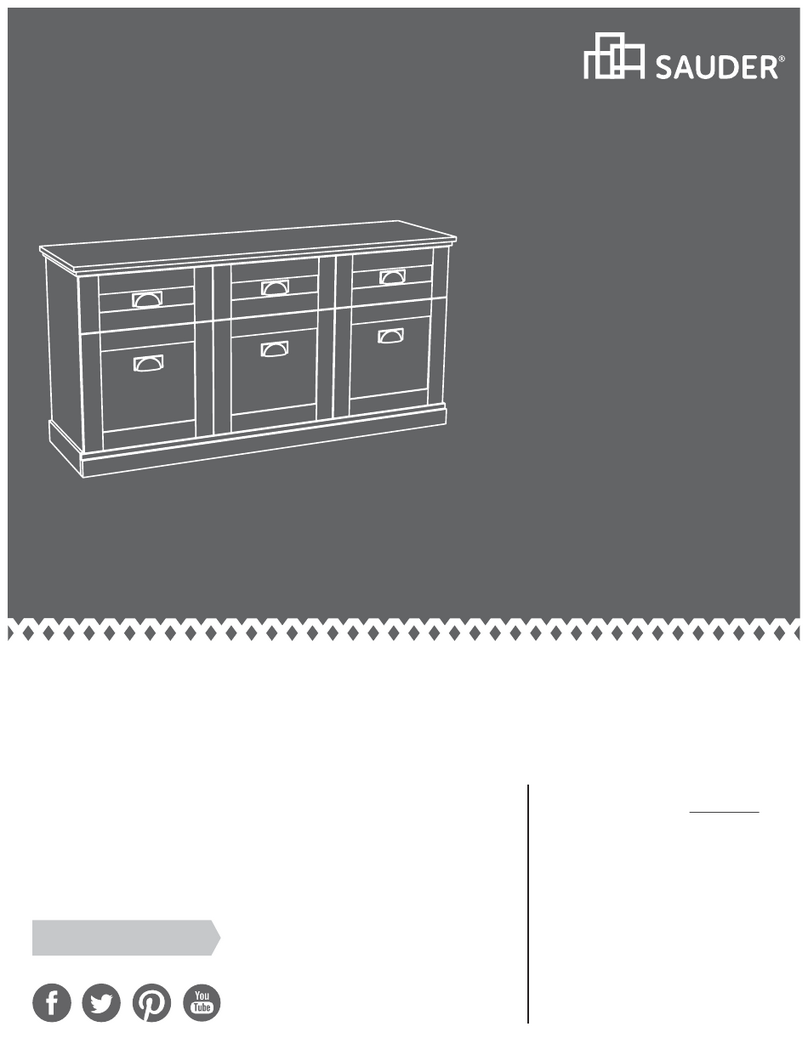
  9. Sauder 414817 User manual

Sauder 414817 User manual

PLEASE CONTACT US
BEFORE RETURNING
YOUR UNIT TO THE STORE
1-800-523-3987
www.sauder.com
Made in the USA
Archbold, OH
NOTE: THIS INSTRUCTION BOOKLET CONTAINS
IMPORTANT SAFETY INFORMATION.
PLEASE READ AND KEEP FOR FUTURE REFERENCE.
English.................... Page 1-18
Français...............Pages 19-21
Espanol.............Páginas 22-24
Lot #: 350051 05 / 02 / 13
Date Purchased: ____________________
414817
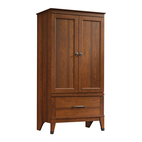
Linen Tower
Peppercorn Collection
ASSEMBLY TOOLS REQUIRED
Hammer
No. 2 Phillips Screwdriver
Tip Shown Actual Size
ADULT ASSEMBLY REQUIRED
TABLE OF CONTENTS
Part Identification...................2-3
Hardware Identification .............4
Assembly Steps....................5-18
Français..............................19-21
Espanol...............................22-24
Safety .................................25-26
Warranty...................................27
A UPPER RIGHT END 1
B UPPER LEFT END 1
C LOWER RIGHT END 1
D LOWER LEFT END 1
E UPPER TOP 1
F LOWER TOP 1
G BOTTOM 1
J UPPER ADJUSTABLE SHELF 2
K SMALL BACK 1
L LARGE BACK 1
M DOOR 1
N ADJUSTABLE SHELF 1
O LEG 2
P SKIRT 2
PART IDENTIFICATION: While not all parts are labeled, some of the parts will have a label or an inked
letter on the edge to help distinguish similar parts from each other. Use this PART IDENTIFICATION to help
identify similar parts.
Page 2 www.sauder.com/services 414817
PART IDENTIFICATION:
Page 3
www.sauder.com/services414817
A
BC
D
E
F
G
J
K
L
M
N
O
P
P
O
J
HARDWARE IDENTIFICATION
Screws are shown actual size. You may receive extra hardware with your unit.
Page 4 www.sauder.com/services 414817
14H HINGE - 2
RUBBER SLEEVE - 12
2R
DOOR STOP - 1
4I
SCREW COVER - 8
20P
BLACK 1/2" FLAT HEAD SCREW - 4
11S
ANGLE BRACKET - 4
5G
BLACK 9/16" LARGE HEAD SCREW - 9
1S
HIDDEN CAM - 10
1F CAM SCREW - 10
8F
METAL PIN - 12
1R
TACK GLIDE - 4
12E
NAIL - 43
1N
BLACK 1-7/8" FLAT HEAD SCREW - 13
2S
SAFETY BRACKET - 1
1G
CAM COVER - 10
12P
BLACK 7/8" MACHINE SCREW - 1
37S
HOLE PLUG - 16
11P
KNOB - 1
42K
Look for this icon. It means a video
assembly tip is available at:
www.sauder.com/services/tips
1
1
S
t
e
p
Page 5
www.sauder.com/services414817
Assemble your unit on a carpeted floor or on the empty carton to avoid scratching your unit or the floor.
Turn ten CAM SCREWS (8F) into the LOWER TOP (F) and LEGS (O).
Push ten HIDDEN CAMS (1F) into the LOWER ENDS (C and D).
8F
Do not tighten the HIDDEN CAMS in this step.
Arrow
1F
C
D
O
O
F
Arrow
1F
Arrow
1F
8F
Scan this QR code or go to this address:
http://qr.sauder.com/?ID=1236
to watch a video on how to assemble your unit.
2
2
S
t
e
p
Page 6 www.sauder.com/services 414817
Fasten the LEGS (O) to the LOWER ENDS (C and D). Tighten six HIDDEN CAMS.
O
O
Surface with
HIDDEN CAMS Surface with
HIDDEN CAMS
C
D
Curved edge
Curved edge
These surfaces
should be even.
These surfaces
should be even.
O
C
3
3
S
t
e
p
Page 7
www.sauder.com/services414817
Fasten the UPPER TOP (E) to the UPPER ENDS (A and B). Use four BLACK 1-7/8" FLAT HEAD SCREWS (2S).
E
A
B
Finished edge
Rounded edge
Surface with
more holes
Surface with holes
Surface without holes
BLACK 1-7/8" FLAT HEAD SCREW
(4 used in this step)
2S
4
4
S
t
e
p
Page 8 www.sauder.com/services 414817
Fasten the LOWER TOP (F) to the ENDS (A and B). Use four BLACK 1-7/8" FLAT HEAD SCREWS (2S).
BLACK 1-7/8" FLAT HEAD SCREW
(4 used in this step)
2S
A
B
F
Surface with
CAM SCREWS
Rounded edge
5
5
S
t
e
p
Page 9
www.sauder.com/services414817
Fasten the LOWER ENDS (C and D) to the LOWER TOP (F). Tighten four HIDDEN CAMS.
F
C
D
Surface with
HIDDEN CAMS
Surface without
HIDDEN CAMS
O
O
6
6
S
t
e
p
Page 10 www.sauder.com/services 414817
Fasten the BOTTOM (G) to the LOWER ENDS (C and D). Use four BLACK 1-7/8" FLAT HEAD SCREWS (2S).
BLACK 1-7/8" FLAT HEAD SCREW
(4 used in this step)
2S
C
D
G
Finished edge
If the BOTTOM (G) has
an unfinished surface, it
should be positioned here.
7
7
S
t
e
p
Page 11
www.sauder.com/services414817
Fasten four ANGLE BRACKETS (5G) to the TOPS (E and F). Use four BLACK 9/16" LARGE HEAD SCREWS (1S).
Fasten the SKIRTS (P) to the TOPS (E and F). Use four BLACK 9/16" LARGE HEAD SCREWS (1S) through theANGLE
BRACKETS on the TOPS and into the SKIRTS (P).
NOTE: There are no pre-drilled holes in the SKIRTS. The SCREWS will tighten into the grooves.
BLACK 9/16" LARGE HEAD SCREW
(8 used for the BRACKETS)
1S
E
F
Groove
5G
5G
P
P
8
8
S
t
e
p
Page 12 www.sauder.com/services 414817
Carefully turn your unit over onto its front edges and lay the LARGE BACK (L) over your unit.
Make equal margins along all four edges of the LARGE BACK (L). Push on opposite corners of your unit if needed to make it
“square”.
Fasten the LARGE BACK (L) to your unit using the NAILS (1N).
NOTE: You will not fasten NAILS into the bottom row of holes in the LARGE BACK (L) until you fasten the SMALL BACK (K).
Next, fasten the SMALL BACK (K) to your unit using the NAILS. The SMALL BACK (K) will overlap the LARGE BACK (L).
When fastening the SMALL BACK, line up the top set of holes in the SMALL BACK with the bottom set of holes in the LARGE
BACK first.
With your hammer, gently tap four TACK GLIDES (12E) into the bottom edges of the LOWER ENDS (C and D) and LEGS (O).
Do not stand the unit upright without the
BACK fastened. The unit may collapse.
Caution
NAIL
(43 used in this step)
1N
C
D
O
O
K
L
Unfinished
surface
Unfinished
surface
12E
Do not tap NAILS into the bottom
row of the LARGE BACK (L) until
you fasten the SMALL BACK (K).
When fastening SMALL BACK (K),
start with the top row of holes first. Line
up the holes in the SMALL BACK (K)
with the holes in the LARGE BACK (L).
9
9
S
t
e
p
Page 13
www.sauder.com/services414817
Carefully stand your unit upright.
Push the RUBBER SLEEVES (2R) over the METAL PINS (1R).
Insert twelve METAL PINS into the hole locations of your choice in the lower and upper sets of holes in the UPPER ENDS (A and B)
and LOWER ENDS (C and D). Set the UPPER ADJUSTABLE SHELVES (J) and ADJUSTABLE SHELF (N) onto the METAL PINS.
(12 used)
D
C
N
J
B
1R
2R
A
10
10
S
t
e
p
Page 14 www.sauder.com/services 414817
Fasten the HINGES (14H) to the DOOR (M). Use four BLACK 1/2" FLAT HEAD SCREWS (11S).
BLACK 1/2" FLAT HEAD SCREW
(4 used in this step)
11S
14H
M
11
11
S
t
e
p
Page 15
www.sauder.com/services414817
Fasten the DOOR (M) to the LOWER RIGHT END (C). Use the screws in the HINGES.
NOTE: You may need to loosen the mounting screw to slide the HINGE slightly out of the slot. Retighten the screw before mounting
the HINGE to the END.
Fasten a KNOB (42K) to the DOOR (M). Use a BLACK 7/8" MACHINE SCREW (37S).
Push the DOOR STOP (4I) into the hole in the LOWER LEFT END (D).
Mounting screw (depth)
4I
42K
D
C
BLACK 7/8" MACHINE SCREW
(1 used for the KNOB)
37S
M
12
12
S
t
e
p
Page 16 www.sauder.com/services 414817
Mounting screw (depth)
(vertical adjustment)
Adjusting screw (horizontal)
Refer to the enlarged diagram to identify the parts on the HINGES.
The DOORS may need some adjustments. Follow the text below to make needed adjustments.
DOOR ADJUSTMENTS:
To adjust the DOORS from side to side (horizontal), loosen the mounting screw several turns, then turn the adjusting screw in or out.
Tighten the mounting screw after making adjustments.
To adjust the DOORS up and down (vertical), loosen both vertical adjustment screws. Move the DOORS up or down to the desired
location. Tighten the screws after making adjustments.
To adjust the DOORS in or out (depth), loosen the mounting screw one turn and move the DOORS in or out, as needed. Tighten the
mounting screw after making adjustments.
13
13
S
t
e
p
Page 17
www.sauder.com/services414817
IMPORTANT: This unit must be fastened to a wall.
Fasten the SAFETY BRACKET (1G) to your unit for added stability. Use a BLACK 9/16” LARGE HEAD SCREW (1S) into the top
of the unit and a BLACK 1-7/8” FLAT HEAD SCREW (2S) into a stud in your wall.
BLACK 1-7/8” FLAT HEAD SCREW
(1 used into a stud in your wall)
2S
BLACK 9/16” LARGE HEAD SCREW
(1 used into the top of your unit)
1S
1G
14
14
S
t
e
p
Page 18 www.sauder.com/services 414817
Center a SCREW COVER (20P) over the head of each visible SCREW and press firmly.
Push a CAM COVER (12P) onto each visible HIDDEN CAM.
Insert the HOLE PLUGS (11P) into the holes in the UPPER ENDS (A and B).
NOTE: Please read the back pages of the instruction booklet for important safety information.
This completes assembly. To clean your unit, dampen a cloth with tap water and wipe.
To cover HIDDEN CAMS
(10 used)
12P
To cover screws
(8 used) 20P
20 lbs.
25 lbs.
40 lbs.
25 lbs.
25 lbs.
25 lbs.
11P
(16 used)
B
A
A l’usage exclusif du
Canada Noter la date
d’achat de cet élément
et conserver le livret
pour future référence.
Pour contacter Sauder
en ce qui concerne cet
élément, faire référence
au numéro de lot et
numéro de modèle en
appelant notre numéro
sans frais.
Lot nº : ____________
Date de
l’achat: ____________
LISTE DE PIÈCES
REFERENCE DESCRIPTION QUANTITÉ
LISTE DE PIÈCES
REFERENCE DESCRIPTION QUANTITÉ
NOUS SOMMES LA POUR VOUS AIDER!
Nous faisons de notre mieux pour nous assurer que
votre meuble arrive dans d’excellentes conditions. Nos
représentants du service Clientèle sont aimables et prêts
à vous aider au cas où une pièce aurait été endommagée
ou manquerait (ou si vous aviez besoin d’aide pour
l’assemblage). NE RAMENEZ PAS LE MEUBLE AU
MAGASIN. Au Canada, composez ce numéro d’appel gratuit:
1-800-523-3987
Du lundi au vendredi, de 9 heures du matin à
5:30 heures du soir (horaire Côte Est)
(sauf jours fériés)
Si une pièce a besoin d’être remplacée, la pièce de
remplacement sera envoyée dans les 48 heures. (Sauf
week-ends et jours fériés)
Utilisez les instructions d’assemblage en français avec
les schémas étape par étape du manuel d’instruction
en anglais. Chaque étape en français correspond à la
même étape en anglais. La pièce devant être attachée
à l’élément est représentée en gris sur les schémas de
chaque étape pour plus de précision. Comparer la “Liste
de pièces” ci-dessous avec la “PART IDENTIFICATION”
du manuel en anglais pour vous familiariser avec les
pièces avant l’assemblage.
REMARQUE : CE MANUEL D’INSTRUCTIONS
CONTIENT D’IMPORTANTES INFORMATIONS
RELATIVES À LA SÉCURITÉ. À LIRE ET CONSERVER
POUR TOUTE RÉFÉRENCE FUTURE.
12E PATIN...............................................4
1F
EXCENTRIQUE ESCAMOTABLE
....10
8F VIS D'EXCENTRIQUE...................10
1G CONSOLE DE SÉCURITÉ ..............1
5G CONSOLE À ÉQUERRE.................4
14H CHARNIÈRE....................................2
4I ARRÊT DE PORTE..........................1
42K BOUTON..........................................1
1N CLOU.............................................43
20P CACHE-VIS .....................................8
11P BOUCHON.....................................16
12P
COUVERCLE D'EXCENTRIQUE
.....10
1R GOUPILLE EN MÉTAL ..................12
2R MANCHON EN CAOUTCHOUC....12
1S VIS TÊTE LARGE 14 mm NOIRE....9
2S VIS TÊTE PLATE 48 mm NOIRE...13
11S VIS TÊTE PLATE 13 mm NOIRE.....4
37S VIS À MÉTAUX 22 mm NOIRE........1
A EXTRÉMITÉ DROITE
SUPÉRIEURE..................................1
B EXTRÉMITÉ GAUCHE
SUPÉRIEURE..................................1
C EXTRÉMITÉ DROITE
INFÉRIEURE ...................................1
D EXTRÉMITÉ GAUCHE
INFÉRIEURE ...................................1
E DESSUS SUPÉRIEUR....................1
F DESSUS INFÉRIEUR......................1
G DESSOUS .......................................1
J TABLETTE RÉGLABLE
SUPÉRIEURE..................................2
K PETITARRIÈRE..............................1
L GRAND ARRIÈRE ...........................1
M PORTE.............................................1
N TABLETTE RÉGLABLE...................1
O PIED.................................................2
P PLINTHE..........................................2
Chiffonnier414817
Page 19
www.sauder.com/services414817
ÉTAPE 9
Relever, avec précaution, l'élément dans sa position
verticale.
Enfoncer les MANCHONS EN CAOUTCHOUC (2R) sur
les GOUPILLES EN MÉTAL (1R).
Insérer douze GOUPILLES EN MÉTAL dans les
trous choisis le jeu inférieur et supérieur de trous
les EXTRÉMITÉS SUPÉRIEURES (A et B) et les
EXTRÉMITÉS INFÉRIEURES (C et D). Poser les
TABLETTES RÉGLABLES SUPÉRIEURES (J) et la
TABLETTE RÉGLABLE (N) sur les GOUPILLES
EN MÉTAL.
ÉTAPE 8
Attention
Ne pas relever l'élément dans sa position verticale avant
d'avoir fixé l’ARRIÈRE. L'élément risque de s'effondrer.
Avec précaution, retourner l'élément sur ses chants
avant et placer le GRAND ARRIÈRE (L) sur l'élément.
Veiller à avoir des marges égales le long des quatre
chants de le GRAND ARRIÈRE (L). Si besoin est,
enfoncer sur les coins opposés de l'élément pour
s'assurer d'être « d'équerre ».
Fixer le GRAND ARRIÈRE (L) à l'élément à l'aide des
CLOUS (1N).
REMARQUE : Ne pas fixer les CLOUS dans la rangée
inférieure des trous dans le GRAND ARRIÈRE (L) avant
de fixer le PETITARRIÈRE (K).
Ensuite, fixer le PETITARRIÈRE (K) à l'élément à l'aide
des CLOUS. Le PETITARRIÈRE va chevaucher le
GRAND ARRIÈRE (L).
Pour fixer le PETITARRIÈRE, aligner le jeu supérieur
de trous de le PETITARRIÈRE avec le jeu inférieur de
trous de le GRAND ARRIÈRE en premier.
À l'aide d'un marteau, enfoncer quatre PATINS (12E) dans
les chants inférieurs des EXTRÉMITÉS INFÉRIEURES (C
et D) et les PIEDS (O).
ÉTAPE 7
Fixer quatre CONSOLES À ÉQUERRE (5G) aux
DESSUS (E et F). Utiliser quatre VIS TÊTE LARGE
14 mm NOIRES (1S).
Fixer les PLINTHES (P) aux DESSUS (E et F). Utiliser
quatre VIS TÊTE LARGE 14 mm NOIRES (1S) à travers
les CONSOLES À ÉQUERRE situées sur les DESSUS,
et dans les PLINTHES (P).
REMARQUE : Les PLINTHES ne comportent pas de
trous pré-percés. Serrer les VIS dans les rainures.
ÉTAPE 6
Fixer le DESSOUS (G) aux EXTRÉMITÉS
INFÉRIEURES (C et D). Utiliser quatre VIS TÊTE
PLATE 48 mm NOIRES (2S).
ÉTAPE 5
Fixer les EXTRÉMITÉS INFÉRIEURES (C et D) au
DESSUS INFÉRIEUR (F). Serrer quatre EXCENTRIQUES
ESCAMOTABLES.
ÉTAPE 4
Fixer le DESSUS INFÉRIEUR (F) aux EXTRÉMITÉS (A et B).
Utiliser quatre VIS TÊTE PLATE 48 mm NOIRES (2S).
ÉTAPE 3
Fixer le DESSUS SUPÉRIEUR (E) aux EXTRÉMITÉS
SUPÉRIEURES (A et B). Utiliser quatre VIS TÊTE
PLATE 48 mm NOIRES (2S).
ÉTAPE 2
Fixer les PIEDS (O) aux EXTRÉMITÉS INFÉRIEURES (C
et D). Serrer six EXCENTRIQUES ESCAMOTABLES.
ÉTAPE 1
Repérer cette icône. Elle signifie qu'un conseil de
montage vidéo est disponible à :www.sauder.com/
services/tips
Ne pas serrer les CAMES ESCAMOTABLES dans cette étape.
Assembler l'élément sur un sol à moquette ou sur le
carton vide pour éviter d'endommager l'élément ou le sol.
Faire tourner dix VIS D'EXCENTRIQUE (8F) dans le
DESSUS INFÉRIEUR (F) et les PIEDS (O).
Enfoncer dix EXCENTRIQUES ESCAMOTABLES (1F)
dans les EXTRÉMITÉS INFÉRIEURES (C et D).
Page 20 www.sauder.com/services 414817

Other Sauder Indoor Furnishing manuals

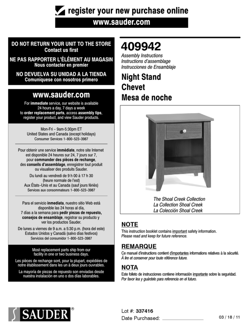
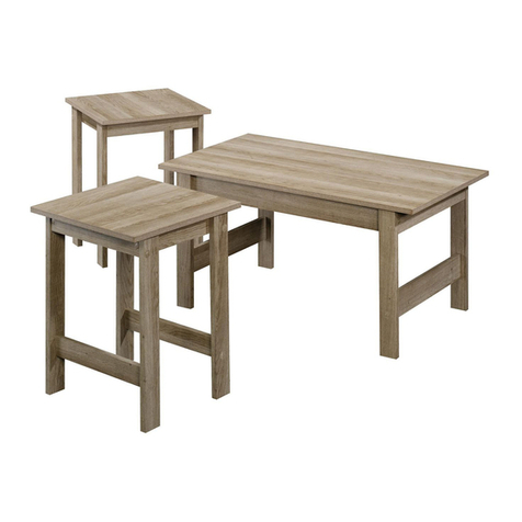
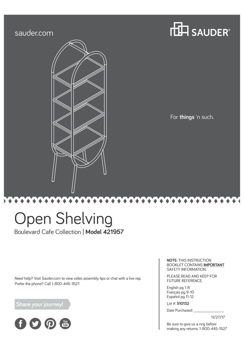
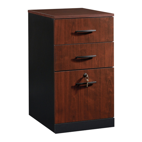
Sauder Registry Row Series User manual

Sauder

Sauder Registry Row Series User manual

Sauder Steel River 423976 User manual

Sauder

Sauder Steel River 423976 User manual

Sauder Harbor View 403793 User manual

Sauder

Sauder Harbor View 403793 User manual

Sauder Bandit 425667 User manual

Sauder

Sauder Bandit 425667 User manual

Sauder Shoal Creek 412093 User manual

Sauder

Sauder Shoal Creek 412093 User manual

Sauder Moderna 5427968 User manual

Sauder

Sauder Moderna 5427968 User manual

Sauder 424273 User manual

Sauder

Sauder 424273 User manual

Sauder 410375 User manual

Sauder

Sauder 410375 User manual

Sauder Boulevard Cafe 422356 User manual

Sauder

Sauder Boulevard Cafe 422356 User manual

Sauder 413072 User manual

Sauder

Sauder 413072 User manual

Sauder 426932 User manual

Sauder

Sauder 426932 User manual

Sauder Boone Mountain 416598 User manual

Sauder

Sauder Boone Mountain 416598 User manual

Sauder 419321 User manual

Sauder

Sauder 419321 User manual

Sauder 430628 User manual

Sauder

Sauder 430628 User manual

Sauder County Line 417771 User manual

Sauder

Sauder County Line 417771 User manual

Sauder Costa Credenza 422984 User manual

Sauder

Sauder Costa Credenza 422984 User manual

Sauder Shoal Creek 411201 User manual

Sauder

Sauder Shoal Creek 411201 User manual

Sauder DESIGNER'S IMAGE 430621 User manual

Sauder

Sauder DESIGNER'S IMAGE 430621 User manual

Sauder Jaclyn Smith 416404 User manual

Sauder

Sauder Jaclyn Smith 416404 User manual

Sauder 420545 User manual

Sauder

Sauder 420545 User manual

Sauder Transit 414417 User manual

Sauder

Sauder Transit 414417 User manual

Sauder Harbor View 400742 User manual

Sauder

Sauder Harbor View 400742 User manual

Sauder Via 419612 User manual

Sauder

Sauder Via 419612 User manual

Sauder Storage Cabinet 419496 User manual

Sauder

Sauder Storage Cabinet 419496 User manual

Popular Indoor Furnishing manuals by other brands

Seating Matters BARIATRIC SORRENTO instruction manual

Seating Matters

Seating Matters BARIATRIC SORRENTO instruction manual

Sunjoy L-BR098PST-A Assembly instructions

Sunjoy

Sunjoy L-BR098PST-A Assembly instructions

Belnick SB-1960-CH-CREAM-GG Assembly instructions

Belnick

Belnick SB-1960-CH-CREAM-GG Assembly instructions

Rapidline GTDSHELF Assembly instructions

Rapidline

Rapidline GTDSHELF Assembly instructions

PHI VILLA THD5-0605-102 Use and care guide

PHI VILLA

PHI VILLA THD5-0605-102 Use and care guide

convenience concepts LAREDO 413199 Assembly instructions

convenience concepts

convenience concepts LAREDO 413199 Assembly instructions

Bensons for Beds HIP HOP STK268006 Assembly instructions

Bensons for Beds

Bensons for Beds HIP HOP STK268006 Assembly instructions

Mocka Mischa Assembly instructions

Mocka

Mocka Mischa Assembly instructions

Euro-Rite Cabinets Standard Wall Cabinet Assembly instructions

Euro-Rite Cabinets

Euro-Rite Cabinets Standard Wall Cabinet Assembly instructions

Newpo GLWB123 Guide to Assembly & Usage

Newpo

Newpo GLWB123 Guide to Assembly & Usage

Woodstock Shop FoxD3640 instruction sheet

Woodstock

Woodstock Shop FoxD3640 instruction sheet

Crate&Barrel Caicos quick start guide

Crate&Barrel

Crate&Barrel Caicos quick start guide

EAST COAST Rocking Assembly guide

EAST COAST

EAST COAST Rocking Assembly guide

Atlantic Oskar 160 DVD Assembly guide

Atlantic

Atlantic Oskar 160 DVD Assembly guide

Carolina Outdoors CO7825-BLK Assembly instructions

Carolina Outdoors

Carolina Outdoors CO7825-BLK Assembly instructions

Next 140392 Assembly instruction

Next

Next 140392 Assembly instruction

ANREX TAURUS 1DGL Z Instructions for assembling and operating

ANREX

ANREX TAURUS 1DGL Z Instructions for assembling and operating

Tuohy Tryg installation guide

Tuohy

Tuohy Tryg installation guide

manuals.online logo
manuals.online logoBrands
  • About & Mission
  • Contact us
  • Privacy Policy
  • Terms and Conditions

Copyright 2025 Manuals.Online. All Rights Reserved.