manuals.online logo
Brands
  1. Home
  2. •
  3. Brands
  4. •
  5. Sauder
  6. •
  7. Indoor Furnishing
  8. •
  9. Sauder Shoal Creek 410287 User manual

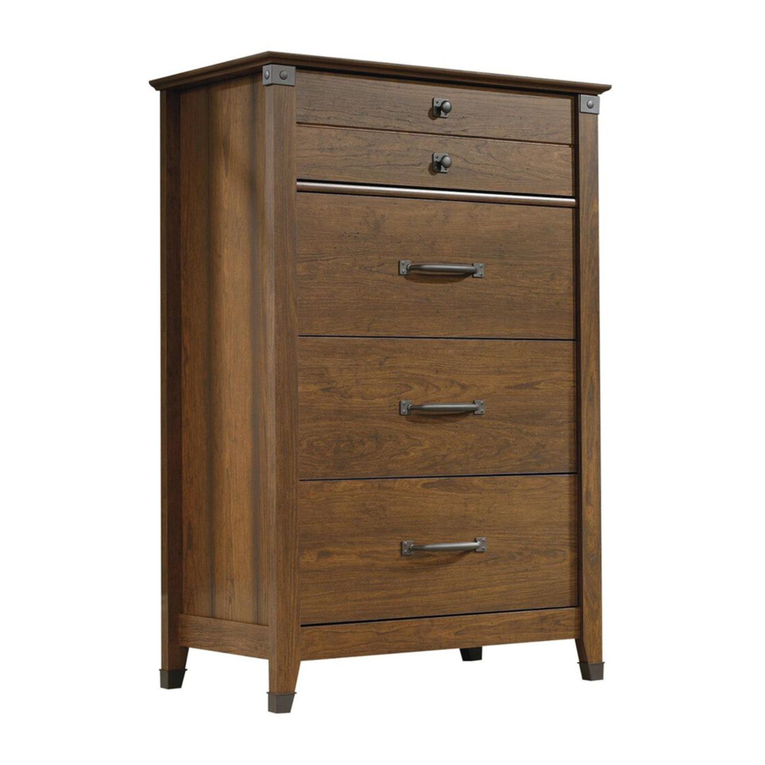
Sauder Shoal Creek 410287 User manual

NOTE: THIS INSTRUCTION
BOOKLET CONTAINS IMPORTANT
SAFETY INFORMATION.
PLEASE READ AND KEEP FOR
FUTURE REFERENCE.
Enlish p 1-22
Français p 23-25
Español p 26-28
Lot # 397211 10/12/16
Purchased: __________________
Be sure to ive us a rin before
makin any returns. 1-800-523-3987
Dresser
Shoal Creek Collection | Model 410287
Need help? Visit Sauder.com to view video assembly tips or chat with a live rep.
Prefer the phone? Call 1-800-523-3987.
Share your journey!
sauder.com
WARNING
CHOKING HAZARD - Small Parts
Not for children under 3 years.
Adult assembly required.
Table of Contents Assembly Tools Required
2-3
4-5
6-22
23-25
26-28
29-30
31
Part Identification
Hardware Identification
Assembly Steps
Français
Español
Safety
Warranty
Hammer
Not actual size
No. 2 Phillips Screwdriver
Tip Shown Actual Size
Skip the power trip.
This time.
410287 www.sauder.com/servicesPae 2
Part Identification
åWhile not all parts are labeled, some of the parts will have a label or an inked letter on the ede
to help distinuish similar parts from each other. Use this part identification to help identify similar parts.
A RIGHT END (1)
B LEFT END (1)
C UPRIGHT (1)
D TOP (1)
D10 SMALL RIGHT DRAWER SIDE (2)
D11 SMALL LEFT DRAWER SIDE (2)
D132 RIGHT DRAWER SIDE (4)
D138 LEFT DRAWER SIDE (4)
D166 SMALL DRAWER BACK (2)
D167 DRAWER BACK (4)
D975 DRAWER BOTTOM (6)
E BOTTOM (2)
F BACK (1)
G RIGHT FRONT LEG (1)
H LEFT FRONT LEG (1)
I REAR LEG (2)
J END MOLDING (2)
K2 SMALL RIGHT DRAWER FRONT (1)
L2 SMALL LEFT DRAWER FRONT (1)
M65 DRAWER BRACE (6)
Q2 RIGHT DRAWER FRONT (2)
R2 LEFT DRAWER FRONT (2)
SS BRACE (1)
Part Identification Now you know
our ABCs.
410287www.sauder.com/services Pae 3
A
B
C
D
E
F
G
H
I
J
K2
L2
D166 D10
D11
D975
Q2
R2
D167 D132
D138
E
I
SS
D975
D975
D975
D166 D10
D11
D167 D132
D138
J
M65
M65
M65
M65
Hardware Identification
åScrews are shown actual size. You may receive extra hardware with your unit.
40CA CABINET RIGHT - 6 40CB CABINET LEFT - 6 40CC DRAWER RIGHT - 6 40CD DRAWER LEFT - 6
PULL- 8
EE FF KNOB- 4 METAL PIN - 4
GG
HH SLIDE CAM - 12 FOOT - 1
TT FOOT BASE - 1
UU
SAFETY BRACKET - 1
WW
HIDDEN CAM - 22
AA2 CAM SCREW - 12
BB2 CAM DOWEL - 10
CC2
410287 www.sauder.com/servicesPae 4
11L WARNING LABEL - 1
(Refer to Step 15 for proper location and application)
WARNING AVERTISSEMENT ADVERTENCIA
Serious or fatal crushing injuries can
occur from furniture tipover.
To help prevent tipover:
• Install tipover restraint provided.
• Place heaviest items in the lower drawers.
• Unless specifically desined to
accommodate, do not set TVs or other
heavy objects on top of this product.
• Never allow children to climb or han on
drawers, doors, or shelves.
• Never open more than one drawer at a time.
(OR)
• Do not defeat or remove the drawer
interlock system.
Use of tipover restraints may only reduce,
but not eliminate, the risk of tipover.
This is a permanent label. Do not remove.
Des blessures graves ou fatales par écrasement
peuvent survenir si le mobilier bascule. Pour
prévenir le basculement:
• Installer le dispositif anti-basculement fourni.
• Placer les articles plus lourds dans les tiroirs inférieurs.
• Sauf si le meuble a été conçu spécialement à
cette fin, ne pas mettre de téléviseur ou d’autre
objets lourds sur le dessus de ce meuble.
• Ne jamais laisser d’enfants rimper sur les
tiroirs, les portes ou les étaères ou s’y aripper.
• Ne jamais ouvrir plus d’un tiroir à la fois.
(OU)
• Ne pas démanteler ou enlever le système de
verrouillae pour tiroir.
L’utilisation de dispositifs anti-basculement peut
réduire le risque de basculement, mais pas l’éliminer.
Cette étiquette est permanente. Ne pas l’enlever.
Lesiones graves o fatales por aplastamiento, pueden
ocurrir por el volcar de los muebles. Para ayudar a
prevenir que se volqué:
• Instalar la contención brindada para evitar que se volqué.
• Coloque los artículos más pesados en los cajones
inferiores.
• A menos que sea específicamente diseñado para
acomodar, no establezca televisores u otros objetos
pesados en la parte superior de este producto.
• Nunca permita que los niños se suban o se cueluen
de cajones, puertas o estantes.
• Nunca abra más de un cajón a la vez.
(O)
• No anule o elimine el sistema de bloqueo de los cajones.
El uso de la contención puede solamente reducir, pero
no eliminar, el riesgo de volcar.
Esta es una etiqueta permanente. No remover.
10/16 395783
Hardware Identification
åScrews are shown actual size. You may receive extra hardware with your unit.
410287www.sauder.com/services Pae 5
BLACK 2-1/4" FLAT HEAD SCREW - 6
KK BLACK 1-7/8" FLAT HEAD SCREW - 3
LL
BLACK 1-1/8" MACHINE SCREW - 4
MM SILVER 3/4" MACHINE SCREW - 16
NN
BLACK 9/16" FLAT HEAD SCREW - 4
OO QQ GOLD 5/16" FLAT HEAD SCREW - 48
NAIL - 47
RR BLACK 1-1/4" FLAT HEAD SCREW - 4
VV
BLACK 9/16" LARGE HEAD SCREW - 1
XX 30S BLACK 1-9/16" FLAT HEAD SCREW - 30
Step 1 Look for this icon. It means a
video assembly tip is available at
www.sauder.com/services/tips
å Assemble your unit on a carpeted floor or on the empty
carton to avoid scratchin your unit or the floor.
å Push twenty-two HIDDEN CAMS (AA2) into the
ENDS (A and B), UPRIGHT (C), BOTTOMS (E), and
DRAWER BRACES (M65). Then, insert the metal end of
ten CAM DOWELS (CC2) into the HIDDEN CAMS.
410287 www.sauder.com/servicesPae 6
A
B
C
E
E
Arrow
Insert the metal end of the CAM
DOWEL into the HIDDEN CAM.
Arrow
Do not tihten the HIDDEN CAMS in this step.
Do not insert CAM DOWELS into these edes.
Arrow
The arrow in the HIDDEN
CAM must point toward the
hole in the ede of the board.
Hole
(22 used)
Do not insert
CAM DOWELS
into these parts.
Arrow
(10 used)
AA2
CC2
AA2
M65
M65
M65
M65
M65
M65
Scan this QR code or go to this address:
http://qr.sauder.com/?ID=1612
to watch a video on how to assemble your unit.
å Turn twelve CAM SCREWS (BB2) into the FRONT LEGS (G and H)
and DRAWER FRONTS (K2, L2, Q2, and R2).
Step 2
410287www.sauder.com/services Pae 7
G
H
K2
L2
Q2
Q2
R2
R2
BB2
(12 used)
Step 3
å Fasten the REAR LEGS (I) to the ENDS (A and B). Use six
BLACK 2-1/4" FLAT HEAD SCREWS (KK).
410287 www.sauder.com/servicesPae 8
A
B
I
I
Surface without
HIDDEN CAMS Surface without
HIDDEN CAMS
These holes
must be here.
Anled ede
These holes
must be here.
BLACK 2-1/4" FLAT HEAD SCREW
(6 used in this step)
KK
Remember:
Rihty tihty.
Lefty loosey.
å Turn four BLACK 9/16" FLAT HEAD SCREWS (OO) into
the ENDS (A and B) until the shoulders of the SCREWS
rest on the surfaces of the ENDS.
å Slide the END MOLDINGS (J) onto the ENDS (A and B).
Line up the rooves in the MOLDINGS over the heads of
the SCREWS in the ENDS.
Step 4
410287www.sauder.com/services Pae 9
A
B
J
J
BLACK 9/16" FLAT HEAD SCREW
(4 used in this step)
OO
Shoulder
Surface without
HIDDEN CAMS Surface without
HIDDEN CAMS
Apply pressure with your hands
as you uide the MOLDINGS over
the SCREWS and onto the ENDS.
Step 5
å Fasten the FRONT LEGS (G and H) to the ENDS (A and B).
Tihten six HIDDEN CAMS.
410287 www.sauder.com/servicesPae 10
A
G
B
H
1
2
Surface with
HIDDEN CAMS
Surface with
HIDDEN CAMS
Anled ede
å Fasten three CABINET RIGHTS (40CA) to the RIGHT END (A)
and three CABINET LEFTS (40CB) to the LEFT END (B). Use
twelve GOLD 5/16" FLAT HEAD SCREWS (QQ) throuh
holes #1 and #4.
Step 6
410287www.sauder.com/services Pae 11
A
G
B
H
1
2
3
4
1
2
34
1
2
3
41
2
3
4
1
2
34
1
2
3
4
Roller end
Roller end
GOLD 5/16" FLAT HEAD SCREW
(12 used in this step)
QQ
Step 7
å Fasten three CABINET RIGHTS (40CA) and three
CABINET LEFTS (40CB) to the UPRIGHT (C). Use
twelve GOLD 5/16" FLAT HEAD SCREWS (QQ)
throuh holes #1 and #4.
410287 www.sauder.com/servicesPae 12
C
Surface with
HIDDEN CAMS
1
2
3
41
2
3
41
2
3
4
1
2
3
4
3
4
3
4
Roller end
GOLD 5/16" FLAT HEAD SCREW
(12 used in this step)
QQ
Unfinished ede
å Fasten the LEFT END (B) and UPRIGHT (C) to the
TOP (D). Tihten four HIDDEN CAMS.
Step 8
410287www.sauder.com/services Pae 13
Start Tighten
Arrow
Minimum
190 derees
Caution
Risk of damae or
injury. HIDDEN CAMS
must be completely
tihtened. HIDDEN
CAMS that are not
completely tihtened
may loosen, and parts
may separate. To
completely tihten:
Arrow
Maximum
210 derees
B
C
D
H
Surface
with
HIDDEN
CAMS
Surface
without
HIDDEN
CAMS
Finished ede
Surface with holes
Do not stand the unit upriht without the
BACK fastened. The unit may collapse.
Caution
Step 9
å Insert four METAL PINS (GG) into the BOTTOMS (E).
å Insert the METAL PINS (GG) in one end of the
BOTTOMS (E) into the holes in the LEFT END (B).
å Fasten the BOTTOMS (E) to the LEFT END (B). Tihten
two HIDDEN CAMS.
å Fasten the BOTTOMS (E) to the UPRIGHT (C). Use two
BLACK 1-7/8" FLAT HEAD SCREWS (LL).
410287 www.sauder.com/servicesPae 14
B
C
GG
E
E
BLACK 1-7/8" FLAT HEAD SCREW
(2 used in this step)
LL
Finished ede
Finished ede
Surface with HIDDEN CAMS
Arrow
Minimum
190 derees
Maximum
210 derees
(4 used)
Now miht be a
ood time to refresh
your drink.
å Fasten the RIGHT END (A) to the TOP (D) and BOTTOMS (E). Tihten
four HIDDEN CAMS.
å NOTE: Be sure the METAL PINS in the BOTTOMS insert into the holes
in the RIGHT END.
å Fasten the BRACE (SS) and FOOT BASE (UU) to the BOTTOM (E).
Use four BLACK 1-1/4" FLAT HEADSCREWS (VV) throuh the BASE,
throuh the BRACE, and into the BOTTOM. Then, push the FOOT (TT)
into the FOOT BASE (UU).
å NOTE: Turn the screw end of the FOOT completely in. Adjustments
will be made to the FOOT after the unit is standin upriht.
Step 10
410287www.sauder.com/services Pae 15
A
D
G
TT
UU
SS
E
E
Arrow
Minimum
190 derees
Maximum
210 derees
BLACK 1-1/4" FLAT HEAD SCREW
(4 used in this step)
VV
Turn completely in.
Step 11
å Carefully turn your unit over onto its front edes. Unfold the
BACK (F) and lay it over your unit.
å Make equal marins alon all four edes of the BACK (F).
Push on opposite corners of your unit if needed to make
it "square".
å Fasten the BACK (F) to your unit usin the NAILS (RR).
å NOTE: Be sure to tap NAILS into the holes that line up over
the UPRIGHT (C).
410287 www.sauder.com/servicesPae 16
F
NAIL
(47 used in this step)
RR
These holes must line up
over the UPRIGHT (C).
Cut-outs to attach a mirror
Printed information
must be facin up.
Do not stand the unit upriht without the
BACK fastened. The unit may collapse.
Caution
Step 12
410287www.sauder.com/services Pae 17
VIEW THE T-LOCK BOX VIDEO
å Insert the DRAWER SIDES (D132 and D138) at
an angle into the slot at each end of the RIGHT
DRAWER FRONT (Q2).
å Slide the DRAWER BOTTOM (D975) into the grooves
in the DRAWER SIDES (D132 and D138) and RIGHT
DRAWER FRONT (Q2).
å Fasten the DRAWER BRACE (M65) to the
DRAWER FRONT (Q2). Tighten one HIDDEN CAM.
å Fasten the DRAWER BACK (D167) to the DRAWER SIDES (D132
and D138) and DRAWER BRACE (M65). Use five BLACK 1-9/16"
FLAT HEAD SCREWS (30S). Repeat this step for the other DRAWERS
using the DRAWER FRONTS (Q2 and R2). Use the SMALL DRAWER
FRONTS (K2 and L2), SMALL DRAWER SIDES (D10 and D11), and
SMALL DRAWER BACKS (D166) for the small drawers.
12
34
Be sure the DRAWER
BOTTOM inserts into the
DRAWER FRONT roove.
Groove
Q2
Q2
D138
D975
D132
D132
D138
D167
Q2 D138
D132
M65
30S
Start each screw a few turns before
completely tihtenin any of them.
BLACK 1-9/16" FLAT HEAD SCREW
(30 used in this step)
1
2
Unfinished
surface
The tabs should insert freely
into the slots. Gently tilt the
DRAWER SIDES side to side
until the tabs slip into the slots.
With the palm of your hand,
tap the DRAWER BOTTOM
down into the roove.
M65
Surface with
HIDDEN CAM
Step 13
410287 www.sauder.com/servicesPae 18
Almost time to
celebrate! With a nap.
å Insert a SLIDE CAM (HH) into the SMALL DRAWER SIDES (D10 and D11).
å Fasten the DRAWER RIGHT (40CC) and DRAWER LEFT (40CD) to the
SMALL DRAWER SIDES (D10 and D11). Use four GOLD 5/16" FLAT
HEAD SCREWS (QQ) throuh holes #1 and #4.
å NOTE: The screw head in the CAM must be visible throuh the slotted
hole in the SLIDE.
å Repeat this step for the other drawers.
1
2
3
4
Roller end
Roller end
Screw head - turn CAM to line up holes in
the SLIDES with holes in DRAWER SIDES
HH
HH
1
2
3
4D138
D132
GOLD 5/16" FLAT HEAD SCREW
(24 used in this step)
QQ
(4 screws per drawer)
å Fasten two KNOBS (FF) to the SMALL RIGHT DRAWER
FRONT (K2). Use two BLACK 1-1/8" MACHINE SCREWS (MM).
å Fasten two PULLS (EE) to the RIGHT DRAWER FRONT (Q2).
Use four SILVER 3/4" MACHINE SCREWS (NN).
å Repeat this step for the other drawers.
Step 14
410287www.sauder.com/services Pae 19
K2
Q2
EE
FF
BLACK 1-1/8" MACHINE SCREW
(4 used in this step)
MM
SILVER 3/4" MACHINE SCREW
(16 used in this step)
NN
Want options? Customize
your item with add-on
hardware kits available
on sauder.com.
Step 15
å Carefully stand your unit upriht.
å Position your unit in its final location. Turn the FOOT down so it touches the floor.
å To insert the drawers into your unit, tip the front of the drawers down and drop the rollers on the drawers behind the rollers
on the unit. Lift the front of the drawers up and slide them into the unit.
å Apply the WARNING LABEL (11L) to the upper left DRAWER BOTTOM (D975). You should be able to read the label when
the drawer is open. When the drawer is closed, it will hide the label. Peel o the backin and apply the label as shown in
the diaram.
å NOTE: This is a permanent label intended to last for the life of the product. Once applied, do not try to remove it.
410287 www.sauder.com/servicesPae 20
Q2
Q2
R2
K2
L2
R2
Turn the ADJUSTABLE FOOT
downward until it touches the floor.
TT
Floor
IMPORTANT: The ADJUSTABLE FOOT should not
extend beyond the bottom edes of the LEGS.
WARNING AVERTISSEMENT ADVERTENCIA
Serious or fatal crushing injuries can
occur from furniture tipover.
To help prevent tipover:
• Install tipover restraint provided.
• Place heaviest items in the lower drawers.
• Unless specifically desined to
accommodate, do not set TVs or other
heavy objects on top of this product.
• Never allow children to climb or han on
drawers, doors, or shelves.
• Never open more than one drawer at a time.
(OR)
• Do not defeat or remove the drawer
interlock system.
Use of tipover restraints may only reduce,
but not eliminate, the risk of tipover.
This is a permanent label. Do not remove.
Des blessures graves ou fatales par écrasement
peuvent survenir si le mobilier bascule. Pour
prévenir le basculement:
• Installer le dispositif anti-basculement fourni.
• Placer les articles plus lourds dans les tiroirs inférieurs.
• Sauf si le meuble a été conçu spécialement à
cette fin, ne pas mettre de téléviseur ou d’autre
objets lourds sur le dessus de ce meuble.
• Ne jamais laisser d’enfants rimper sur les
tiroirs, les portes ou les étaères ou s’y aripper.
• Ne jamais ouvrir plus d’un tiroir à la fois.
(OU)
• Ne pas démanteler ou enlever le système de
verrouillae pour tiroir.
L’utilisation de dispositifs anti-basculement peut
réduire le risque de basculement, mais pas l’éliminer.
Cette étiquette est permanente. Ne pas l’enlever.
Lesiones graves o fatales por aplastamiento, pueden
ocurrir por el volcar de los muebles. Para ayudar a
prevenir que se volqué:
• Instalar la contención brindada para evitar que se volqué.
• Coloque los artículos más pesados en los cajones
inferiores.
• A menos que sea específicamente diseñado para
acomodar, no establezca televisores u otros objetos
pesados en la parte superior de este producto.
• Nunca permita que los niños se suban o se cueluen
de cajones, puertas o estantes.
• Nunca abra más de un cajón a la vez.
(O)
• No anule o elimine el sistema de bloqueo de los cajones.
El uso de la contención puede solamente reducir, pero
no eliminar, el riesgo de volcar.
Esta es una etiqueta permanente. No remover.
10/16 395783
11L
D975

Other Sauder Indoor Furnishing manuals
Sauder Cannery Bridge 424192 User manual

Sauder

Sauder Cannery Bridge 424192 User manual

Sauder Original Cottage 414183 User manual

Sauder

Sauder Original Cottage 414183 User manual

Sauder Corner Entertainment Credenza 403818 User manual

Sauder

Sauder Corner Entertainment Credenza 403818 User manual

Sauder Shoal Creek Series User manual

Sauder

Sauder Shoal Creek Series User manual

Sauder Computer Credenza 404944 User manual

Sauder

Sauder Computer Credenza 404944 User manual

Sauder Via 419641 User manual

Sauder

Sauder Via 419641 User manual

Sauder 414724 User manual

Sauder

Sauder 414724 User manual

Sauder Parklane 419152 User manual

Sauder

Sauder Parklane 419152 User manual

Sauder 1034-290 User manual

Sauder

Sauder 1034-290 User manual

Sauder Worksense BERGEN CIRCLE 426289 User manual

Sauder

Sauder Worksense BERGEN CIRCLE 426289 User manual

Sauder WoodTrac422452 User manual

Sauder

Sauder WoodTrac422452 User manual

Sauder beginnings 413324 User manual

Sauder

Sauder beginnings 413324 User manual

Sauder Costa 419958 User manual

Sauder

Sauder Costa 419958 User manual

Sauder Whitaker Point Hutch 429371 User manual

Sauder

Sauder Whitaker Point Hutch 429371 User manual

Sauder 414675 User manual

Sauder

Sauder 414675 User manual

Sauder STEADFAST 402932 User manual

Sauder

Sauder STEADFAST 402932 User manual

Sauder 409942 User manual

Sauder

Sauder 409942 User manual

Sauder Edge Water Series User manual

Sauder

Sauder Edge Water Series User manual

Sauder 415541 User manual

Sauder

Sauder 415541 User manual

Sauder Harbor View 401323 User manual

Sauder

Sauder Harbor View 401323 User manual

Sauder 416091 User manual

Sauder

Sauder 416091 User manual

Sauder Harbor View 401328 User manual

Sauder

Sauder Harbor View 401328 User manual

Sauder Boulevard Cafe 420701 User manual

Sauder

Sauder Boulevard Cafe 420701 User manual

Sauder OFFICE WORKS AFFIRM 427430 User manual

Sauder

Sauder OFFICE WORKS AFFIRM 427430 User manual

Popular Indoor Furnishing manuals by other brands

Itatiaia GB CANTO 1P instructions

Itatiaia

Itatiaia GB CANTO 1P instructions

American Standard TENDENCE 2086.101X Specifications

American Standard

American Standard TENDENCE 2086.101X Specifications

Trendteam OLE 1839-590-01 installation instructions

Trendteam

Trendteam OLE 1839-590-01 installation instructions

Kiddcare oxfordshire Assembly

Kiddcare

Kiddcare oxfordshire Assembly

Whalen Montreal Laptop Desk instruction manual

Whalen

Whalen Montreal Laptop Desk instruction manual

Benchcrafted Swing Away Seat Assembly & Installation Guidelines

Benchcrafted

Benchcrafted Swing Away Seat Assembly & Installation Guidelines

Forte STPS824E1 Assembling Instruction

Forte

Forte STPS824E1 Assembling Instruction

GALLERY M DUBAI Assembly instructions

GALLERY M

GALLERY M DUBAI Assembly instructions

Costway BA7097 user manual

Costway

Costway BA7097 user manual

LINSY HOME LS208N2-A Assembly instructions

LINSY HOME

LINSY HOME LS208N2-A Assembly instructions

convenience concepts Designs2go Landon 203145BL Assembly instructions

convenience concepts

convenience concepts Designs2go Landon 203145BL Assembly instructions

Lorell LLR84877 Assembly instruction

Lorell

Lorell LLR84877 Assembly instruction

for Living 068-7378-0 Assembly instructions

for Living

for Living 068-7378-0 Assembly instructions

Julian Bowen Limited Madrid MAD101 Assembly instructions

Julian Bowen Limited

Julian Bowen Limited Madrid MAD101 Assembly instructions

Twoey inside 1130 Assembly instructions

Twoey inside

Twoey inside 1130 Assembly instructions

Dorel Home Products 4308429 manual

Dorel Home Products

Dorel Home Products 4308429 manual

Argos 346/4423 Assembly instructions

Argos

Argos 346/4423 Assembly instructions

KÖHL SELLEO 1800 manual

KÖHL

KÖHL SELLEO 1800 manual

manuals.online logo
manuals.online logoBrands
  • About & Mission
  • Contact us
  • Privacy Policy
  • Terms and Conditions

Copyright 2025 Manuals.Online. All Rights Reserved.