manuals.online logo
Brands
  1. Home
  2. •
  3. Brands
  4. •
  5. Sauder
  6. •
  7. Indoor Furnishing
  8. •
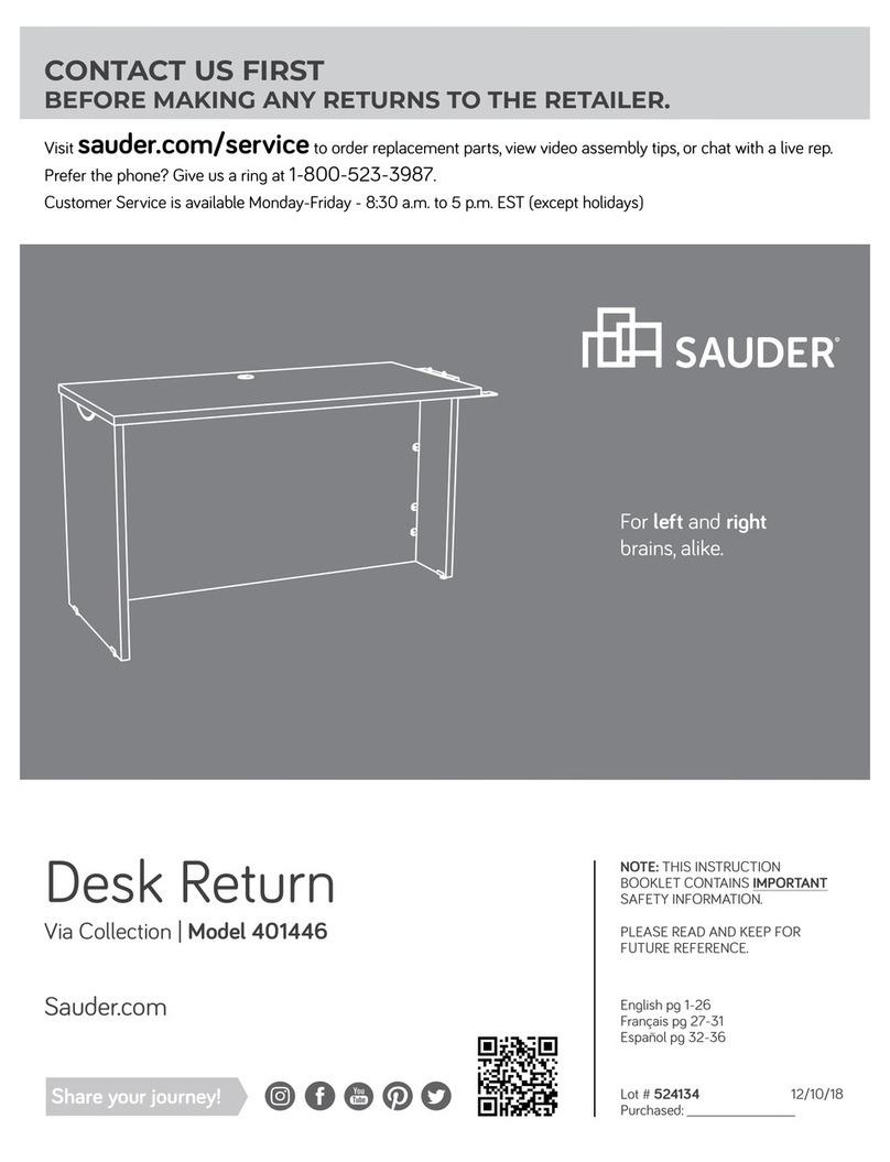
  9. Sauder August Hill 426133 User manual

Sauder August Hill 426133 User manual

sauder.com
NOTE: THIS INSTRUCTION
BOOKLET CONTAINS IMPORTANT
SAFETY INFORMATION.
PLEASE READ AND KEEP FOR
FUTURE REFERENCE.
sauder.com
CONTACT US FIRST
BEFORE MAKING ANY RETURNS TO THE STORE.
Share your journey!
sauder.com
CONTACT US FIRST
BEFORE MAKING ANY RETURNS TO THE RETAILER.
Visit sauder.com/service to order replacement parts, view video assembly tips, or chat with a live rep.
Prefer the phone? Give us a ring at 1-800-523-3987.
Customer Service is available Monday-Friday - 9 a.m. to 5:30 p.m. EST (except holidays)
Sauder.com Enlish p 1-30
Français p 31-35
Español p 36-40
Lot # 539951 01/27/20
Purchased: __________________
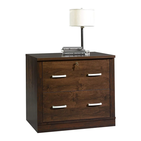
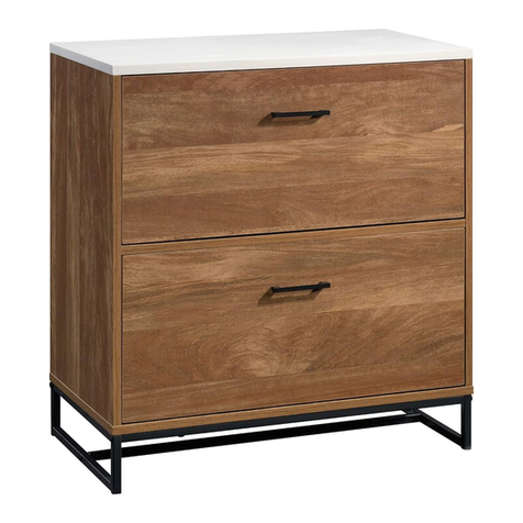
Lateral File
Auust Hill Collection | Model 426133
Congratulations. You
are now an adult.
Table of Contents Assembly Tools Required
Part Identification
Hardware Identification
Assembly Steps
Français
Español
Safety
Warranty
No. 2 Phillips Screwdriver
Tip Shown Actual Size
3
4-5
6-30
31-35
36-40
41-42
43
426133 www.sauder.com/servicePae 2
Part Identification
åWhile not all parts are labeled, some of the parts will have a label or an inked letter on the edge
to help distinguish similar parts from each other. Use this part identification to help identify similar parts.
Now you know
our ABCs.
A RIGHT END (1)
B LEFT END (1)
C TOP (1)
D RIGHT FRONT/LEFT REAR LEG (2)
D61 DRAWER BACK (1)
D87 RIGHT DRAWER SIDE (1)
D88 LEFT DRAWER SIDE (1)
D729 DRAWER BOTTOM (1)
E LEFT FRONT/RIGHT REAR LEG (2)
F FRONT MOLDING (1)
G TOP END MOLDING (2)
H SHELF (1)
J BOTTOM (1)
K UPPER END MOLDING (2)
L LOWER END MOLDING (2)
M END MOLDING (2)
M63 DRAWER BRACE (1)
N BOTTOM MOLDING (1)
O BACK (1)
P BALLAST (2)
Q DRAWER FRONT (1)
A
B
C
D
D
E
E
F
G
G
H
J
K
K
L
L
M
M
N
O
P
P
Q
M63
D61
D87
D88
D729
426133www.sauder.com/service Pae 3
Hardware Identification
FILE ROD - 2
9B
FILE BAR - 2
1B FILE GLIDE - 2
6B
(EXTENSION SET SHOWN SEPARATED)
EXTENSION SLIDE - 2
40MC
EXTENSION RAIL - 2
40MA
APPLIQUE CARD - 5
100P
ANGLE BRACKET - 7
5G
WASHER - 2
10I
10A SLIDE CAM - 2
CAM SCREW - 9
8F
PULL - 2
22K
WOOD DOWEL - 6
15F
FILE BRACKET - 2
12B HIDDEN CAM - 24
1F CAM DOWEL - 15
2F
426133 www.sauder.com/servicePae 4
Hardware Identification
åScrews are shown actual size. You may receive extra hardware with your unit.
BLACK 9/16" LARGE HEAD SCREW - 14
1S
BROWN 7/16" LARGE HEAD SCREW - 4
6S
SILVER 1/4" MACHINE SCREW - 2
61S
100S BLACK 2-3/4" FLAT HEAD SCREW - 4
BLACK 9/16" FLAT HEAD SCREW - 12
32S
BLACK 1-15/16" FLAT HEAD SCREW - 3
113S
30S BLACK 1-9/16" FLAT HEAD SCREW - 5
3S GOLD 5/16" FLAT HEAD SCREW - 8
426133www.sauder.com/service Pae 5
Step 1 Look for this icon. It means a
video assembly tip is available at
www.sauder.com/service/tips
å Assemble your unit on a carpeted floor or on the empty carton to avoid scratchin your unit or the floor.
å Turn six BLACK 9/16" FLAT HEAD SCREWS (32S) into the LEFT END (B) until the shoulders of the SCREWS rest on the
surface of the LEFT END.
å NOTE: Do not overtihten the SCREWS.
å Slide the UPPER END MOLDING (K) onto the LEFT END (B). Line up the roove in the MOLDING over the heads of the
SCREWS in the LEFT END.
å NOTE: If the MOLDING comes up o of the SCREWS, remove it and slide it on aain.
å Slide the END MOLDING (M) onto the LEFT END (B) until it is aainst the UPPER END MOLDING (K). Line up the roove in
the MOLDING over the heads of the SCREWS in the LEFT END.
å NOTE: If the MOLDING comes up o of the SCREWS, remove it and slide it on aain.
These edes
should be even.
B
K
M
BLACK 9/16" FLAT HEAD SCREW
(6 used in this step)
32S
Shoulder
Apply pressure with your hands
as you uide the MOLDINGS over
the SCREWS and onto the ENDS.
Apply pressure with your hands
as you uide the MOLDINGS over
the SCREWS and onto the ENDS.
Shoulder
426133 www.sauder.com/servicePae 6
Step
å Slide the LOWER END MOLDING (L) onto the LEFT END (B).
Line up the roove in the MOLDING over the heads of the
SCREWS in the LEFT END.
å NOTE: The MOLDING should be even on both edes of the END.
å NOTE: If the MOLDING comes up o of the SCREWS, remove it
and slide it on aain.
Step 2
BL
Shoulder
Apply pressure with your hands
as you uide the MOLDINGS over
the SCREWS and onto the ENDS.
426133www.sauder.com/service Pae 7
Just think. The sooner
you do this, the sooner
you do somethin else.
Hardware Usage Guide
Start Tighten
Arrow
Minimum
190 degrees
Caution
Risk of damage or
injury. HIDDEN CAMS
must be completely
tightened. HIDDEN
CAMS that are not
completely tightened
may loosen, and parts
may separate. To
completely tighten:
Arrow
Maximum
210 degrees
3. Start Tighten
Arrow
Minimum
190 degrees
Caution
Risk of damage or
injury. HIDDEN CAMS
must be completely
tightened. HIDDEN
CAMS that are not
completely tightened
may loosen, and parts
may separate. To
completely tighten:
Arrow
Maximum
210 degrees
HOW TO USE A HIDDEN CAM & CAM DOWEL
Hole
Hidden Cam
Cam Dowel
2.
Hole
Hidden Cam
Cam Dowel
Insert the metal end of the CAM
DOWEL into the HIDDEN CAM.
Metal end
Arrow
1. Push a HIDDEN CAM into
the part. The arrow in the
HIDDEN CAM must point
toward the hole in the
edge of the board.
Cam Screw
Hidden Cam
Arrow
Push a HIDDEN CAM into
the part. The arrow in the
HIDDEN CAM must point
toward the hole in the
ede of the board.
Hole
2. 3.
1
2
Insert the CAM SCREW into the HIDDEN CAM.
Tihten the HIDDEN CAM.
HOW TO USE A HIDDEN CAM & CAM SCREW
Turn the CAM SCREW until
the shoulder is aainst the
surface of the part.
1.
426133 www.sauder.com/servicePae 8
å Turn four CAM SCREWS (8F) into one set of the LEGS (D and E) as
shown in diaram 1
å Insert two WOOD DOWELS (15F) into the LEGS (D and E) as shown
in diaram 1.
å Flip over the LEGS (D and E) as shown.
å Push two HIDDEN CAMS (1F) into the LEGS (D and E) as shown
in diaram 2. Then, insert the metal end of a CAM DOWEL (2F) into
each HIDDEN CAM.
Step 3
D
D
E
E
F
L
I
P
O
V
E
R
F
L
I
P
O
V
E
R
8F
8F
15F
15F
Do not tihten the HIDDEN CAMS in this step.
Arrow
1F
2F
(2 used)
Metal end
1
2
1
2
426133www.sauder.com/service Pae 9
å Push four HIDDEN CAMS (1F) into the LEFT END (B).
å Fasten the LEGS (D and E) to the LEFT END (B). Tihten
four HIDDEN CAMS.
å NOTE: Be sure the WOOD DOWELS in the LEGS insert
into the RIGHT END.
Step 4
B
B
E
D
1F
Arrow
1F
Arrow
Anled ede
Anled ede
426133 www.sauder.com/servicePae 10
å Separate the EXTENSION SLIDES (40MC) from the EXTENSION RAILS (40MA) as shown in the upper diaram below. Be
prepared, the parts are reasy.
å Fasten a EXTENSION RAIL (40MA) to the LEFT END (B). Use two GOLD 5/16" FLAT HEAD SCREWS (3S)
throuh holes #1 and #4.
å NOTE: For each EXTENSION RAIL, turn a SCREW into the hole shown in the enlared diaram. Then, slide the inner
cartride of the EXTENSION RAIL in to find the other hole that lines up with the hole in the LEFT END. Turn a SCREW into
this hole.
å NOTE: The EXTENSION SLIDES will be used later for the DRAWERS.
å Insert a WOOD DOWEL (15F) into the LEFT END (B).
Step 5
Push the black lever in and pull the SLIDE from the RAIL.
40MA40MC
Open end
GOLD 5/16" FLAT HEAD SCREW
(2 used for the RAILS)
3S
3
2
1
4
B
15F
E
D
426133www.sauder.com/service Pae 11
å Push four HIDDEN CAMS (1F) into the SHELF (H). Then, insert the metal end of a CAM DOWEL (2F)
into each HIDDEN CAM.
å Fasten the SHELF (H) to the LEFT END (B) and LEG (E). Tihten two HIDDEN CAMS.
Step 6
H
H
D
B
Surface with
HIDDEN CAMS
These holes must be here. Arrow
1F
2F
(4 used)
Metal end
Arrow
1F
2F
Metal end
426133 www.sauder.com/servicePae 12
å Push three HIDDEN CAMS (1F) into the BACK (O). Then,
insert the metal end of a CAM DOWEL (2F) into each
HIDDEN CAM.
å Fasten the BACK (O) to the SHELF (H). Tihten three
HIDDEN CAMS.
Step 7
O
O
H
Surface with
HIDDEN CAMS
1F
2F
(3 used)
Metal end
Arrow
426133www.sauder.com/service Pae 13
å Push four HIDDEN CAMS (1F) into the BOTTOM (J). Then,
insert the metal end of a CAM DOWEL (2F) into each
HIDDEN CAM.
å Slide a BOTTOM MOLDING* (N) onto the notched ede
of the BOTTOM (J).
å *U.S. Patent No. 5,499,886
Step 8
Slide the BOTTOM MOLDING (N)
onto the notched ede.
N
J
Notched ede
Do not tihten the HIDDEN CAMS in this step.
The roove
is closer to
this ede.
Arrow
1F
2F
Metal end
Arrow
1F
2F
(4 used)
Metal end
426133 www.sauder.com/servicePae 14
å Fasten the BOTTOM (J) to the LEFT END (B). Tihten two
HIDDEN CAMS.
å NOTE: Be sure the WOOD DOWEL in the LEFT END
insert into the BOTTOM.
å Fasten the BOTTOM (J) to the BACK (O). Use three
BLACK 1-15/16" FLAT HEAD SCREWS (113S).
Step 9
J
B
426133www.sauder.com/service Pae 15
O
BLACK 1-15/16" FLAT HEAD SCREW
(3 used in this step)
113S
å Turn six BLACK 9/16" FLAT HEAD SCREWS (32S) into the RIGHT END (A) until the shoulders of the SCREWS rest on the
surface of the RIGHT END.
å NOTE: Do not overtihten the SCREWS.
å Slide the UPPER END MOLDING (K) onto the RIGHT END (A). Line up the rooves in the MOLDINGS over the heads of the
SCREWS in the RIGHT END .
å NOTE: If the MOLDING comes up o of the SCREWS, remove it and slide it on aain.
å Slide the END MOLDING (M) onto the RIGHT END (A) until it is aainst the UPPER END MOLDING (K). Line up the
rooves in the MOLDINGS over the heads of the SCREWS in the RIGHT END.
å NOTE: If the MOLDING comes up o of the SCREWS, remove it and slide it on aain.
Step 10
A
K
M
BLACK 9/16" FLAT HEAD SCREW
(6 used in this step)
32S
Shoulder
Apply pressure with your hands
as you uide the MOLDINGS over
the SCREWS and onto the ENDS.
Apply pressure with your hands
as you uide the MOLDINGS over
the SCREWS and onto the ENDS.
These edes
should be even.
Shoulder
426133 www.sauder.com/servicePae 16
å Slide the LOWER END MOLDING (L) onto the
RIGHT END (A). Line up the roove in the MOLDING over
the heads of the SCREWS in the RIGHT END.
å NOTE: The MOLDING should be even on both edes of
the END.
å NOTE: If the MOLDING comes up o of the SCREWS,
remove it and slide it on aain.
Step 11
Shoulder
Apply pressure with your hands
as you uide the MOLDING over
the SCREWS and onto the ENDS.
L
A
426133www.sauder.com/service Pae 17
Step 12
å Turn four CAM SCREWS (8F) into the remainin set of
the LEGS (D and E) as shown in diaram 1
å Insert two WOOD DOWELS (15F) into the LEGS (D and E) as shown
in diaram 1.
å Flip over the LEGS (D and E) as shown.
å Push two HIDDEN CAMS (1F) into the LEGS (D and E) as shown
in diaram 2. Then, insert the metal end of a CAM DOWEL (2F) into
each HIDDEN CAM.
D
D
E
E
F
L
I
P
O
V
E
R
F
L
I
P
O
V
E
R
8F
8F
15F
15F
Do not tihten the HIDDEN CAMS in this step.
Arrow
1F
2F
(2 used)
Metal end
1
2
1
2
426133 www.sauder.com/servicePae 18
å Push four HIDDEN CAMS (1F) into the RIGHT END (A).
å Fasten the LEGS (D and E) to the RIGHT END (A). Tihten
four HIDDEN CAMS.
å NOTE: Be sure the WOOD DOWELS in the LEGS insert
into the RIGHT END.
Step 13
A
A
D
E
1F
Arrow
1F
Arrow
Anled ede
Anled ede
426133www.sauder.com/service Pae 19
å Fasten a EXTENSION RAIL (40MA) to the RIGHT END (A). Use two GOLD
5/16" FLAT HEAD SCREWS (3S) throuh holes #1 and #4.
å NOTE: For each EXTENSION RAIL, turn a SCREW into the hole shown in the
enlared diaram. Then, slide the inner cartride of the EXTENSION RAIL
in to find the other hole that lines up with the hole in the RIGHT END. Turn a
SCREW into this hole.
å Insert a WOOD DOWEL (15F) into the RIGHT END (A).
Step 14
A
Open end
GOLD 5/16" FLAT HEAD SCREW
(2 used for the RAILS)
3S
1
2
3
4
15F
426133 www.sauder.com/servicePae 20

Other Sauder Indoor Furnishing manuals
Sauder 409937 User manual

Sauder

Sauder 409937 User manual

Sauder 424273 User manual

Sauder

Sauder 424273 User manual

Sauder 415421 User manual

Sauder

Sauder 415421 User manual

Sauder Cannery Bridge 424198 User manual

Sauder

Sauder Cannery Bridge 424198 User manual

Sauder Palladia 413998 User manual

Sauder

Sauder Palladia 413998 User manual

Sauder Soft Modern 415138 User manual

Sauder

Sauder Soft Modern 415138 User manual

Sauder Anywhere Dakota Pass 418231 User manual

Sauder

Sauder Anywhere Dakota Pass 418231 User manual

Sauder 426930 User manual

Sauder

Sauder 426930 User manual

Sauder 415137 User manual

Sauder

Sauder 415137 User manual

Sauder Hammond 431249 User manual

Sauder

Sauder Hammond 431249 User manual

Sauder Soft Modern 415007 User manual

Sauder

Sauder Soft Modern 415007 User manual

Sauder 412885 User manual

Sauder

Sauder 412885 User manual

Sauder County 418529 User manual

Sauder

Sauder County 418529 User manual

Sauder Harvey Park 427118 User manual

Sauder

Sauder Harvey Park 427118 User manual

Sauder Briarbrook 430077 User manual

Sauder

Sauder Briarbrook 430077 User manual

Sauder Heritage Hill 109843 User manual

Sauder

Sauder Heritage Hill 109843 User manual

Sauder Costa Credenza 419959 User manual

Sauder

Sauder Costa Credenza 419959 User manual

Sauder Costa 428724 User manual

Sauder

Sauder Costa 428724 User manual

Sauder DESIGNER'S IMAGE 430616 User manual

Sauder

Sauder DESIGNER'S IMAGE 430616 User manual

Sauder 430628 User manual

Sauder

Sauder 430628 User manual

Sauder 412740 User manual

Sauder

Sauder 412740 User manual

Sauder 423408 User manual

Sauder

Sauder 423408 User manual

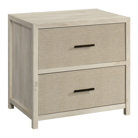
Sauder Lateral File User manual

Sauder

Sauder Lateral File User manual

Sauder Barrister Lane 422268 User manual

Sauder

Sauder Barrister Lane 422268 User manual

Popular Indoor Furnishing manuals by other brands

Techni Mobili RTA-7002 Assembly instructions

Techni Mobili

Techni Mobili RTA-7002 Assembly instructions

modway EEI-3890 manual

modway

modway EEI-3890 manual

Placa & Ponto P1009-BRA Assembly instruction

Placa & Ponto

Placa & Ponto P1009-BRA Assembly instruction

Courtyard Creations KTS136P-WM Assembly instructions

Courtyard Creations

Courtyard Creations KTS136P-WM Assembly instructions

Sitting Vision Relax4U manual

Sitting Vision

Sitting Vision Relax4U manual

OfficeSource PLTCRKB36WF24 Assembly instructions

OfficeSource

OfficeSource PLTCRKB36WF24 Assembly instructions

deante ADR 0821 quick start guide

deante

deante ADR 0821 quick start guide

Costway JV11365 manual

Costway

Costway JV11365 manual

Ameriwood HOME COFFEE BAR 9981015COM Assembly instruction

Ameriwood HOME

Ameriwood HOME COFFEE BAR 9981015COM Assembly instruction

BOBOCHIC RIVOLI Assembly instructions

BOBOCHIC

BOBOCHIC RIVOLI Assembly instructions

calligaris ACE quick guide

calligaris

calligaris ACE quick guide

Sorelle Vista 5 Drawer Chest Assembly instruction

Sorelle

Sorelle Vista 5 Drawer Chest Assembly instruction

Notável Móveis NT 1295 Assembly instructions

Notável Móveis

Notável Móveis NT 1295 Assembly instructions

Exclusive Heritage MG-10048S installation guide

Exclusive Heritage

Exclusive Heritage MG-10048S installation guide

Royal Catering RCWR-80.2 user manual

Royal Catering

Royal Catering RCWR-80.2 user manual

Schardt Wiko 3 Schube 05 494 Assembly instructions

Schardt

Schardt Wiko 3 Schube 05 494 Assembly instructions

Furniture Solutions AKIRA 18AKIT10 instruction manual

Furniture Solutions

Furniture Solutions AKIRA 18AKIT10 instruction manual

Displays2go LITTER GRAPHIC Assembly instructions

Displays2go

Displays2go LITTER GRAPHIC Assembly instructions

manuals.online logo
manuals.online logoBrands
  • About & Mission
  • Contact us
  • Privacy Policy
  • Terms and Conditions

Copyright 2025 Manuals.Online. All Rights Reserved.